This article was originally posted on PinballRehab.com.
Reproduced with permission from terryb.
Written by terry
This is part four of a seven part series intended to provide a basic knowledge of electronics, test equipment, pinball manuals and troubleshooting in order to allow the reader to effectively repair pinball games. With that goal in mind I have simplified the explanations and purposely glossed over some details that add no value, and can easily confuse beginners.
Digital Multimeter
A. Basic Electronics
B. Transistors
C. Integrated Circuits
D. Test Equipment
E. Operators Manual
F. Reading Schematics
G. Electronics Troublshooting
The most common piece of test equipment you will use while troubleshooting a pinball game is a digital multimeter (DMM). You can use it to test voltage, resistance, current and on some models temperature, capacitance and frequency.
My recommended meter is the Fluke 87, and you can get one used on eBay for under $150. [Editor’s note: Since this was published, prices have risen on eBay for a Fluke a bit. And there are some differences between the Fluke 87 models.]
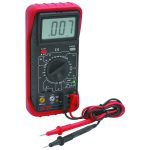
If you’re not looking to spend that kind of money the Cen-Tech model P37772 [Ed: Often referred to as the ’11 Function Digital Multimeter] does most of what you need (with a few caveats) for a lot less. You can find the product at Harbor Freight for $25 and I’ve seen it on sale for $19.
There are three issues you should be aware of on the cheaper DMM’s. They do not have the fusing and safety features that a quality DMM does. This is not a major issue unless working on high voltage or AC circuits. Low cost DMM’s are also not as accurate in their readings, but are generally acceptable for pinball troubleshooting.
Cheap DMM’s will typically not refresh fast enough to catch fast spikes in a supply voltage. For example, when troubleshooting a reset problem. Also, when using the DMM in AC mode to test ripple on a supply voltage some will give erroneous, or inaccurate readings. It requires a TrueRMS meter to do this accurately.
[Editor’s note: For our take on this topic, check out recommended voltmeters.]
Do not buy one of those crappy $9 DMM’s you see on sale everywhere.
I’m sure the Cen-Tech will not last as long as my trusty Fluke, but you can afford to buy yourself a couple at that price. Although I will specifically speak about the Cen-Tech DMM (PDF manual) in this article, any DMM will have the same functions and general usage.
The primary interface on any DMM is the function/range selector. On the Cen-Tech it is a large rotary dial used to select the function (voltage, current, resistance, etc.) and the range (we’ll talk more about this later). There are also four input jacks for connecting the red and black test leads (COM, V/Ω/Hz, 200Ma fused and 20A un-fused. The red test lead is also called positive and the black test lead is also called negative.
By the way, Ω equals ohms.
Additionally the Cen-Tech has functions for checking frequency, capacitance, temperature and transistors.
Testing Resistance
Resistance should always be tested with the game’s power off. Put the red lead in V/Ω/Hz and the black lead in COM. Turn the function/range dial to resistance (the Ω symbol) and then your selected range: 200, 2K, 20K, 200K, 2M and 20M. In each case only the higher end of the range is printed on the DMM, so 200K really means 20K to 200K.
If you know roughly what resistance to expect set the range to the next higher choice (i.e. – if you’re testing a 1K resistor set the dial to 2K). If not just start at the bottom and work your way up. You will get an out of range or null indicator (which on the Cen-Tech is the number one and a dot) if the item under test is open or you need to go to a higher range.
When checking resistance the polarity of the leads doesn’t matter. In other words, you can put either lead on either side of the resistor. Always be careful when testing resistance in circuit because other parallel circuity can give you false readings (see testing resistors).
Continuity and Diode Mode
The final ohm range is diode/continuity (marked with a diode and audio symbol). In this mode we are technically measuring voltage rather than ohms. The DMM places a small voltage on the positive lead and then measures the voltage drop at the negative lead.
Continuity is the theoretical lack of resistance. Even a four foot length of wire has some resistance,but what we are concerned with when testing continuity is identifying a break in the circuit (the wire is broken in the middle or a connector has a bad connection).
You will commonly use this setting when testing for shorts to ground or testing continuity on a fuse, wire, board trace or connector. Polarity does not matter when testing continuity. Unlike resistance it is a binary (the circuit is either open or closed) measurement. In continuity mode you will get a beep if there is continuity between two test points.
This same setting is used for testing diodes, bridge rectifiers and transistors (see testing diodes, testing bridge rectifiers or testing transistors for more info). When testing components with this mode you will get a reading indicating the drop in voltage rather than a beep. Polarity of the probes does matter when testing diodes, rectifiers and transistors.
Testing Voltage
To test voltage put the red lead in V/Ω/Hz and the black lead in COM and turn the function/range dial to either AC or DC (AC is marked with a V and a squiggly line and DC is marked with a V and a horizontal line with three dashes under it) and the specific voltage range (see this article for more info on AC and DC). Just as with resistance, each setting is a range, so 20 volts means between 2 (the next lower setting) and 20.
If you are unsure what voltage is present always start with the highest setting and move down as appropriate for a more accurate reading. The meter will indicate an over-range condition if the reading is higher than the range setting with the number one and a dot. Although this should not damage your DMM, it’s still a good idea to start with the highest range and work down.
When testing DC polarity matters, so you always place the black lead on ground and the red lead on the voltage you are testing. When testing AC polarity does not matter and you place your test leads across the component you are testing (transformer, bridge rectifier, AC lighting, etc.). For example, when testing a DC bulb, the black lead goes on ground and the red lead goes on either leg of the bulb (you actually want to check both in case the bulb is burnt out). When testing an AC bulb you put a test lead on each leg of the bulb.
Other Tests
The transistor tester is generally useless since the transistor has to be out-of-circuit and it won’t test Darlington transistors. On the other hand, the capacitor tester can sometimes come in handy although it is not as accurate as an ESR meter (which costs over $100 and generally isn’t worth the investment). While this may sound odd, the smaller the cap the more likely you will get an accurate assessment.
On the CenTech DMM the capacitor must be removed from the circuit in order to plug it into a socket on the meter. With my Fluke I can test caps with the test probes and therefore only have to remove one lead. So other options are available, but honestly you will seldom have to test a capacitor other than for a short.
If you do need to test a capacitor turn the selector to F and then select the range the capacitor under test should fall within. A good capacitor can read 10 – 20% more than it’s rated value, but should never read below that number.
Although you can test current and frequency with the meter you will probably never need to so I won’t cover it here.
One last quick mentions goes to the temperature probe. This is actually kind of handy for setting your variable heat gun to a specific temperature when working with playfield plastics or ramps.
Logic Probe
While I am presenting the logic probe second, in my opinion it is as invaluable as a DMM. The purpose of a logic probe is to test logic circuits where the reading can be low, high or pulsed (alternating between low and high). A DMM cannot read pulsed circuits and there are a lot of pulsed circuits in the backbox.
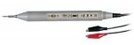
MCM Electronics sells the Tenma 72-500 logic probe (see Image 2) for $35 and has a Tenma 72-190 for under $25. Both will do the job, although the 72-500 can also pulse circuits. Fry’s Electronics also has several choices in the $15 – $30 range. Elenco also has a good product.
Some logic probes will vary from the information provided here, so always read the manual for your model. All logic probes will have a probe used to test circuits and LED’s that indicate the circuit status, some will have a TTL/CMOS switch or a PPS (pulses per second) switch and most will have black and red leads with alligator clips. Some logic probes are self-contained (battery powered) and will not have the red and black leads.
If your logic probe has alligator clips, attach the black clip to ground and the red clip to the logic supply voltage (between 5 volts and 12 volts). TTL logic circuits are always 5 volts and CMOS logic circuits can be either 5 volts or 12 volts.
Most circuits in a pinball game are either 5 volt TTL or 12 volt CMOS (the switch matrix, for example). The one exception is the LM339 voltage comparator (used in switch optics circuits) which is 5 volt CMOS. See this article for more info on TTL and CMOS.
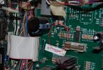
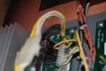
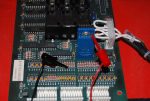
Most boards have a small loop of wire or small post that is labeled with ground or the supply voltage (see Image 3 and Image 4).
Set the TTL/CMOS switch to the appropriate setting based on the circuit you are troubleshooting. If you’re on a 5 volt circuit set it to TTL and if you’re on a 12 volt circuit set it to CMOS. For logic probes that don’t have a TTL/CMOS switch they will automatically select the correct logic family setting based on the supply voltage.
Some logic probes have a PPS switch (usually .5PPS and 400PPS) which is only used when you are using your logic probe to pulse a circuit rather than testing it.
Now on to the fun stuff. Place your probe on the component under test and you should see some LED action. In the case of the Tenma 72-500 a red LED will light for a logic 1 (high) and a green LED will light for a logic 0 (low). If the signal is pulsed the red and green LED’s will alternate. Note that some logic probes use a yellow LED to indicate a pulsed circuit.
For a more detailed explanation on logic probes, see this page on using Digital Logic Probes.
Other Equipment
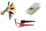
Your testing experience will go much better with the addition of a couple of other pieces of test equipment (see Image 5). While some are for convenience others help ensure you don’t short your test probe across two leads, which is easy to do on a small transistor or IC. While this typically won’t cause any permanent problems (other than making you jump when a solenoid suddenly fires) it’s still best to avoid.
The first is some 2 – 3′ alligator test clips, which will help extend the reach of your test probes. For example, testing continuity from the backbox to the playfield. You can also buy them with a plug on one end that will fit in the COM connection on your multimeter and can then be clipped to ground.
Our next item is the mini-grabber (also called mini-clip) test clip, which have a small J shaped, spring-loaded clip. These are great for clipping onto a ground or Vcc test point or the lead of a component (transistor, resistor, etc.).
When working with .1″ male connectors (switch and lamp matrix, etc.) I find .1″ female to female jumpers come in extremely handy. You can get them at Fry’s Electronics in a variety of lengths, but 6″ works well.
You can also purchase add-on test clips that slide over the end of your DMM test probe. Both alligator clips and mini-grabbers are available and extremely helpful. I actually use both the add-on test clips and the standalone test clips since each will work better in different situations.
The last item is a selection of IC test clips (DIP clips). The clips are placed over the IC and provide extended test points where you can use a mini-grabber or your test probe to read voltages. To cover all the bases you will need a 14, 16, 18 and 20 pin IC test clip.
You could also just use a 14 pin test clip which will fit on larger IC’s, but not all pins will be available for testing at one time. On the other hand you could go with a 20 pin test clip and let it overhang the chip, but the wider clip will sometimes not physically fit on a smaller pin IC because of surrounding components getting in the way.
Ed at Great Plains Electronics sells the 3M line of DIP clips at a very reasonable price. The multimeter test probe add-on clips should be available wherever you purchased your DMM. All of the other items can be found at your local electronics store or online.
Comments
Comments, including general questions about electronics troubleshooting, suggestions, improvements, errors, etc. are welcome (see below).
If you have a specific question about your game, please see our FAQ section.