What is a Stepper Unit?
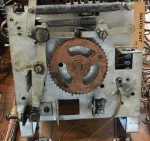
A stepper unit is a wheel that turns, one step at a time. It may keep track of which player is up, ball in play, coin inserted, etc. Below are examples of stepper motors used in EM pinball machines.
Types of stepper motors include:
- Step up / step down
- Step up / reset
- Continuous
- Credit Free game wheel – a special case (see below).
All of those stepper motors work on similar principals so working on any of them is similar. Continuous steppers may have only one solenoid. Those that change directions should have two solenoids.
Additionally, some steppers might have a full moving disk, while others have copper arms, called wipers. Those with wipers do not need to be removed. A full disk will have to be removed (note warning about positioning and marking the disk, below).
It Does Not Turn Well – Replace or Tighten the Springs!
No, don’t do it.
So many people try to fix problems of slow or poorly moving steppers by playing with the springs. Old springs, even those looking corroded, are rarely the issue. It is OK to replace them. But we rarely tighten them. A poorly operating stepper is usually a sign that it needs to be cleaned up. In most cases, a careful cleaning and it will snap into position like it is new.
Materials and Tools Needed
The materials and tools recommended are the same as those used to work on Score Reels.
Disassembly
 For all disassemblies, you will need an organized place to store the parts. We use old muffin tins.
The stepper motor assembly us usually attached with wood screws. Remove the wood screws to be able to access the stepper motor. Sometimes there maybe other nearby assemblies that should be removed, such as score reels, in order to easily work.
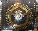
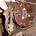
Score Contact Side

Note: If the next step involves removing a disk or wipers, and you have a step up / step down, or step up / reset (2 solenoids) be sure to carefully mark the position of the disk. It is best to reset the stepper back to the home or zero position, then mark its location so it can be put back exactly in the same position, touching the same contacts.
The next step depends on which type of assembly you have. If you have the type with a full spinning disk on top, it will be necessary to remove that disk. Some are held in place by three screws. Others may have a single large nut holding it in place.
Reset the stepper, mark its position, then remove the disk. Those with the three screws should be relatively easy to remove. Those with the single bolt might require holding the shaft on the other side to loosen the nut.
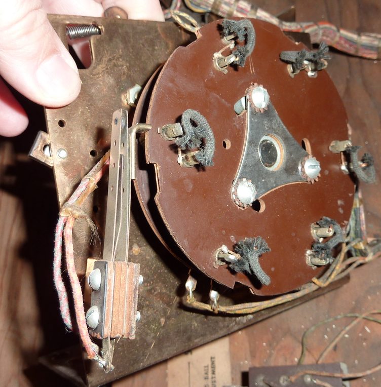
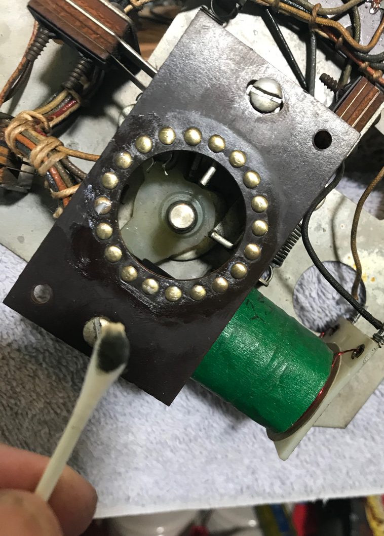
If the stepper is the type with several ‘wipers’, it is not necessary to remove them and we suggest that you not try.

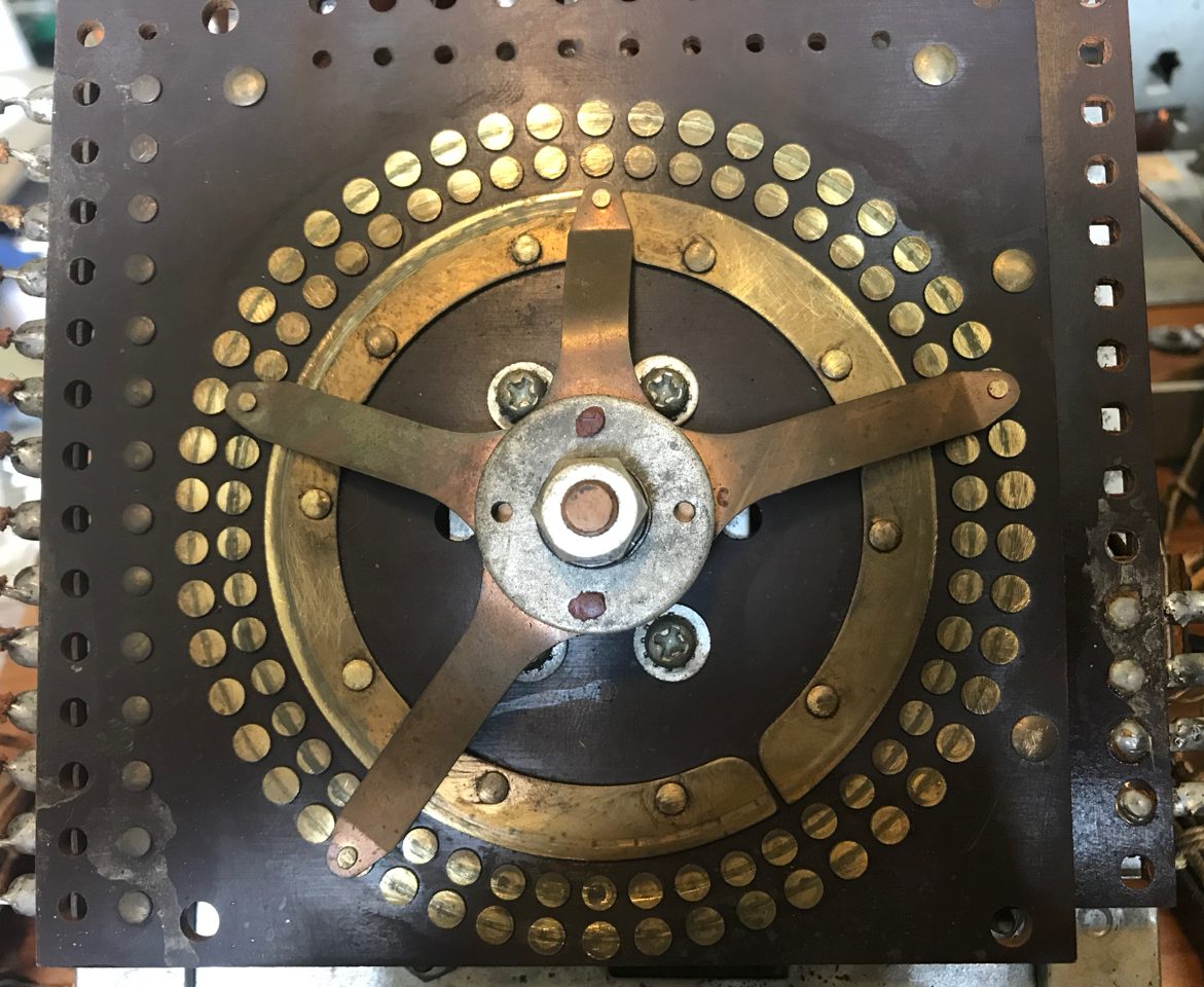
Once the stationary contacts have been exposed, it is time to clean them. Wipe on a thin layer of Mothers Mag and Aluminum Polish. Buff the contacts either with a microfiber cloth (an old t-shirt also works) or the buffing wheel of a Dremel (wear safety glasses!). Don’t overdo it as the buffing does remove a layer of the contact. Wipe off the leftover polish with a rag. Clean the contacts with isopropyl alcohol (not rubbing alcohol).

For those with wipers, soak a Q-tip with isopropyl alcohol and gently lift each tip and clean it. Go back a second time with a new tip.
For those with a full disk, clean the bottom contacts. These are usually thin and spring loaded. Usually a Q-tip with isopropyl alcohol works just fine.
There needs to be a very thin layer of lubricant on the contact surface to cut down on wear. We use Finish Line Dry Bicycle Chain Lubricant. Put a few drops on a Q-tip, then wipe the surface. A shine should appear. This lubricant must be thin or resistance to the electrical current will develop. A very thin layer of Teflon grease or Super Lub can also be used, but it must be very thin. The photo of the lube is from a score reel board, but the concept is the same.
Leave this side disassembled for now.
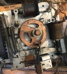
Gear / Solenoid Side

On the other side of the stepper are the gears and solenoid(s) that move the wheel. This is the side that gets gummed up with old grease and dirt.
Note about lubricants: Only metal to metal parts should be lubricated. Any time there is a plastic / nylon part there should not be any lubricant. Also never lubricate the plunger nor any parts that go into the coil. Old grease must be removed, usually by wiping, then a alcohol wash. We use Teflon grease, Super Lube, or sewing machine oil but only in small amounts.

If this is a step up / step down (or reset) stepper, reset the wheel to home (zero) prior to removing the center spring. This is done by pressing the plunger of one of the two solenoids. Reset steppers should ‘snap’ back to zero. ‘Step down’ steppers will have to have the solenoid pressed repeatedly until the stepper is set to zero or home.
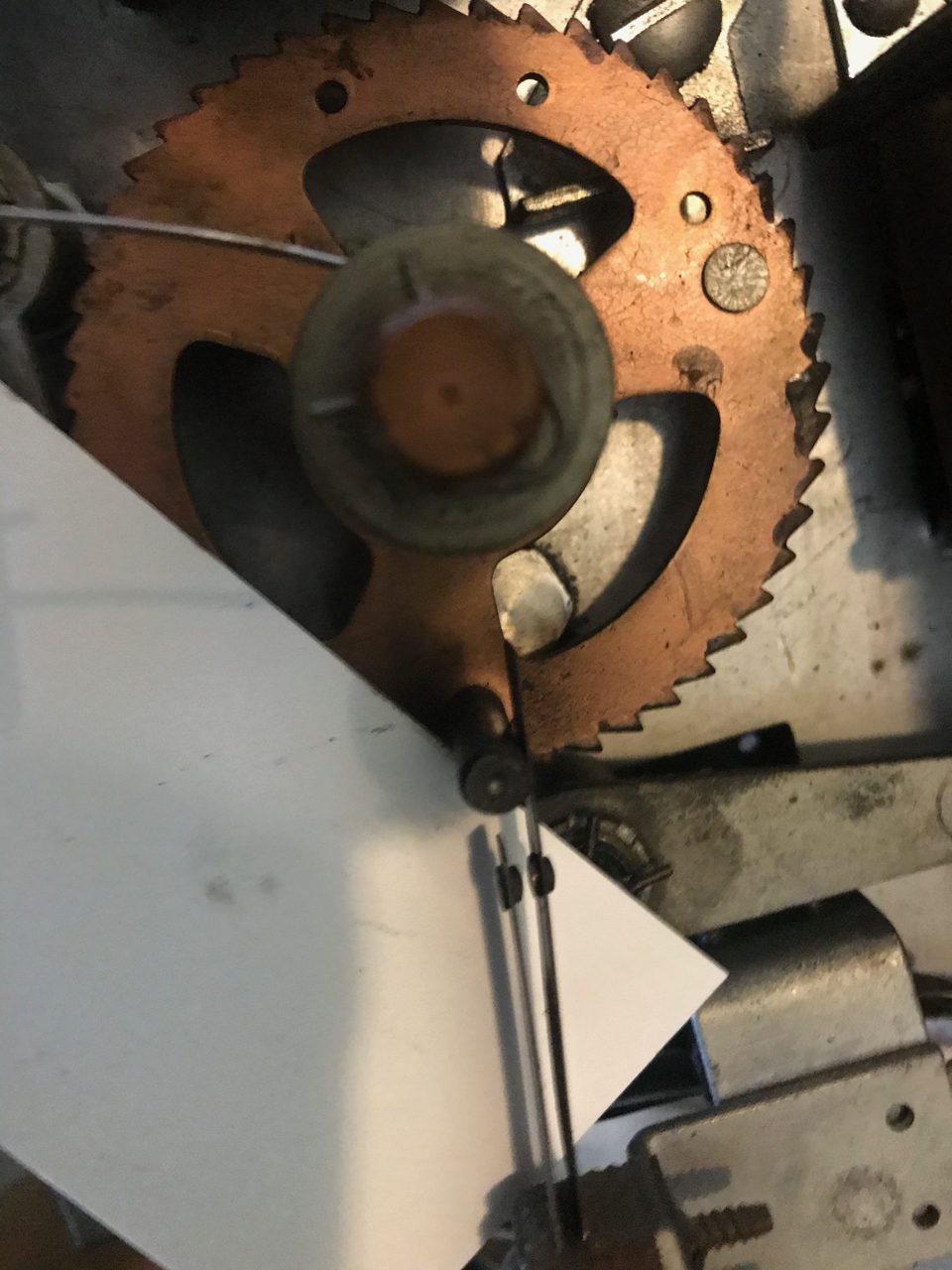
Carefully turn over the stepper, being careful to not damage the board or the wiper blades. Identify and inspect the parts. If there is a spring to the center shaft, carefully lift it off the post, then hold it and slowly unwind, counting the turns. In our case, it turned 3.5 times. That means we turned it past the post 4 times to return it to the original tension.
 Other springs may need to be removed to clean or disassemble the stepper. Just take pictures, note the different sizes, carefully remove them and set them aside.
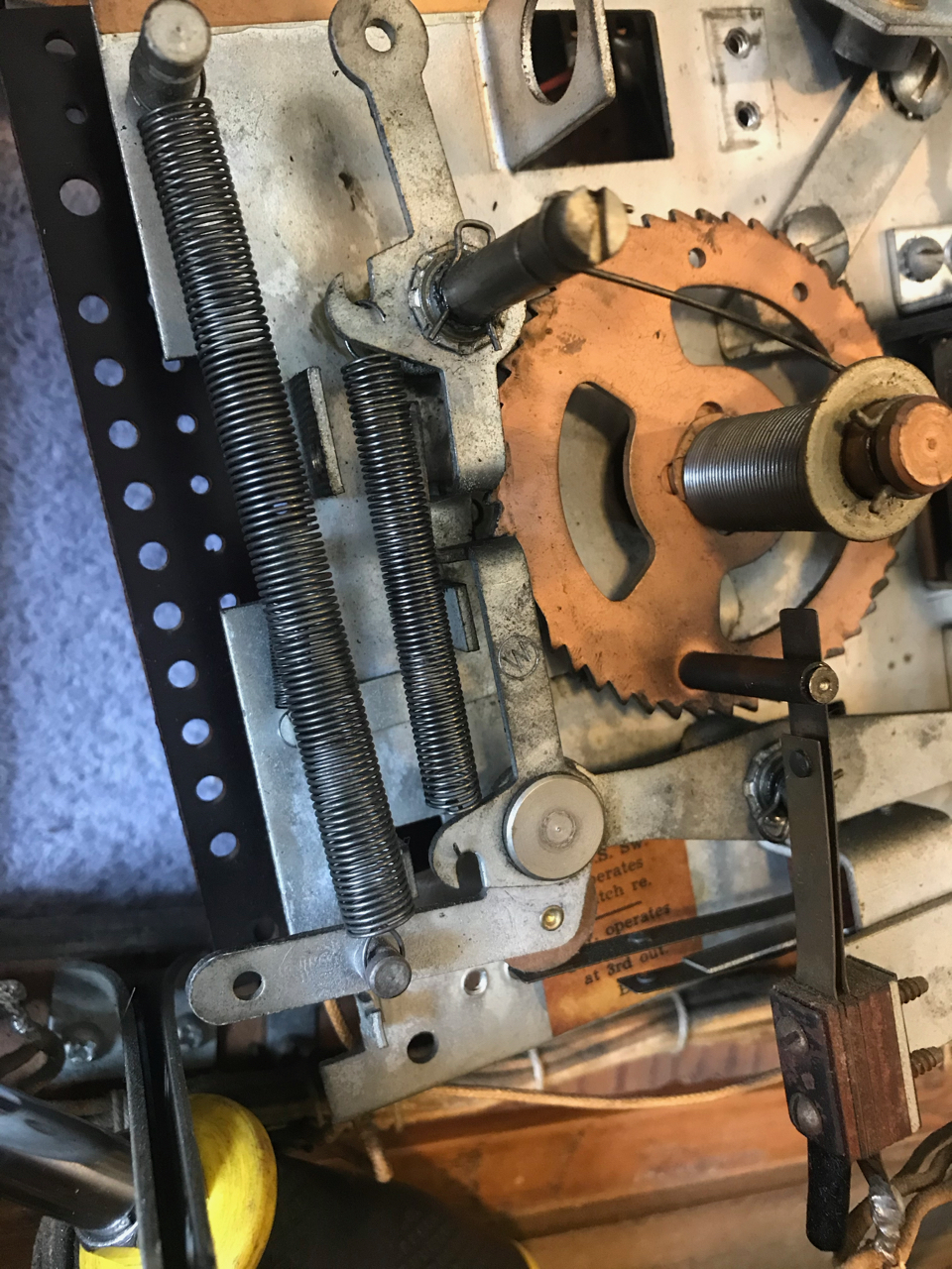
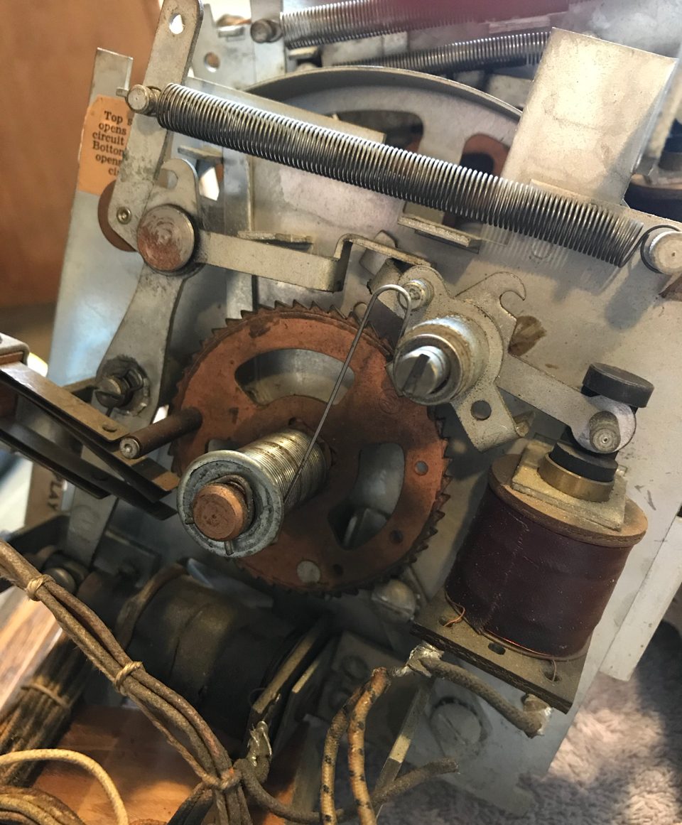
On the stepper in these photos, there are two levers or linkage arms – each attached to a solenoid. Those are the ones connected to the springs. They are likely encrusted in dirt and solidified grease and should be removed. Usually they are held in place by a retaining ring. Take pictures! Study the way the two levers work together. They will have to be reassembled exactly the same way. Carefully remove the retaining rings and store it in the parts container.
 Simply pull off each of the lever / linkage arms. These will need to be cleaned. We use isopropyl alcohol and a rag. Also take a fine rag, like a section of an old T-shirt, dampen with alcohol, and fish it through the center. Do this so that it is clean.
Then wipe everything off of the posts where these levers / linkages were positioned. Set the part aside.
 Prior to removing the coil stop, check the other side to see if the coil stop is held in place by two machine screw nuts. If so, remove them.
 Remove the two screws holding the coil stop in place. This will allow you to remove the coil and let it hang aside. If there is more than one coil, remove them both in the same manner.
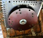
At this point, the only remaining item on the bracket is the large gear wheel in the center. Generally, it is not necessary to remove this. However, insure that it spins freely. If it does not, try washing the area behind the gear with alcohol, wipe that off and let it dry. This should free it up to spin freely.
Remove any remaining grease and gunk off the large gear.
Clean out the coil sleeve of the coils, as well as the plunger(s) and remaining levers with a rag and isopropyl alcohol. Clean the coil stop(s).
Lubrication
 Any time there is metal to metal contact, it should be lubricated. On the gears and posts, we use the Teflon grease (or Super Lube).
For the center gear wheel, getting grease to the shaft will be impossible unless it is disassembled. For this, we use the sewing machine oil.
For the gear, we wipe on new grease. This needs to go all the way around the gear.
 Wipe some grease onto the posts where the levers pivot. Insure there is a little grease on the base where the lever rubs. If there is a point where the lever rotates in the end of the plunger, put a little bit there.
Caution: Do not get any grease on the plunger where it enters into the coil.
Reassembly – Gear Side
Reinsert the lever(s). If there are two, insure that they go back together in the manner shown in that photo you took.
Inspect the wires attached to the coil. If they do not look perfect, unsolder, strip new wire, tin and reattach it to the coil.

Install a coil onto the end of the plunger, then hold it in place while attaching the screws to hold the stop in place. If they were used, reattach the nuts to the back of the screws.
Reattach the springs. If there is a center spring, turn that in the direction to tighten the spring the same number of times as when it was loosened.
Check for proper operation of the stepper by pushing back on the lever to push the plunger into the coil. This push should be a quick ‘snap’. If there is just one solenoid, the stepper will move smoothly in just one direction. If there are two coils, one will step up, while the other will either reset or step down.
The Switches
 On the gear side, there maybe several switches. This need to be cleaned and adjusted as shown in the adjusting switches page – leaf switches.
Check for proper operation of these switches. Some maybe open (Normally Open) and close with activation. Others maybe closed (Normally Closed) then open with operation.
It is crucial that these switches are cleaned, adjusted, and operate properly. If not, then the assembled stepper will not work correctly. Be sure to follow all of the steps outlined in the adjusting switches page, including making certain that the stationary blades (or dampening blade) does its job of holding the flexible leaf in a fixed position. Otherwise you will be chasing down seemingly random problems that occur only when the vibrations cause switch leafs to ‘wave’ and make contact.
On the steppers that reset or step up and down, there will be an end of rotation switch. There will be a pin on the main gear wheel. Sometimes that pin will open the switch, other times it will close the switch.
Insure that the action occurs only at the very end of the movement. For example, on a game score wheel, this switch opens when zero games is displayed. If it opens with one game remaining, then the game will not start.

Some times there will be such a switch at each end. Check operation both times.
If uncertain, use a volt ohm meter, set to ohms, to insure that the switch is making good electrical contact when closed, and no contact when open. Note that there maybe a relay coil connected across this switch, so it may not read zero when open.
Assembly Contact Side
Whether attaching wipers (if removed) or a disk, assembly is usually the same. Be sure to lubricate any circuit board (if present) with a tiny amount of Teflon lube. Grease is tough to use because just a small amount too much will insulate and prevent electrical contact.
Most of the time, these contacts or wheel will just slide back on and be tightened. If this is a step up / step down or reset stepper, then you will have to align the position exactly as you marked at the beginning of this process.
Prior to reattaching screwing the stepper back in place, try snapping the solenoid(s) to insure smooth operation. Take a careful look at the switches and make sure they are opening and closing when they should.
Credit (Free Game) Stepper – A Special Case
If using the game at home, set on free play, one really does not need to get this working. But don’t skip it. Getting a free game and hearing that knocker sound is a treat. It is the easiest of the steppers to get up and going.
Most of the steps will be just as above. Except it is easier. There is no circuit board or contacts from the wheel to worry about.
Disassembly
Remove the assembly off of the board taking off the usual four wood screws.

Most of the free game steppers are pretty simple. They have two coil solenoids. One advances the wheel and increases the number of games credits. The other reduces the number of games. When the wheel displays zero (or no number) games available, a post opens a switch to keep the pin from starting. When the wheel advances to the maximum number of games allowed, a post opens a switch to keep the wheel from advancing further.
 All we have to do is clean the gunk out, add grease, and check the switches.
Take photos (of course!). Using the return plunger, return the wheel to zero (or no) game credits. Take off the springs, usually there are three of them. Remove the center spring from the post and carefully unwind it counting the number of turns. Ours turned four time. Note that this must be done with zero games left on the stepper otherwise the number of turns of the spring will not be consistent.
 The rocker / linkage arms are held in place by clips. Remove them and set the clips safely aside. Take photos and notice how the different arms interlock with each other. Remove the arms off of their posts and set them aside.
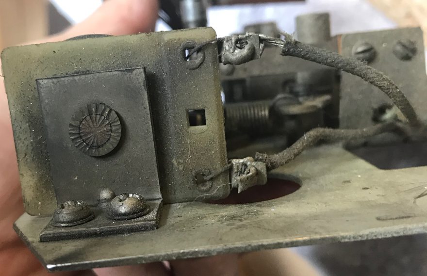
Prior to removing the coil stops, look on the other side of the stepper and see if there are any nuts on the back of the screws. In one case, there maybe a plate held in place by these nuts. That is the ‘window’ for the wheel to the front glass. This will need to be aligned to display the number of games left when it is reinstalled. Remove those nuts and the plate.
 Clean and shine up the side of this plate that is visible through the window. We use the buffing wheel with a Dremel plus the same Mothers Mag & Aluminum Polish used to clean other EM parts. Wipe with isopropyl alcohol. Then apply a light coat of wax. This will look great through the backglass.
Remove the coil stop. This will free up the coil and plunger. Inspect the wiring and fix it if needed. Clean the plunger and coil sleeve with isopropyl alcohol.
Lubrication
Clean all the old grease off of the linkage, plus the grease on the stepper plate and rocker posts. Also clean all the grease off of the center ‘gear’.
Check to see that the wheel spins freely. We try not to remove that wheel. If it does not move freely, try rinsing where the shaft goes through the bracket with isopropyl alcohol. That usually frees it up. Then oil lightly with sewing machine oil.
Add small amounts of teflon or Super Lube grease to those same spots. Add a tiny amount to where the linkage meets the plunger, but be very careful to not get any into the plunger that goes into the coil. This step maybe easier to do after it is all reassembled.
Reassembly
 We usually just start in the reverse order. Install the plunger into the coil, hold the coil in place, position the coil stop and tighten the screws. Do this for both coils.
Check your earlier photos and position the rocker arms / linkage onto their posts and into the plungers. These two must be positioned properly to work together, so that the wheel will advance and step back.
 If the point where the plunger and rocker arm was not lubricated earlier, lightly lubricate it now, being careful to not get any into the plunger that goes into the coil.
Select the (usually 3) springs and reattach them to the rocker arms.
Insure that the wheel is returned to the zero position. Wind the center spring the correct number of turns and reattach it to the post.

Don’t forget that shield that is attached, usually, to the back of the coil stop. Set the game wheel to zero, as far back as it will move. Then add “1” game. Position the shield to show that one game. The shield should be positioned close to the wheel, but insure that it is not rubbing against the wheel. Tighten the two nuts that hold the shield.
Back the wheel to zero (or no) games and insure that no number shows through the shield. Then add one game and insure that the “1” is seen and roughly centered.
Checking for Proper Operation
‘Snap’ both solenoids, one at a time. Check that the wheel counts up to the maximum number of games. Then snap the other solenoid down to zero. Make sure it moves freely each time.
The Switches
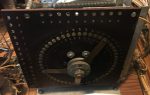
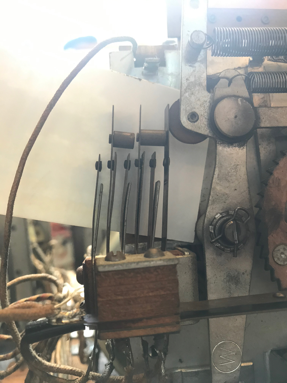
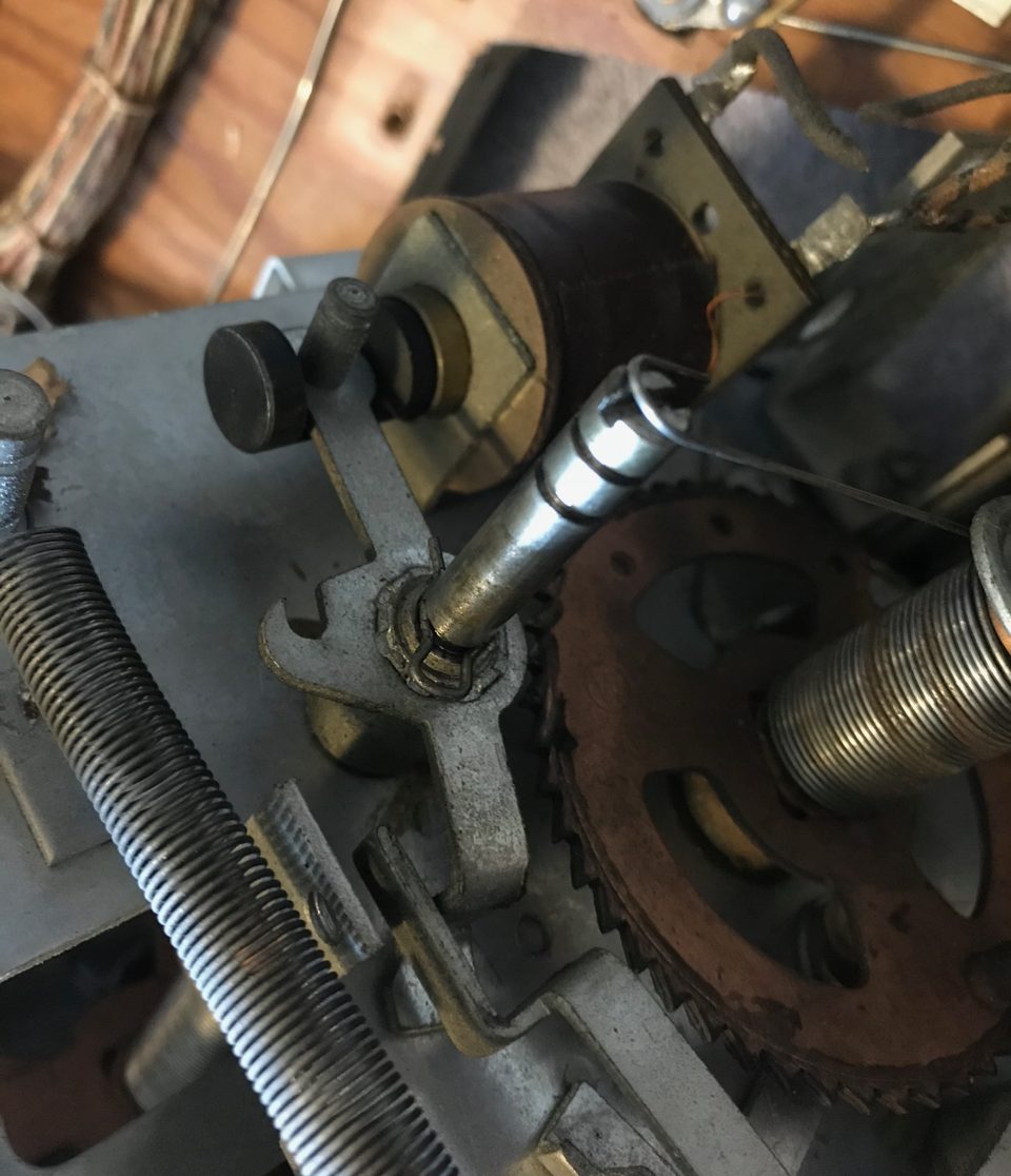
 There are usually just two pairs of leaf switches. One switch turns off the game start relay when there are zero games on the credit wheel. The other switch turns off the add credit solenoid when the maximum number of games is reached. Sometimes these two switches are mounted together, as in our example.
Note that the switch contacts should be cleaned following the steps outlined in the switch adjustment page.
In this picture, the game start switch is the top switch. The switch to turn off the add a credit game solenoid is the bottom switch.

There are sometimes two different posts on the gear wheel. The one post is always set to hit the game start relay switch at zero. The other one can be moved by the operator to set the maximum number of free games. In our situation, there is only one post. The maximum number of free games is 47!
Setting Free Play
Setting free play should be done now. By ‘snapping’ the solenoid, set the number of game credits to zero (or none). In normal operation, the top switch would now open. Using your switch adjusting tool, bend the leafs away from the post, so that the switch stays closed. In the above two pictures, the credit game reel is retracted all the way to zero (or none). But the post is not pushing the top switch open.
Free play is now set.
Checking Stop Adding Credit Switch
The other switch stops the game from adding any further credits for games. Snap the solenoid to add credits. Insure that when the reel spins all the way around, that this other switch opens.
Finishing Up
 Reinstall the credit mechanism using the screws to hold it to the cabinet. Check for proper operation of this stepper. Usually the best way is to see if the game will start with zero games. Then add credits and see if the reel adds the credits.
Comments
Comments, including suggestions, improvements, errors, etc. are welcome (see below).
If you have a specific question about your game that does not directly apply to this page, please see our FAQ section.
Thanks for this. I had a sticky bonus wheel on a Bally Flip Flop (’76). I thought for sure the spindle of the wheel or something else “big” was making it stick. But simply cleaning off the pads and adding the slightest sheen of lubricant was the main thing that helped it start running smoothly again. Also glad I read the part about not messing with the springs, which apparently work fine.