A. Clearing the Playfield
1. Supplies Needed
2. Preparation
3. Clearing the Playfield
4. Removing the Ramps
5. Removing the Pop Bumpers
– Removing the Sling Shots
B. Cleaning the Playfield
6. Cleaning the Playfield
C. Repairing the Playfield (optional)
7. Playfield Repair
8. Fixing Inserts
9. Sealing Your Work
C. Rebuilding and Adjusting
10. Rebuilding the Mechanicals
11. Switches and Reassembly
12. Final Testing
This is a multipart series on how anyone can do a complete overhaul of your pinball machine and make it work like new.
Note that not all sections may be necessary with all playfields. For example, if there are not any problems with the inserts, you can skip that section. If not repairing the playfield, the touchup and sealing sections can be skipped.
The pop bumpers (or jet bumpers) are one of the most complex parts, maybe more so than the flippers. This is because of the lamp wires, the solenoid and the switches.
Many are tempted to leave them alone. If you really want a little short cut, leave the plastic body and lamp above the playfield alone. We can rebuild and clean the solenoid and switch which is under the playfield.
But the plastic parts get dirty, the ‘skirts’ get beat up and should be replaced. And it is a good idea to replace the spring holding the skirt up. And if these have the bayonet (round) bulb sockets, they should be replaced.
Warning: During the following steps, you maybe removing wood screws from under the playfield. They come in different size and lengths. Screws holding brackets to the playfield are generally longer than those that hold lamps and switches. When reassembling, using the longer one when the shorter one should be used could come through the top of the playfield. On some games, the copper colored ones are shorter and steel color are longer – but that is not consistent from game to game.
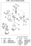
The Parts of the Pop Bumper
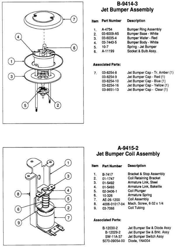 The pop (or jet) bumper on all pinball machines are essentially the same. The main interior body (4 in upper photo) is attached to the playfield by two wood screws. The bracket (1 in the bottom photo) is held in place by three nuts and the twist screws inserted flush to the playfield.
There are two moving parts above the playfield.
1) The ‘Bumper Wafer’ or skirt moves when a pinball hits it and activates the switch below the playfield.
2) The metal ‘bumper ring assembly’ is pulled down by the solenoid and ‘pops’ the pinball.
In the accompanying photo, the parts below the playfield are in the lower photo. The parts in the top photo are above the play filed. The ‘skirt’ sticks below the playfield as does the metal ring.
As mentioned above, it is possible to just remove the lower parts and rebuild them. But you should not as shown later.
Removal of the Parts Below the Playfield
This is the easy part! The first step is to remove the two nuts (photo 2) holding the metal ring which is connected from the solenoid to the parts above. Set these two nuts in your storage container.


If you have taken off the Pop Bumper Cap above the playfield, it should be possible to remove the ring assembly by lifting it up above the playfield. Set this metal ring aside. Repeat for the other rings.
Next, remove the three nuts holding the bracket in place (pictures 3 & 4). Set those nuts aside. The entire lower Pop Bumper Assembly should be loose. Remove this from the three screws.
It is possible to leave this assembly hanging from the two wires going to the coil. However, we usually use a zip tie to attach it to the nearby wiring harness.
Removal of the Lamp Socket
The most annoying part of working on the pop bumpers is removal of the lamp socket. This only has to be done if removing the above playfield portion.
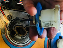
Inconveniently, the lamp socket is a wire an uninsulated flat wire ribbon. It is usually held in place by staples and has wires soldered to it. This has to be carefully removed. See photos #3 & #4.
Take photos of each wire connected to the flat wire ribbon. Be sure to get a photo of the color of the wire. Use a piece of masking tape and label the wire. Then unsolder the wires and set them aside.

Unless you have a pneumatic stapler handy, you will not be able to replace the staples. Most of the time, we lightly pry up or bend the center of the staple, so that the wire ribbon can be slid out. Remove as much as possible of the solder remaining on the wire, otherwise it will not pull through the pop bumper body.
Work the ribbons free from the staples. If there is a clear insulator, such as in photo #3, try to remove that. Save this insulation although we usually replace it with shrink tubing.
The lamp socket can be removed now, but we usually remove it with the upper body of the pop bumper.

An easier alternative is to just cut the metal ribbon and then plan on replacing it with a new bulb socket. This makes a lot of sense if it currently has a bayonet (round base) bulb socket as they lose the ‘spring’ and oxidize. But the 555 wedge sockets last almost forever. But these are ~40 year old sockets. We just cut the ribbon, and then pull the bulb socket through the base and replace.
Those bulb sockets with insulated wires are easier to deal with than the metal uninsulated ribbon wires anyway.
Note: If installing this new style lamp socket, it will sit higher than the original style. Most bulbs will then hit the pop bumper cap. It is important to replace the body of the pop as the new pop bumper body will sit a little higher and give room for the bulb.
Some shorter style LED bulbs will not have this issue.
Removal of the Above Playfield Pop Bumper Parts
 The rest of the removal process is easy. If you have not already removed the pop bumper cap, do so now. Remove the lightbulb.
The entire upper structure is held in place by two wood screws on either side of the lamp socket. Loosen those all the way. It is not necessary to remove the screws.
Carefully lift the upper assembly. There are two things still holding it in place: 1) the lamp socket ribbon working its way through the loosened staples, and 2) sometimes the upper body fits snugly in the playfield hole.
 Give a pull to break it free. It should not require much effort. If it does not move easily, check your work.
Once free, remove the assembly while guiding the pop bumper socket through the staples.
Don’t take this assembly apart just yet. Press down on the bumper wafer (skirt) on any side. Notice how the point in the bottom moves, then springs back up. It is crucial that this be re-assembled so it works this way.
Set this assembly aside. Be certain to remove the two wood screws inside the body and place them in your storage container.
Also remove the lamp socket from the pop bumper body. If this does not pull through the holes in the bumper body, you will need to remove solder from the ribbon. If not reusing this, you can cut off the ribbon wires at the bottom and pull the remaining lamp socket out.
This assembly will pop apart easily. If you do so, be sure to save the spring in the interior, if you plan on reusing it. There will be three parts (numbers refer to the first photo): 4) the main pop bumper body, 3) bumper wafer (skirt) – the part the pinball touches to activate the switch below, 2) the bumper base, and 5) the spring – and perhaps the lamp socket. The numbers refer to the parts assembly above.
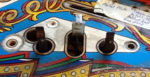
Inspect the Playfield

There are a few things to take note at this point. First, notice how much dirt was underneath the assembly. If there was not much, then you are lucky.
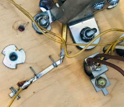
But more important, inspect the condition of the wood screw holes. Those in this picture show the condition of screw holes that were stripped. These are the two smallest ones on either side of the larger center hole. These will have to be repaired.
If not too badly damaged, the screw hole can be ‘healed’ by inserting a toothpick. A bit larger, and it may take more than one toothpick and some wood glue to hold it together.
Cases like the upper left one requires more extreme measures. Some people will drill it out to fit a small wooden dowel with glue. That is the most effective, but usually not required. We have used wood putty, but that does not drill and screw very well – but it can be done. Otherwise, it might be OK to use a mixture of wood glue and sawdust (and toothpicks if needed). We mention this now because these methods can require planning, plus the glue should set before reassembly occurs.
Remove the Remaining Above Playfield Parts
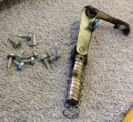
Flipper Bats
 We may have glossed over things like the removal of the flipper bats. These are held in place below the playfield with either Allen Wrench Setscrews, or Nuts. See rebuilding flippers for more information. Remove the rubber band around it. Many flipper bats are so discolored that they should be replaced. But some flipper bats have logos on them that are unique or worth saving.

The flipper bushings will stick up from the bottom of the playfield to the top. These can be left in place, unless you are planning on doing a clear coat. If so, remove them.
Note: While flipper bushings are held in place by just three screws through the threaded holes in the flipper bracket, there are sometimes nuts on the back, too. If you try to force remove those screws, they may break off. You should remove the screws holding the flipper bracket to the playfield first, so you can remove those nuts.
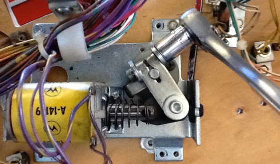
Slingshot (Kicker) Mechanism


Although we covered the removal of the slingshot plastics, the rubber rings and the plastic posts / hardware, we did not cover the removal of the slingshot and switches. This is done in a similar manner to the pop bumpers.
Photo #1 shows the kicker itself and the two switches. Photo #2 shows the four wood screws holding the solenoid bracket to the bottom of the playfield. Remove those – photo #3. It is better to tie this bracket to the wiring harness than let it hang. There is a spring on the coil plunger. Save that in your parts.

Photo #4 shows the kicker being held in place by (usually) 3 more wood screws by the mounting bracket. Remove those and the kicker will come free.
The two switches remain above the playfield. These are quickly removed by unscrewing the four (2 on each) wood screws.
Note the size and length of these wood screws as you remove them. When reassembling, if using the wrong ones, the screws may go through the playfield!