‘Special’ Solenoids in Williams System 3 – 7, 9, 11 and Data East
For information on the regular computer controlled solenoids, see this page.
 Note about solenoid coils: Solenoid coils, including Special Solenoids may or may not require a diode on a coil. Games before Big Guns (e.g., High Speed, Grand Prix, Fire!) require a diode on the coil. Games starting with Big Guns (and later System 11B/C games) have most diodes on the Aux Power Supply Board. Check your game to see if these diodes are there. If they are, your coil does not need a diode. Flipper Coils always need diodes. |
Standard troubleshooting steps are:
1) Insure that the coil has voltage going to and from it – both sides of the coil.
2) Check that there is voltage from the coil at the connector to the driver board.
3) Briefly short the connector or tab on the TIP122 / 102 on the board to ground to see if it fires.
Note: If shorting the tab on the TIP fires the solenoid, but none of the solenoids work during game play, it could be a problem with the Blanking Circuit – see below.
Problem: A single solenoid does not work. Could replace the TIP, the driver transistor, the IC, etc., until it is fixed, but with a digital probe and a little bit of knowledge, you don’t have to. In this example, solenoid 15 does not operate.
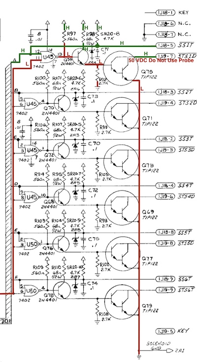
1) Check the manual to see which transistor drives this solenoid. In this example, we are looking at Q75, Special #1 for the left slingshot. For other games, look this page on the CPU board or the table for the solenoids.
2) With the power on, connect a clip lead to ground. Ground braid should do. Briefly touch the other one to the metal tab of the TIP transistor. The solenoid should fire. If it does not, there is a wiring / power / coil issue – fix that. If it does, there is a problem with the circuit.
3) Using a DVM, check for voltage between the TIP and the driver transistor (point A). If it is equal to the solenoid power (~ 50 VDC) you have a shorted TIP. Replace the TIP with a TIP102 and driver transistor (see wiring diagram). If you have a shorted TIP, you likely have fried the pre-driver transistor. If there is not 50 V DC at point A, then you might be able to replace just the TIP102 / 122.
If these steps do not work, it will be necessary to work further back into the control section of the circuit.
How the ‘Special Solenoid’ Circuit Works
The Special (or Switched) Solenoids
 Williams (system 3 – 7, 9, and 11, 11A and part way through 11B), plus Data East 1 – 3, have ‘Special Solenoids’. These solenoids are not controlled by the CPU, but via the switch through limited circuitry. Data East (DE) called these ‘Switched Solenoids’.
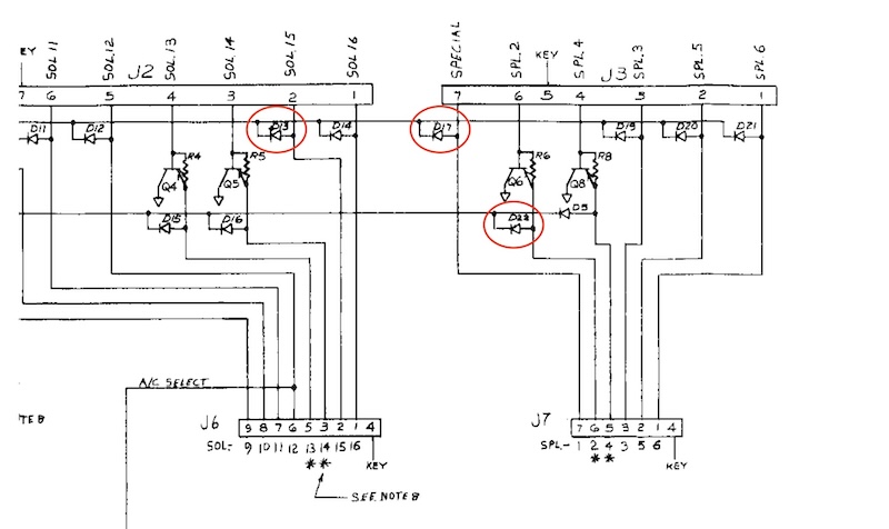
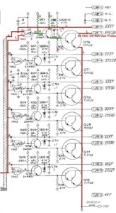
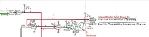
Usually these special solenoids include the slingshots (kicker) and pop (jet) bumpers. Occasionally, another solenoid or flasher might be included as ‘special’. On the above listing from a Williams High Speed, there are 6 ‘special solenoids’ – #17 through #22. The other solenoids and flashers – #1 through #16 are computer controlled solenoids.
Note: Williams and Data East later models did away with Special Solenoids and converted them to computer controlled, but still used these same circuits. If there is nothing plugged into 1J18 (Williams) or CN18 (Data East), then this circuit is no longer ‘special’ but is controlled by the computer, just like the other solenoids. But the logic circuit remains the same as outlined here with IC 7402.
The Blanking Circuit
Williams plus Data East have a Blanking Circuit. The purpose of this circuit is to keep the solenoids from firing if there is an issue with the computer signal. When the pinball machine is turned on, there is a moment before the computer ‘boots’. During that moment, the solenoids will all fire, without any instructions from the computer. To prevent the solenoids from all locking on, the Blanking Circuit sends out a low signal. This lasts for only a moment, then the Blanking Signal should go high.
If none of the solenoids work, it maybe a problem with the Blanking Circuit – although it is important to confirm that the solenoid voltage is working first. If all / most of the solenoids lock on for just a second at start up, then it is likely to be a problem with the Blanking Circuit.
For more about troubleshooting the Blanking Circuit, see below.
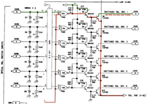
The Special Solenoid Circuit

In the Special (or Switched) Solenoid circuit, the solenoid is not activated by a command from the computer, but by a physical switch. On the pop bumper, that is the small switch located at the tip of the ‘skirt’ underneath the playfield. On slingshots, it is one of the two switches against the rubber ring.
When activated, those switch short to ground. This activates a logic circuit in the 7402 Logic IC, which turns on a pre-driver transistor and that turns on the driver transistor for the solenoid.
This process is supposed to be faster than a switch in the switch matrix that would feed into the CPU. The disadvantage of this process is that if the switch becomes stuck in the locked on position, it will lock on the coil which will then be destroyed. That may also destroy the driver transistor and sometimes the pre-driver transistor. On occasion, the 7402 logic chip will be destroyed too.
The 7402 Logic IC
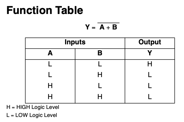
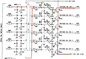
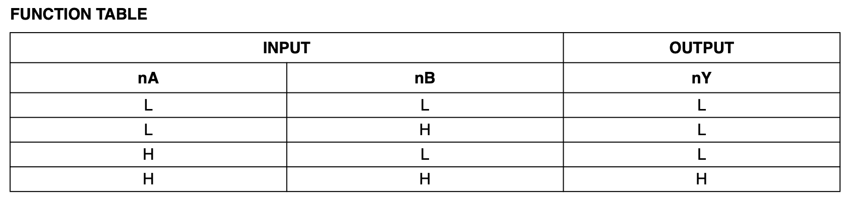
The input to the Special Solenoids have a 7402 Logic IC. For the output of this IC to turn on, both inputs have to be low (see logic table first row).
The blanking circuit goes high to enable the solenoids. But for the special solenoids, the blanking signal is inverted from high to low (referred to as the ‘EN Blanking’). So when the game turns on, the blanking output is high, then inverted and applied as low (L) to the 7402 IC.
The switch controlling the solenoid is held high (H) by a 4.7K resistor network. Given the logic table for the 7402 IC, both inputs have to be low for the solenoid to fire. Since the inverted blanking circuit is now low, all that has to happen to activate the solenoid is for the switch input to go from high to low. That happens when the switch is closed – it is shorted to ground.
For example, if the pop bumper ‘skirt’ switch is closed, we now have both inputs low, and the output of the 7402 goes high which activates the solenoid.
But if the blanking circuit is low (off), the input to this 7402 from the blanking is inverted to high, and the solenoid cannot be activated no matter what happens with the switch. If this happens, the blanking circuit is defective, or some fault condition exists and the computer is leaving the blanking circuit off.
Understanding the Special Solenoid Circuit
In the above drawings on the 7402 Logic IC:
* For Williams, input 11 is the blanking circuit that should be low; input 12 is the playfield switch for this solenoid.
* For Data East (DE), input 12 is the blanking circuit that should be low; input 11 is the playfield switch for this solenoid.
* For Williams 3 – 7, there is an additional IC on the input, a 7408. This IC essentially just passes the switched input through to the 7402. More on that below. Other than that, Sys 3 – 7 is similar to Sys 11.
Both the Williams and Data East special (switched) solenoids work in the same way. The blanking circuit is inverted from high to low, then applied to the 7402 logic IC (see section above). Following the logic table, for the output of the 7402 to switch, both inputs must be low.
It is important to understand the function of a pull-up resistor and a pull-down resistor. Without a voltage applied to a circuit, the voltage will float – be neither high nor low. This cannot be tolerated in a logic circuit. For a logic circuit to function properly, the voltage must be high (5V DC) or low (0V DC).
A pull-up resistor sets the circuit high (H – 5 V DC) and a pull-down resistor sets the circuit low (L – 0 V DC).
With one input to the 7402 high and the other low, the output of the 7402 is low (see logic table above) and the solenoid is off.
At rest, the input from the playfield switch (the pop bumper or sling shot) is high (H). This is held high by a pull up resistor (4.7K resistor package SR20 Williams, RA24 DE). The pull up resister sets the voltage high to the playfield switch plus one input on the 7402 IC. If this is not high, it maybe an issue with the resistor package SR20. Also check for bad solder joints and shorts in the circuit.
There is also a 560 ohm pull up resistor (R97 Williams, R19 DE) connected to the output of the 7402 setting the output high. When the output of the 7402 is low, the IC pulls the +5 V DC to ground. This is important to note in troubleshooting because if the 7402 output is not working, this output will default to high and lock the solenoid on.
When the switch on the pop bumper or slingshot is hit by the pinball, that shorts the +5 to ground. This shifts the voltage to the input to zero (L). The 7402 logic table states that with both inputs low, the output is now high (H). This turns on the pre-driver transistor 2N4401 and the TIP122 (or TIP102), shorts the control side of the coil to ground and turns on the solenoid.
Testing the Special Solenoid Circuit
Connect the Digital Logic Probe

An essential tool is the Digital Logic Probe. If you plan on doing any circuit work, you should have one. They are cheap and not difficult to understand.
Connect the red probe to a +5 source on this board, and the black probe to ground on this board. Setup the probe as outlined in the Digital Logic Probe section. If you don’t have a digital logic probe, you might be able to get enough information using a voltmeter set to 5 V DC. If auto ranging, it is suggested to set it to fixed range 0.0 V DC.
Determining the Part to Test
It is recommended to run these tests with the 50 V DC removed from this circuit. To do so, unplug 1J11, 1J12, & 1J19 (Williams 9 & 11) or CN11 & CN12 (DE). On Williams System 3 – 7, unplug 2J12, 2J11 and 2J9.
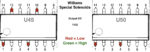
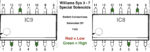
When testing with a Digital Logic Probe, the leg of the IC in Red = Low. Green = High.
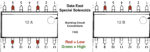
Data East Sys 1 – 3 7402 ICs 12A and 12B – Orientation Mark is on the Right
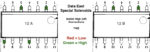
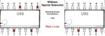
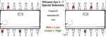
Williams Sys 9 – 11 7402 ICs U45 and U50 – Orientation Mark is on the Left
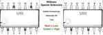
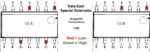
Williams Sys 3 – 7 7402 ICs U45 and U50 – Orientation Mark is on the Left
Blanking Connections to the 7402

Turn on the pinball machine and check the blanking inputs to the 7402. For Williams 9 – 11, it is U45, pins 3, 6, 8 & 11; and U50 pins 3 & 6. All should all be held low by the blanking circuit.
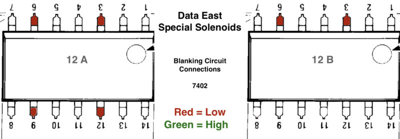
For DE, it is 12A pins 3, 6, 9, 12; and 12B on pins 3 & 6, which should also be held low by the blanking circuit.
On Williams 3 – 7, pins 3, 6, & 11 should be low on IC9; and on IC8, pins 11 and 8 should be low. On IC 8, pins 2 & 3 should be low, but these go to the flipper relay.
If all blanking connections are high, the blanking circuit is defective. If one does not read low, there is a break in the circuit board or solder point as all of these pins are electrically tied together.
Switch inputs to the 7402

The switch input legs – those connected to the switch on the playfield that controls the solenoid – all need to be positive.
The input legs on the Williams System 9 – 11 are U45 pins 2, 5, 9 and 12. On U50, they are pins 2 & 5.

The input legs on Data East are 12A pins 2, 5, 8, 11. On 12B they are pins 2 & 5.
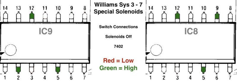
The input legs on Williams System 3 – 7 on IC9 are 2, 5, 12.
The input legs are controlled by the switch near the solenoid and all must be high – see above diagrams. If they are not, unplug the switch inputs (J18 Williams 9, 11; J13 on Williams 3-7; or CN18 on DE) and test again. If they are not high or they are floating, then the 4.7k resistor network or the 7402 is defective. There is also a zener diode (not on earlier Williams) meant to protect this circuit from accidental shorts to the solenoid voltage. If the switched input is stuck low, that zener could be shorted.
Outputs of the 7402

If all switched inputs from the previous section are high (previous section), then the outputs should be low.
Check the outputs to insure that they are low when the switch controlling the solenoid is open (off) and the switch inputs to the 7402 are high.

If any output is high, this should coincide with any locked on solenoid.
If all outputs are high, the 7402 is almost certainly defective and all the solenoids controlled by this IC would be locked on.

If one output is high, it could be the 7402, a defective 2N4401, or a bad connection. If the signal is neither high nor low, but floating, the 560 ohm pull-up resistor could be defective.

On Williams System 9 – 11, the outputs are U45 pins 13, 10, 4, and 1. On U50, outputs are 1 and 4.
On Data East, outputs are 12A, pins 1, 4, 10, 13. On 12B, they are pins 1 and 4.

On Williams 3 – 7, the outputs are on pins IC9, pins 1, 4, 13. On IC8, they are pins 4, 10 and 13. Additionally, pin 1 is used on IC8, but it does not change with the switched inputs.
The next portion of this test is to go back and check to insure that these outputs flip from low to high when the playfield switch is closed. This can be accomplished by manually closing the switch on the playfield. This should flip the input of the 7402 from high to low. And flip the output of the 7402 from low to high. See the section above, Understanding the Special Solenoid Circuit, for the switch inputs vs. the 7402 output.
Since the playfield switch just shorts the line to ground to turn on the solenoid, it might be easier to unplug the special solenoid switch input (Williams 9 – 11, 1J18; DE, CN18; or Williams 3 – 7, 2J13) and short that pin to ground using a clip lead.
Output of the 2N4401
Note: Prior to checking the output of the 7402, check it with the voltmeter. If the TIP is shorted, then there could be 50 V DC present here which could destroy the digital logic probe. If 1J19 or CN19 is unplugged, this should not be an issue.
If the output of the 7402 switches from low to high, that means that the input to the 2N4401 is also switched to high. That should cause the output of the 2N4401 to go high. If it does not, then either the 2N4401 is defective or the TIP is shorted to ground. It is possible that the 68 ohm resistor on the input (collector) is bad, but that is unlikely.
If the 2N4401 is defective, then it is likely that the TIP is defective. Or the TIP was defective previously and now the 2N4401 has failed. Generally, if the TIP is blown, we recommend replacing the 2N4401. They are both cheap and can easily be done while the board is out being worked on.
If the output of the 2N4401 switches but the TIP never turns on (or is always on) then the TIP is defective. Or there is a break in the circuit board.
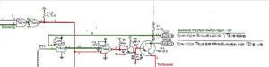
Williams 3 – 7 Difference
Early Williams 3 – 7 had a slight difference from the other systems here. There is an IC between the playfield switch input and the 7402. That is a 7408 (74HC08) at IC6 & IC7. This IC allows the solenoid to be activated by the playfield switch at the solenoid, or by the computer. As far as we know, the only time the computer activates these solenoids is during the solenoid test.
 If both inputs are high, that from the computer and from the solenoid playfield switch, the output is high. That is passed onto the switch input of the 7402 and keeps the solenoid off. If either input to the 7408 goes low, the output of the 7408 is low and that causes the output of the 7402 to go high and that turns on the solenoid.
The only time we need to pay attention to this 7408 is if the output which connects to the input to the 7402 does not change when the playfield switch is activated (grounded). In that case, the 7408 might be defective.
The Blanking Circuit
Background
On power up, these early SS (solid state) pinball machines would, for a fraction of a second, lock on all the solenoids until the CPU boots. If you are lucky, it is just annoying. But having all the solenoids fire at the same time will put a strain on the power supply and will frequently blow a fuse.
So Williams devised a Blanking Circuit. This circuit will momentarily shut off all of the solenoids. In a perfect world, the pin will start up silently. Then, when the game starts, the solenoids, controlled lamps and displays will be able to be activated.
When Data East entered the pinball business, their circuits ‘influenced’ by Williams designs and included a similar circuit.
What Can Go Wrong
Initially, the blanking signal will be low. This may last for a second or less, allowing the CPU to boot. Once the CPU has taken over control of the solenoids, the blanking signal will go high (4 – 5 volts DC).
If the blanking system malfunctions, either all the solenoids will fire on start up and a fuse may blow; or none of the solenoids will work.
If the blanking signal fails, this could be caused by any of the following failures:
* Timer chip (555 or 556).
* 1 uF cap.
* 2N4403 transistor.
* 7404 IC (least likely).
* In Williams Sys 3 – 7, the board interconnector – although other problems would likely occur too.
For system 11A, 11B and 11C, there are three LEDs (system 11 does not have these LEDs). The right one is the blanking circuit. It should be off momentarily when starting up, then turn on and stay on.
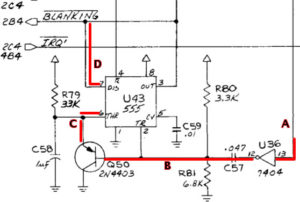
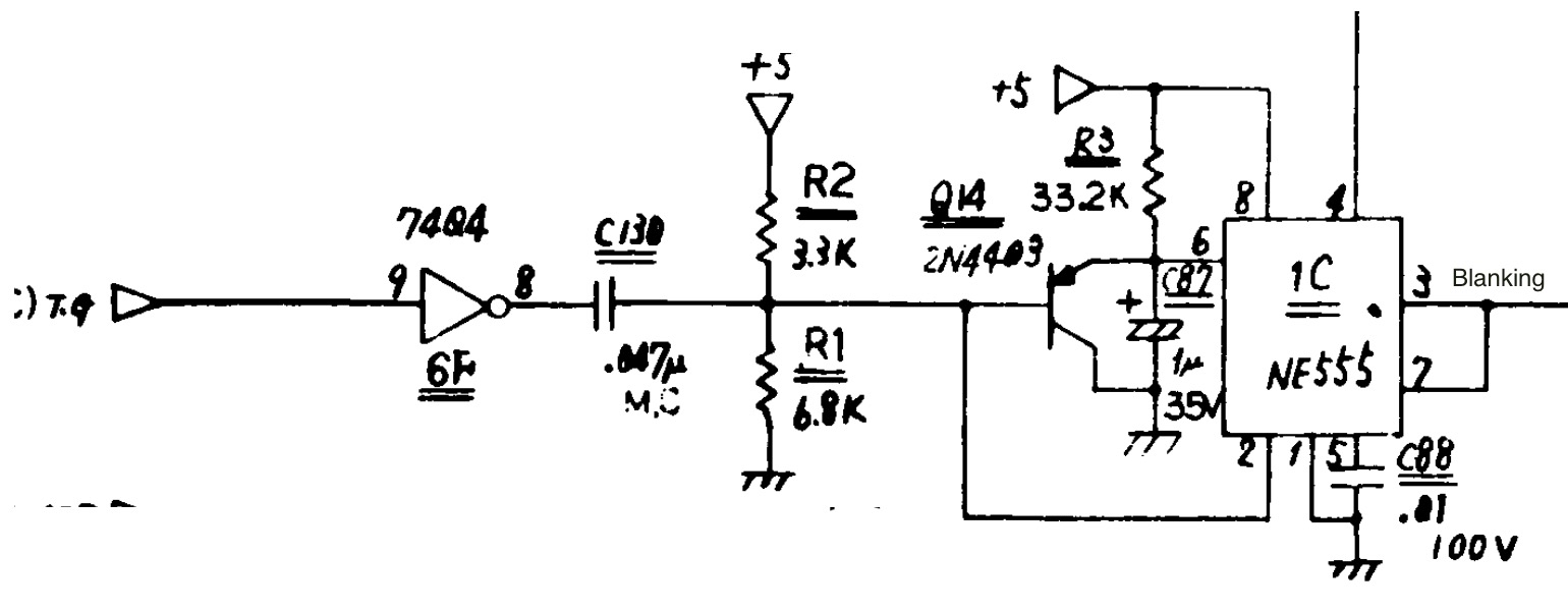
To find the defective component, the digital probe can be handy. Using the digital probe, it would be possible to see the signal change at U36 pin 13, then 12), onto Q50, into to pin 6 of U43 and out pin 7 to the solenoids.
Checking these signals with the probe is not easy since they should switch in the first second at start up. However, there is a trick for some. If you are lucky enough to have a CPU with a ‘CPU Test Button’ on the left side, leave the coin door open and press this button. The CPU will repeat a memory test and reboot. Connect the probe as outlined in step 4 above. The following states will occur when blanking is on (right LED on the CPU is on): A=high, B=low, C=low and D=high.
If testing when the pin is fully booted without this switch, the signals are a bit more confusing: A & B are high/low pulse, C is a low / pulse, and D is high.
External Resource
PinWiki – Blanking Signal Stuck Low
Sega Service Bulletin #57 – How the Blanking Signal Works
Using Transistors as a Switch – How NPN transistors turn on and off with digital input.