B. How Flippers Work
C. Serial Coils
D. Parallel Coils
E. Computer Controlled Flippers
Solid State Flippers
Parallel Coil Flippers
Note: It is recommended that “How Flippers Work” and “Serial Coils” be read before this section.
History of the development of parallel flippers for pinball machines is not well documented. As far as we can tell, parallel flipper coils were introduced sometime around 1983, when Williams pinball raised the flipper voltage to 50 V DC.
The Differences

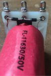
With serial coils, there are two wires to the center tab. With parallel coils, there are two wires going to one of the end tabs.
As of this writing, it is not clear to us if parallel and serial coils are wound differently, but it seems likely they are.
Parallel coils must have two diodes, because the two windings turn off at different times. Serial coils can get away with having only one diode, but sometimes have two anyway.
Note that the thicker wire is the power coil winding. The thinner wires are for hold.
How Are Parallel Coils Hooked Up
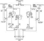
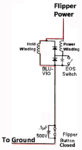
In the above photos (click on them for a larger image), the first image is that of a Williams pinball machine flippers schematic. It includes all the confusing wiring, including a lane change circuit.
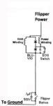
In image 2, we have stripped the circuit down to what is important: the cabinet flipper button (bottom of the image), the EOS Switch, the two diodes, then the power and hold windings of the circuit. Once the machine is turned on and and a game is started, power to the flippers is applied. The circuit is completed when the cabinet flipper button is pressed.
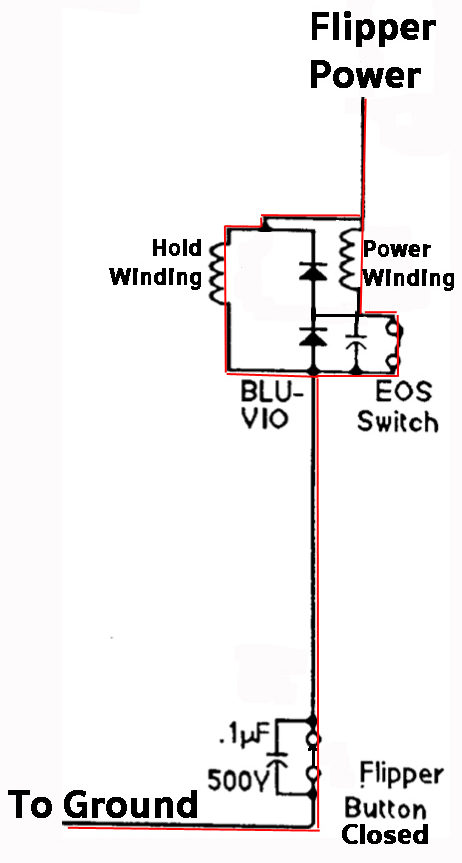
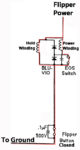
In the third image, electricity flows through both the power and hold windings. They are wired in parallel to each other.
This current flow happens only briefly. As the coil is energized, the plunger is pulled into the coil and the flipper mechanism moves, flipping up the flipper bat. Then something extremely important happens: The EOS switch (end of stroke switch) opens.
As the EOS switch opens, power is removed from the power winding, leaving the hold coil energized. Then two things happen: current flow drops and the power winding coil losing power acts like a generator, creating a potentially damaging ‘back EMF‘. To keep this generated voltage from destroying part of the circuitry, a ‘snubber’ diode (or ‘flyback’ diode) is installed. This diode shorts out the ‘back EMF’ power from the power winding, saving the circuitry.

Dropping the power is also crucial. If the EOS switch does not open, then high power will continue to flow. This will burn up the coil. But when the EOS opens, this high power is brief and the coil does not overheat.
When the player lets go of the cabinet button, power is removed from the hold winding and that second coil winding acts like a generator. So a second diode is installed to short out this ‘back EMF’.
Advantages of the Parallel Flipper Coils
It is possible that having both the power and hold coils on simultaneously will provide a bit more power with that initial flip. The extent of this is unknown by us.
However, some slow motion studies indicate that placing the capacitors across the cabinet flipper button and across the EOS switch decreases the spark. By decreasing the amount of spark, this significantly increases the life span of these switches and reduces the amount of maintenance.
While the use of parallel coils has significant reduction in wear and tear on the switches, a more significant improvement comes just a few years later, with the introduction of Computer Controlled Solid State Flippers. With this next system, only very low voltage and current flow through the switches virtually eliminating wear.
Troubleshooting Parallel Coil Flippers
Most problems with flippers can be resolved by rebuilding the flippers. But some problems can be a little more difficult to diagnose.
Flippers Lack Power
Check to see if it is a mechanical binding issue. See rebuilding the flippers. If it is not a physical issue, it maybe a worn EOS switch, an EOS switch that opens too soon, or a worn flipper button. Frayed wiring can also sap power.
Flippers Do Not Stay in the Hold Position – Chatter
Many reflexively think this is an EOS issue. It cannot be as the EOS switch removes the power coil from the circuit. The problem has to be in the hold part of the circuit.
Most of the time, this is due to a broken coil – where the wire in the hold coil is broken. Check the resistance of the hold winding. Sometimes a broken wire can be repaired by digging into the coil and pulling out a new section of the thinner wire and reattaching it to the appropriate tab. Most of the time, the coil needs to be replaced.
It is possible that the wiring to the hold part of the coil is broken. Inspect and replace.