This article was originally posted on PinballRehab.com.
Reproduced with permission from terryb.
Written by terryb
A. Basic Soldering Tutorial
B. Basic Desoldering Tutorial
– Supplies Needed
C. Tools for Advanced Soldering
D. Advanced Soldering Tutorial
E. Advanced Desoldering Tutorial
This is part four of a five part series on soldering. This article is specifically oriented towards advanced soldering techniques. It covers the techniques necessary to solder circuit board components and builds upon topics covered in the Basic Soldering Tutorial.
Required equipment is covered in Advanced Soldering Tools and Supplies.
Should I be Repairing Circuit Boards?
Only you can answer this question, but consider that board repair shops have reported the number of hacked (non-repairable) boards has increased dramatically since Clay put out his repair guides. Just as you wouldn’t buy a pair of hair clippers, decide you’re a hairdresser and cut your wife’s hair, the same is true of soldering.
Moving from soldering a diode onto a solenoid to doing board work requires a quantum leap in equipment, knowledge and experience. This article will provide the knowledge, but you will still need quality equipment and plenty of practice. If you’re not willing to make that commitment then just send the board our for repair.
In addition, if you can’t read a schematic well enough to test a circuit with a DMM after soldering you should not be doing board repair.

In Image 1 you can see the result of amateur repair work done on a Williams CPU. When I got the board, the switch matrix circuit would only work when I pressed down on the IC in question. Once I got the chip off I found the previous “repair person” had destroyed 7 pads/through-holes and four traces. Although pretty amazing, this is not at all uncommon.
Circuit Boards
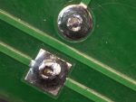
 Most circuit boards since 1980 use through-hole technology. This allows traces to be located on both sides of the board and when conductivity is needed from one side of the board to the other a through-hole is used (see image to the right). When a connection to a component is only needed on one side of the board, a pad is used rather than a through-hole.
The through-hole, or pad, is actually one physical part and the board trace a second physical part. They are electrically connected once the board is wave-soldered. It is not uncommon for the connection to break right at the point where the through-hole, or pad, is soldered to the board trace. It is also not uncommon (especially after someone has hacked the board) to find a pad destroyed or the metal liner in the through-hole damaged.
Soldering Theory
There are four important stages that occur while soldering: cleaning, melting, flowing and wetting. The first step, cleaning, occurs because the rosin core of the solder melts and flows at a lower temperature than the solder. The cleaning continues throughout the soldering process as solder, and therefore flux, continues to be added to the joint.
Note: If solder is applied directly to the tip of the iron, the flux will vaporize instead of flowing across the joint and cleaning it.
The next stage is when the solder melts. For 60/40 solder this occurs between 361 and 374 degrees (the plastic range). For 63/37 solder this occurs at 361 degrees since it is eutectic (has a single melting point).
Next the solder begins to flow from a lower temp area to a higher temp area as you move it away from the iron’s tip. If you watch a good solderer you will notice they first place the solder at the point where the tip is touching the land (trace, circuit pad or through-hole) and then move it to the opposite side of the lead as the solder begins to melt. The initial placement of the solder against the tip forms a solder bridge which provides thermal linkage to transfer heat to the land and component lead.
Note: This is much different than melting the solder on the tip of the iron.
All of the following are required to get a good solder flow.
- The joint is free of oxidation.
- Good surface contact between the iron’s tip and the lead and the land.
- The temperature at the tip is higher than where the solder is applied.
When soldering a through-hole component you can briefly see the solder ball shrink as the solder flows to the other side of the board. The solder ball will also go from a convex ball to a concave ball at this point.

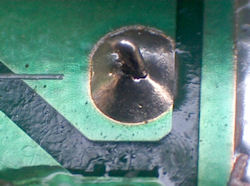
Our last stage, called wetting action, takes place when hot solder contacts copper and the molecules of solder and copper blend to form a new alloy. This action provides not only the electrical connection to the joint, but gives it physical strength. When a joint is oxidized, insufficient heat is applied or the tip of the iron does not have good surface contact with both the lead and the land, wetting action will not occur and you will get a cold joint (see Image 2).
Below 500 degrees you will not get proper solder flow and wetting action. In addition, due to the thermal capacity* of the soldering iron, a tip temperature higher than 500 degrees is required. This is why most professionals solder within a range of 650 – 700 degrees.
* The thermal capacity of a tip is the amount of heat it can hold.
Soldering Temperature
The following information is excerpted from a whitepaper written by Hakko Corporation, a leading supplier of soldering equipment (I have added the conversion to Fahrenheit).
As a general rule of thumb, the optimal soldering temperature should be high enough so that when making a solder connection, the solder is approximately 50°C above its melting point. The set temperature for a soldering station should be an additional 70°C to 100°C higher to provide a heat reserve for the quick thermal recovery of the tip after the solder connection is made. The performance of the soldering station used and the type of solder used will determine the optimal soldering temperature.
For example, lets look at the melting points of common solders:
- Tin/Lead (Sn63/Pb37) – 183°C (361°F)
- Tin/Lead (Sn60/Pb40) – 190°C (374°F)
- SN100 (Sn) – 232°C (450°F)
Now let’s add the 50°C we need for making a good solder connection:
- Tin/Lead(63/37): 183°C + 50°C = 233°C (451°F)
- Tin/Lead (60/40): = 190°C + 50°C = 240°C (464°F)
- SN100: 232°C + 50°C = 282°C (539°F)
We now need to consider the type of soldering station we are using. If we are using a Hakko 936 Soldering Station (replaced by Hakko 888) which has very good performance, we should add approximately 100°C as the heat reserve for quick thermal recovery. The resulting temperature settings are:
- Tin/Lead (63/37): 233°C + 100°C = 333°C (631°F)
- Tin/Lead (60/40): = 240°C + 100°C = 340°C (644°F)
- SN100: 282°C + 100°C = 382°C (719°F)
Now let’s look at the optimal temperature settings if we were using a high performance soldering station such as the Hakko FX-951 Soldering Station. Because of the performance of this soldering station and the thermal recovery performance of the composite tips, we only need to add 70°C as the heat reserve for quick thermal recovery. The resulting temperature settings are:
- Tin/Lead (63/37): 233°C + 70°C = 303°C (577°F)
- Tin/Lead (60/40): = 240°C + 70°C = 310°C (590°F)
- SN100: 282°C + 70°C = 352°C (665°F)
Note: These are theoretical numbers. In reality, as discussed previously, most professionals run slightly higher soldering temps.
There are three lessons to learn from this information. First is the importance of a good soldering station (which allows you to solder at lower temps). Secondly, using lead free solder is disadvantageous since it requires much higher temps and therefore increases the chance of damaging boards. Lastly is to understand why you should ignore people who brag about how they solder at 500°F.
Personally, I use a Weller WESD51 Digital Station (equivalent to the Hakko FX-951) and most of the time solder at 650°F.
Temperature Management
There are a lot of myths about soldering temperature. Some will say the lower, the better, but too low a soldering iron temp will result in cold solder joints and longer dwell times. On the other hand, too high a temp will potentially damage components or traces. The bottom line is that temperature management is more important than the soldering tip temperature.
 Temperature management is calculated as the soldering iron temp times the dwell time. Electronic components are generally designed to handle 650 degrees for 10 seconds. That’s more than twice as much time as you should need to solder a connection, so how do components get blown by overheating?
Other than bad soldering habits, the most common cause is not considering the internal wiring of an IC, for example (see the image to the right). If you use a temperature of 700 degrees, take 3 seconds per lead and solder pin 1, then pin 2 and then pin 3, you have just applied 700 degrees to the individual NOR Gate for 9 seconds.
To avoid this you should always alternate pins rather than soldering them sequentially. Start with pin 1 and solder all of the odd pins then start over at pin 2 and solder the even pins.
Pre-Inspection
Always inspect the land for damage. As mentioned previously it is not uncommon to get hairline cracks at the point where the pad or through-hole connects to the trace. Hairline cracks are often hard to spot so a magnifying glass is recommended.
Always test any through-holes from one side of the board to the other to make sure there is conductivity. Damage to through-holes is not always visible and will keep solder from properly flowing from one side of the board to the other.
Any damage must be repaired before installing the new component.
Preparation
The next step is to select the proper tip for the job. The two considerations are size and shape. I typically use a chisel, or screwdriver, tip in the following sizes: .0625″, .125″ and .187″. I use them, from smallest to largest, for IC’s and small transistors, larger (driver) transistors and bridge rectifiers.
 You should always size the tip to the job to provide optimum surface contact, good temperature control and avoid overheating sensitive components or traces.
Note: Most soldering stations require re-calibration when tips are changed.
Enemy Number 1 of a good solder joint is oxidation. It occurs when oxygen comes in contact with metal, and the process is amplified by heat. The more oxidation present–and it will be in a twenty some year-old game–the harder it will be to solder and the more likely you will get a cold solder joint.
Removing oxidation is a two step process: mechanical and chemical. First use a fiberglass pen to clean the land. The metal should be nice and shiny after cleaning. The second step, chemical, will occur when you add rosin core solder to the joint.
Soldering
Finally, we’re ready to do some soldering. Set your temperature controlled iron between 650 and 700 degrees and let it come up to temperature.
Tip: Wait another 10 minutes after the iron says it’s at temperature to let all of the metal parts of the iron, not just the temperature probe, come up to temperature.
Before soldering always clean and tin the soldering tip. Apply some solder to both sides and then wipe the tip on a brass tip cleaner (looks like a Brillo pad). Clean the tip fairly frequently while soldering to remove excess solder and oxidation.
At this point you can add some flux to the joint(s) if you so desire. It doesn’t take a lot.
 The key to soldering is placing the iron tip in the right location and getting maximum surface contact between the iron and the land and the lead. This is why conical tips suck, you can’t get enough contact area between the tip and the joint. The iron should be held at about a 30 degree angle to the board. Do not press down with the flat side of the chisel tip on the land, as this will more than likely cause the trace to lift.
In the image to the right you can see a crack around the lead where solder has not adhered. Either the lead was oxidized or the soldering tip was not firmly in contact with both the land and the lead while soldering.
Wait 1 – 2 seconds after applying the tip to the joint (the length of time depends on the size of the joint and surrounding material that will draw heat away).
Slowly feed the solder from the opposite side of where the soldering iron is placed. Initially, and briefly, place the solder at the joint between the soldering iron tip and the land. As the solder begins to melt move it to the opposite side of the lead from the iron’s tip.
Note: Do not use the soldering iron to melt the solder, you will get a cold joint.
 As you add solder it will form a convex ball and then when the solder begins to flow the surface of the ball will briefly, and quickly, shrink (as the solder flows through the through-hole to the other side) and become slightly concave. Once the solder is flowing, add a little more solder until you have good coverage and you’re done.
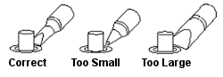
The image to the right shows examples of too little, too much and the correct amount of solder. While this picture is for a pad the same theory applies for a through-hole.
In the case of a through-hole, turn the part over and make sure the back side has flowed properly and the lead is soldered completely to the land. If not, put the soldering iron back on for 1 – 2 seconds and add a little solder, following all of the steps as described above.
Let the joints cool before continuing, if moved while warm you can end up with a cold solder joint. Do not use compressed air, flux or anything else to cool the joint faster. Clip the leads off slightly above the solder with side-cutters and then clean the area with flux remover (flux turns acidic after heating and must be cleaned off).
When you’re done, clean the tip, flood it with solder, clean it again and turn off the soldering iron. This will help protect and prolong the life of the tip. Do not clean the tip by dipping it into flux. I do this last cleaning with a damp sponge and the temperature set at 250 degrees.
Inspection
The most important step in the soldering process is inspecting your work. You will need to do a visual inspection and test all connections with a DMM. Do not skip this step. The pros don’t and that’s why they only pull a board out once and never, ever create new problems after replacing a component.

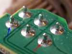
Use a magnifying lens and good lighting for the visual inspection. On a good solder joint the solder will conform to the individual components. For an example of what the joint should not look like, see Image 4 where the second resistor down looks like it’s been glued with crazy glue.
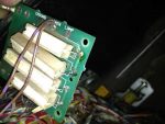
The solder joint should be shiny (leaded solder only) and smooth, slightly concave and have no pits, sharp edges or deep scratches (see Image 2, which fails every one of these criteria, and Image 3, which has 4 good connections and 2 bad ones).

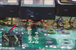
A photo from one of my favorite forum posts is shown in Image 5. The unnamed individual posted before and after pictures and was actually bragging about his solder job. Notice the two rectifier leads circled in red (the rectifier he replaced) and compare them to the blue circled lead. On both of the blue circled leads you can see where the solder did not adhere properly to the component leads.

Another curiosity arises if you look at the small before photo and compare it to the area the red arrow is pointing at. I don’t know if that’s due to excessive solder (like way excessive) or if he overheated the board and bubbled the green solder mask. Either way, nothing to brag about.
Curiously enough the circuit didn’t work after he replaced the bridge rectifier.
I always check my solder connections with a DMM after soldering.
Put the DMM in diode mode and test from the lead on the component you just replaced to the board trace (use a sharp test lead or needle to push through the green solder mask) or the component the trace connects to. If dealing with a through-hole, test from one side of the board to the other to make sure you have conductivity. Also check between adjoining pins ( pin 1 and pin 2, etc.) to make sure you haven’t formed a solder bridge across two pads.
Practice, Practice, Practice
There is nothing that beats practice. The best way is to find an old non-working CPU board from a computer and practice desoldering and soldering components until you’re an expert. While a lot of people recommend learning on some type of electronics kit, anyone can solder together a bunch of brand new components and on a brand new board.
You are much better off working with an older board that will be more similar to the challenges provided by a twenty some year-old pinball circuit board.
Re-Flowing Solder
You will commonly hear people talk about re-flowing, or re-soldering, a connector, IC ,etc. The basic re-flow technique is to clean the area mechanically, add flux to each pin and then heat with a soldering iron until the solder melts and flows. If you can’t get the solder to flow add a small amount of solder, which will create a solder bridge and aid in conducting heat.
The pros will often use a product like Aoyue 8032++ Hand Held Digital Hot Air Rework Gun to re-flow solder.
If you don’t have good joints after this you will have to desolder all the pins, clean the area mechanically, apply flux and then re-solder.
Video Notes
- The video is 30 minutes long, but is time well invested if you want to solder circuit board components.
- At 17 minutes and 50 seconds into the video you can see the solder ball shrink as the solder begins to flow.
- At 20 minutes into the video he explains how to solder by adding solder directly to the soldering iron. Many OEM’s use this technique because it’s fast (not because it’s correct). Most likely when using this technique you will not get proper wetting, so I suggest you avoid it unless you’re really experienced.
- You should not solder the pins on an IC sequentially as he does at 22 minutes into the video.
- Australian/English translation: “fill-it” = filet.
If you’re interested in soldering SMT components here’s a good video by the same guy.
Comments
Comments, including suggestions, improvements, errors, etc. are welcome (see below).
If you have a specific question about your game, please see our FAQ section.
Awesome repair information!
This is up there with the best with Clay Harrell’ pinrepair amd Chris Hibler’s pinwiki.
Is there a pdf version of the complete repair guide or even sections I can download?
Here’s a pin repair question.
I’m repairing a counterforce Gottlieb system 80. 4 digit credit/ball display works but all 6 digit displays are out?
The powersupply is putting out all the correct voltages to the mpu.
I guess a previous owner unplugged the display connections while the power was on. What TTL display chips would you suggests testing and or replace?
Cheers
Christopher Kelly
Thanks. We appreciate you comments.
As to a PDF, you might be able to print a page, then print it as a virtual PDF. Not sure how the formatting will come out, though. We need to look into that possibility. But PDF’s take a lot of disk space and could add to our hosting costs.
Unfortunately, we get rather overwhelmed with questions that are difficult to troubleshoot without being there in person. And we have obligations that we have to take care of first.
However, we do suggest you try to get a hold of a working display in order to insure that the problem is not on the CPU board. Or use a digital probe to confirm that all of the signals are present (careful, easy to burn out that probe by hitting a higher voltage).
So we cannot take the time to figure out your issues, Christopher. Sorry.
However, all is not lost.
Please visit our FAQ page.
https://homepinballrepair.com/index.php/faq-frequently-asked-questions-about-pinball-repair/
There are many people, who in their spare time will be happy to help you out. We would suggest the Facebook repair groups as they are quite active and usually helpful. If you don’t like Facebook, we still suggest that you join, not add any friends, get accepted to those repair grounds and just use that part only.
Thanks and we hope you understand.
The HomePinBall Repair Team.