B. Solid State Troubleshooting
1) Early Bally / Stern
– Voltages Required
– Solenoids
2) WPC Bally / Williams
3) Williams 11
4) Williams 3 – 7
5) DE – Sega – Stern
– DE / Sega V3 & 3B
– Sega / Stern Whitestar
C. EM‘s
This covers Williams Pinball Machines known as System 11, 11A, 11B and 11C. It also applies to Williams System 9 pinball machines which are similar to system 11. It involves checking the basic power supplies required for the system to boot.
If you are looking for specific information regarding the solenoids and possible blown transistor, check here.
Prior to starting, check the tools required and cautions.
Understanding the Layout
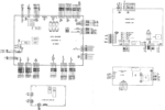
There are distinctive differences between the systems that complicate troubleshooting. System 11 consists of four boards: CPU, power supply, flipper power, and a ‘background’ sound board – but the CPU houses the main sound components. 11A moves the sound amplification from the CPU board and has a full external sound board. The last system 11A pin (Big Guns) added an Aux Power Supply. Some 11B and 11C have an interconnect board as well as the Aux Power Supply board. There are other significant differences between the systems that will not be covered here.
Voltages Required
All pinball machines require certain voltages to be present in order to work and System 11 is no different. There must be +5, +12 and ground present on the CPU board. If your CPU is getting these three connections, it should boot. Other boards such as display, and sound require other voltages.
When experiencing problems, the first step is ALWAYS to check for proper voltages. Without being certain that the voltages required are present, you cannot properly troubleshoot a pinball machine.
There is always the hazard that the voltages will be too high and a board can be damaged. It may be wise to disconnect the power to the other boards and concentrate on the power supply by itself, but this is not required.
We usually take a fine Sharpie and mark the plugs on their side with the plug number. But these plugs (should be) keyed and they are difficult to mess up.
Many of these connectors may not have a plug in them and do not require any action.
Power Supply Board: +12, +5 and Display
There are two variations of the main power supply board. The early models (High Speed to Swords of Fury) used the D-8345 board (see below). J6 supplies the CPU voltages. Early failure points on this board include the GI connectors that frequently burned. D-8345 is nearly identical to the Williams System 7 power supply, and replacement boards frequently work on System 7 through 11B.
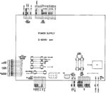

The next power supply, D-12246 was introduced with Taxi and was used on all subsequent System 11 production. This generation removed the GI power from this board and put the fuses in the interconnect board. Oddly, Williams decided to change the numbering of the connectors as J1 now supplies the CPU voltages. However, the circuit design is largely the same.
What can go wrong
1) Connectors (header pins and plugs), wires. Check to see if any look burned or discolored. If they do, replace both the pins and the plugs.
2) Board problems – voltage regulator Q5 2N6057, capacitors, rectifiers, etc.
3) C10 is old. It would be wise to replace it.
4) C8, 47 uF electrolytic can fail which will cause the +5 to run low.
Many of these problems can be easily fixed. The voltage regulator is easily replaced. Replacing the large electrolytic capacitor C10 and the bridge rectifier BR1 requires desoldering / soldering skills. Many of these boards have been damaged during attempted replacements, so this should not be attempted by beginners.
5) The high voltage section for the displays burns out frequently. If the +100 V fails, replace both transistors and both zener diodes. Same for the -100 V. Or just put in LED displays that do not require the high voltage and sell your displays.
To Isolate the Power Supply (Optional)
In a game with unknown voltages, a careful, conservative move would be to isolate the power supply from the other boards until you prove that the voltages are good. All plugs on the power supply have a prefix of ‘3’.
On first gen D-8345, unplug:
1) J6. Supplies +5 and +12.
2) J5. +100, -100 & +5 to the displays.
If you want the GI’s to stay off, unplug J9. For solenoids, unplug J3. Lamps are J4. The Power Supply Board does not supply these voltages – only the fuses are on this board, so this step is not required.
On second gen D-12246, unplug:
1) J1. Supplies +5 and +12.
2) J2. Supplies +100, -100 & +5 to the displays.
GI and solenoid voltage does not travel through this board.
Power Supply Board Voltage Readings
You should read the following DC values on the Power Supply Board. Except for the 5V, they don’t have to be exact. When possible, connect the black lead to ground on this board at TP2. All readings are V DC.
Caution: Extremely high and deadly voltages are present in the +100 and -100 V DC section. For qualified technicians only.
TP1 = +5 (4.9 to 5.2. Below 4.9 may cause rebooting. Above 5.2 might cause problems.)
TP2 = Ground
TP3 = +12 (must be above 10.5 – it can run higher than +14 or 15)
TP4 = -12 (can run -14 or -15)
High Voltages
There are no test points for the HV (high voltage).
First generation D-8345 plug & pin number (second generation D-122246 in parenthesis)
J5-4 (J2-3) = +100
J5-3 (J2-1)= -100
J5-1 (J2-5)= ground
J5-6 (J2-6)= +5
Troubleshooting the Voltages
5V and 12 V supplies
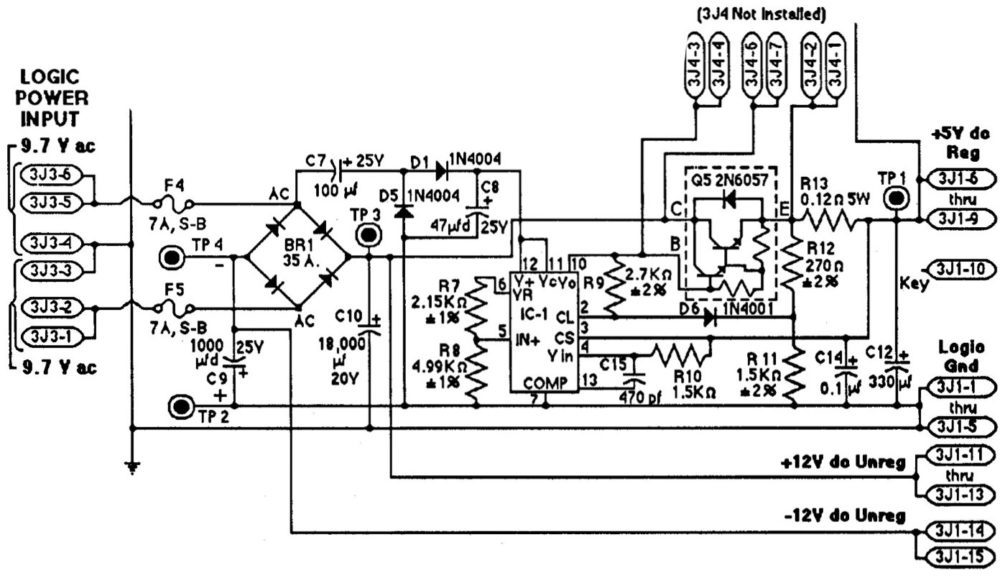
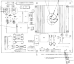
If TP1, the +5 is bad, and TP3 is good, then the problem is in the +5 voltage regulator section (which involves everything after BR1 / C10.
Q5, 2N6057 is far more robust than most 5V regulators, but it can occasionally go bad.
Check the voltages on the various components using the values on the next image. Visually check C8 and C7 and use a capacitance tester.
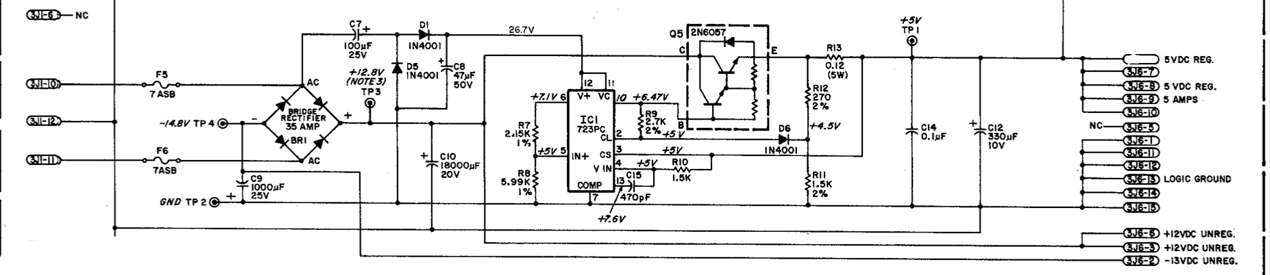
Check that 26 – 27V (nominally 26.7) is on IC1 pins 12 & 11. Leg 10 of IC1 should be 6.4V. If pins 12 & 11 read low, then C7 and or C8 are likely bad and the 5V power supply will be low. The diodes usually don’t fail, but check them.
We have seen it happen occasionally, that the 5V will run high. High voltage can destroy the ICs on the CPU board. If the output is high, check leg 10 on IC1. If it is also high, then IC1 may have failed.
While Q5 does not usually fail, if legs 12/11, 6, 5 and 10 are good on IC1, we would suspect that Q5 is bad.
If either IC1 or Q5 is suspected to be bad, it maybe a good idea to replace both. We also replace C7, C8 and C12 as those parts tend to fail.
If IC1 is removed, it is a good idea to check the diodes D1, D5 and D6 (using diode setting), plus the resistors R7, R8, R9, R10, R11 and R12 (resistance) and insure that C15 is not shorted (resistance). Those parts rarely fail, but it is a good idea to check them.
If +12 is bad, it is the bridge, BR1 (an open leg lowers the voltage while a shorted leg will blow fuse F5 or F6) or C10. If C10 fails by opening, AC rises too high. If C10 fails by leaking or shorting, then BR1 can fail and the fuses blow. Generally, if replacing BR1, one should replace C10 (and C9) also.
C9 is used to filter the -12. If that opens, AC hum will result, usually in the audio. If C9 shorts, BR1 may fail but F4 and/or F5 should blow.
If you need to replace BR1, C9 and C10 should both be replaced as they are getting old and dried out.
High Voltage Supply

In this power supply, the section that fails the most is the high voltage +100 & -100 V DC for the displays. This is actually two different supplies and usually only one side fails.
If F1 blows, check C1 on the +100 V and C3 on the -100 V supply. If you are lucky, one is bad and replacing that will fix the issue.
If F1 does not blow, but either the +100 or -100 has failed, replace both transistors and zeners on that side of the supply. If +100 is missing, that is Q1, Q2, ZR1 and ZR2.
If it is the -100 side, that is Q3, Q4, ZR3 and ZR4.
Might as well replace the 1N4004 (D3 or D4) with a 1N4007. Also replace the C1 & C3 150 uF caps that are getting old and dried out.
Or replace the old plasma DMD display with a new LED display, then sell your old plasma display. If you plan on holding onto this pin, that plasma display will eventually fail and they are not made anymore. Then pull F1 which will disable the HV supply AND put a label on that fuse holder to not put a fuse in (or remove the F1 fuse holder). A good idea to do the same to F2 and F3 if you have converted to LED displays.
The Other Voltages: Solenoid, GI and Switched Lamps
The previous section covered those parts of the power supply that are controlled on the Power Supply Board. But there are three more voltages required for proper operation of the game.
Note that Williams was constantly making changes to system 11 and it didn’t necessarily coincide with a change in designation from 11, 11A, 11B to 11C. For example, there is a separate flipper power supply in all system 11, and some 11A – but not all. An interconnect board was introduced the middle of 11B production and carried through 11C.
Solenoid Voltage and Switched Lamps

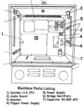
On System 11 and 11A, solenoid and switched lamp voltage is handled by two bridge rectifiers located on the backbox, and not on the Power Supply Board. Note that Williams made a serious mistake and did not install a fuse before these two bridge rectifiers. That means, if they short, the only fuse protecting the game is the main AC fuse. A short on one of these two bridge rectifiers can mean a fire and / or destroy the expensive power transformer.
Note that this is true of System 11 and (most?) 11A games, but check to see if yours has these. By the time 11B came out, there is a single bridge on the backbox and it should have a single 8A fuse on the AC side of this rectifier (but check!).
It is possible to install these two fuse holders, then cut and solder the incoming AC to those bridge rectifiers without adding any wire. We always like to label our modifications, especially since the correct values for these fuses are not in the manual.
| There is a modern alternative to these fuses that also replaces that large capacitor and adds a capacitor on the flippers. It is called the Inkochnito Bridge Board. The advantage is that you also get fuses plus new bridge rectifiers and caps. It is available at Pinball Life and Marco Specialties and several other suppliers. |
Note that there is a separate 50V Flipper Power Supply board on all System 11 and some 11A (Fire! and before) that will be covered below.
What can go wrong
The solenoid and switched lamp power supplies are pretty simple: AC comes into one of those two bridge rectifiers and exits as DC. If the DC voltage is absent, check the AC coming into the bridges. 13.5 VAC for the lamp circuit and 26 VAC for the solenoids. If OK, then the bridge is bad.
The bridge can fail shorted, in which case that fuse that as (hopefully) installed prior to the bridge will blow. But a part of the bridge (one leg or diode) can fail open. In that case, the DC voltage will be present but low.
The switched lamp power supply includes a large 30,000 uF capacitor that can fail shorted, but usually fails as open. Check for any leakage or deformation of this cap. Also check the AC on the switched lamp power supply. If present above a very low level, replace this cap.
The Power Supply Board does nothing to these voltages except put a fuse in the output. The solenoid and switched lamps come in, pass through a fuse, then exit. Check for any burned or damaged connectors or plugs.
The solenoid circuit adds two small capacitors and a varistor to the circuit as it passes through the Power Supply Board.
GI Power Supply
The GI Power Supply is nonexistent. It is just AC that comes out of the transformer. From here, there can be issues.
What can go wrong

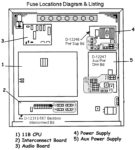
On early games, this AC passed directly from the transformer, into the Power Supply Board, through a fuse and back out. These connectors burned up. If burned, replace the plugs, and header pins.
In later games, Williams upgraded the quality / current capacity of the connector so it was less likely to burn. But the problem was not solved until Williams took the GI power off this board and sent it through the interconnect board. This board consists of upgraded connectors and four fuses for the separate GI sections.
Flipper Power Supply Board
 As mentioned earlier, System 11 and some System 11B machines have a separate flipper power supply board. This is a separate supply from the solenoid power supply contained on the main Power Supply Board.
The design is simple: 48 VAC comes into 15J1, through a fuse and into a bridge rectifier, is converted to DC, then goes out to the flippers.
What can go wrong
Pretty much just the bridge can fail. If it shorts, the fuse will blow. If the DC voltage is low, then a part of the bridge is bad. There are three connectors: 1) AC in, 2) ground, and 3) DC out. These connectors generally do not burn but can go bad.
Aux Power Supply Board
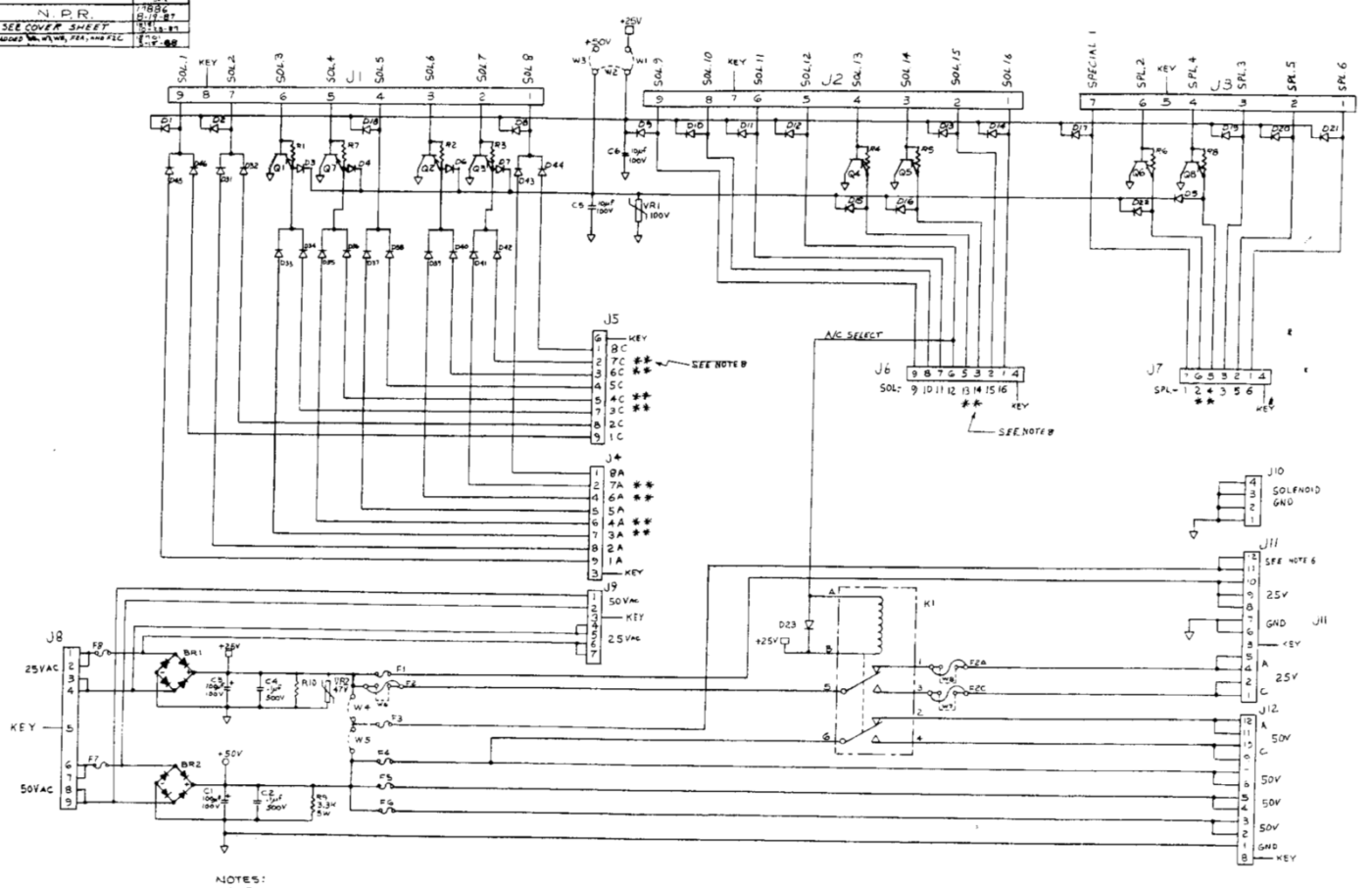 The Auxiliary Power Supply Board took over the function of the Flipper Power Supply Board, plus far more. It not only supplies the 50V DC for the flippers, but also 25 V DC for lower power solenoids. Each supply has its own fuse on the AC side, the bridge rectifier, small capacitors, and fuses on the DC side. There is also a varistor on the 25 V DC supply.
What can go wrong

Pretty much just the bridge can fail. If it shorts, the AC fuse will blow. If the DC voltage is low, then a part of the bridge is bad.
If one of the DC fuse blows, then the problem is not on this board, but where that DC is used, such as a solenoid.
There is also an ‘AC’ relay that can go bad and two more fuses. This relay switches back and forth from a solenoid and a flasher. If a solenoid fires when a flasher should, the problem is here. If the DC power is going into the relay but not out, then likely the relay is bad. If the relay does not activate, then either the relay is bad, or solenoid 12 on the CPU board is bad (or the connectors / plugs / or other CPU problem).
Note that when measuring these voltages, they will measure high when not under load (not being used). The 25V DC may measure 40 – 45 and the 50V DC may measure 70 – 75. That is just a sign that the 100 uF capacitor in the power supply is working. When in use, these voltages should drop down to their normal values. If concerned, measure the AC voltages at J8 on the Aux Board. Pins 1 or 2 and 3 or 4 should measure 25V AC (example, measure pin 1 and 3 – which ever ones have a wire going to them), while 6 or 7 and 8 or 9 will measure 50V AC.
If these AC measurements are off, it maybe that the transformer is not setup properly for your wall house voltage. Some people will choose a low tap connection in order to boost performance. That is a terrible idea.
Interconnect Board
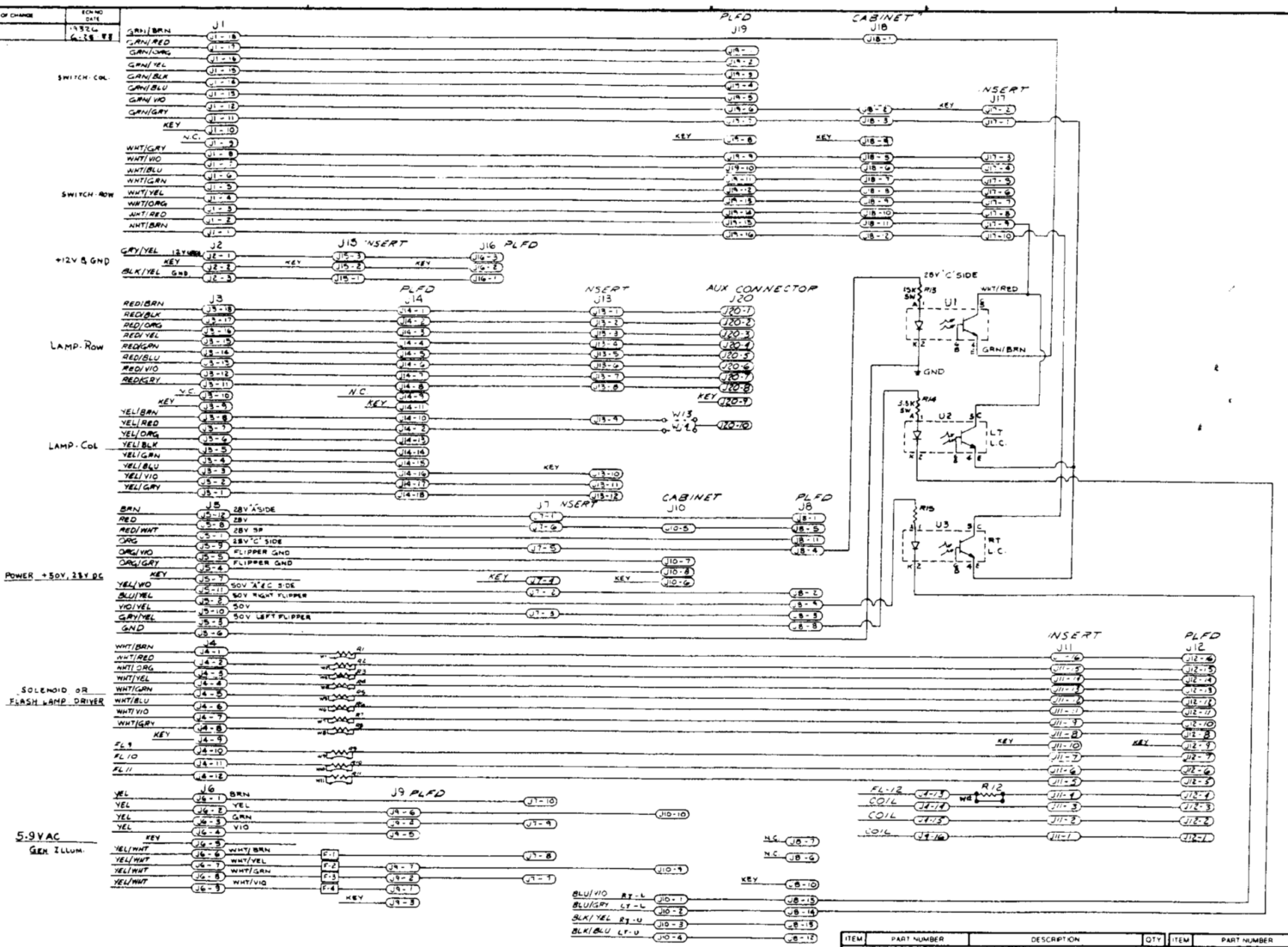 Interconnect boards eventually did far more than just route the GI power and fuse it. They included resistors to drop the solenoid power down for flashers, provided lane change optos (no more second switch on the flippers) and made it easier to ‘branch off’ the switch and lamp matrix with more connector positions. It also did the same for +50 V and + 28 V DC.
If some of these circuits work, but not others, check the connections and header pins on this board. But there is no power supply to check here.