B. Solid State Troubleshooting
1) Early Bally / Stern
– Voltages Required
– Solenoids
2) WPC Bally / Williams
3) Williams 11
4) Williams 3 – 7
5) DE – Sega – Stern
– DE / Sega V3 & 3B
– Sega / Stern Whitestar
C. EM‘s
This covers early Williams Pinball Machines known as System 3, 4, 6, 6A and 7. Note that system 7 uses a slightly different power supply. Later system 7 games have a separate flipper power supply board.
Prior to starting, check the tools required and cautions.
Note that Williams schematics of this era and difficult blurry and difficult to read. We did our best to find the best copies.
Important Notice
 Williams made a design mistake. When bridge rectifiers fail, they frequently short. Manufacturers typically install a fuse between the transformer and the rectifier so that if a rectifier shorts, the fuse blows. Williams did not do this.
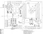
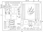
You should install this simple modification. Purchase two fuse holders and two 8A Slo Blow fuses. Install the fuse holders as shown in the photo. Cut the wires as shown and solder the wires to either side of the fuse holder. Install a label indicating 8A SB next to each holder.
Note that these rectifiers supply the +18 V DC switched lamp power and the +28 V DC solenoid and flipper power.
| There is a great alternative to installing these fuses. It is the Inkochnito Bridge Board. This board replaces the existing bridge rectifiers and the +18 lamp capacitor plus adds the require two fuses. It is available at Pinball Life and Marco, plus other suppliers. |
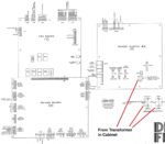
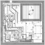
Understanding the Layout
The wall AC power comes into the transformer located in the cabinet, then to the backbox (head). There is a power supply and two rectifiers separate from the power supply. The voltages then travel to the MPU as well as the playfield solenoids.
The soundboard (if present) makes it own voltage. This layout simplifies measurements as all will be taken in the backbox.
Only three voltages need to be present for the machine to start (boot):
1) +5V DC
2) +12V DC
3) Ground
Additional voltages used by the game:
4) +18 V DC (switched lamps)
5) +28 V DC (solenoids and flippers)
6) +/- 100 V DC (displays – unless LED displays are installed)
7) 6.3 V AC (GI lamps)
8) +50 V DC (flippers on ~1983 and later games)
The other voltages have to be there for the game to play. But those do not have to be present for the game to boot.
To troubleshoot, the power flows as follows:
Williams did not make taking voltages easy. There are not any Test Points nor an obvious ground until later System 7 games. And even though boards lacked all the TP’s needed.
Note that we unplug connection to power boards to isolate them while under test, until we know the voltages are good.

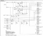

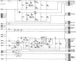
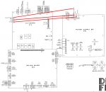
The main differences between the power supplies are that System 6 does not have GI fuses, GI relay nor GI connectors. That is because the GI power is not routed through this board. Prior to system 7, Williams used two discreet diodes in the +5 and +12 power supply. System 7 used a full bridge.
System 7 have the GI fuses, relay and connectors on the board. System 7 also has the +12V rectifier on the board (rather than mounted on the backbox), has a few test points (TP) and uses a different +5 power supply design. Later system 7 games had a +50 V DC flipper power supply added.
Note that the lamp and solenoid power is not generated on the power supply board but via those to rectifiers mounted on the backbox below the power supply board. The 13.5 V AC comes into BR1 and rectified to DC and filtered with the large 30,000 uF cap. The solenoid / flipper power supply is 25.5 V AC which is rectified by BR2.
If checking a fuse, be sure to follow this procedure.
Testing the Power Supply
What can go wrong
1) Main fuse is blown. Unplug the power, remove and check the fuse in the can in the cabinet.
2) Transformer fails. Extremely unlikely. Will be checked under voltages.
3) Connectors burned or fail. Common. Visually look for burned connectors. 3J1 and 3J2 burn is common.
4) Rectifiers fail. Common. Will be checked with voltage testing.
5) Board failure. Burned traces. Bad connector pins. Common. Will check visually.
6) Fuse blown. Common. Can be a bad fuse. Or another issue like a blown rectifier.
7) Voltage regulator fails. Common. If +5 is good, then the regulator is good.
8) Main +12 V capacitor gets old and fails. Replacing it is a good idea. C10 Sys 7. C15 Sys 3 – 6.
9) Almost the only failure for the lamp and flipper / solenoid power is the failure of those large bridge rectifiers. The large capacitor in the lamp power supply can fail, usually by losing capacitance.
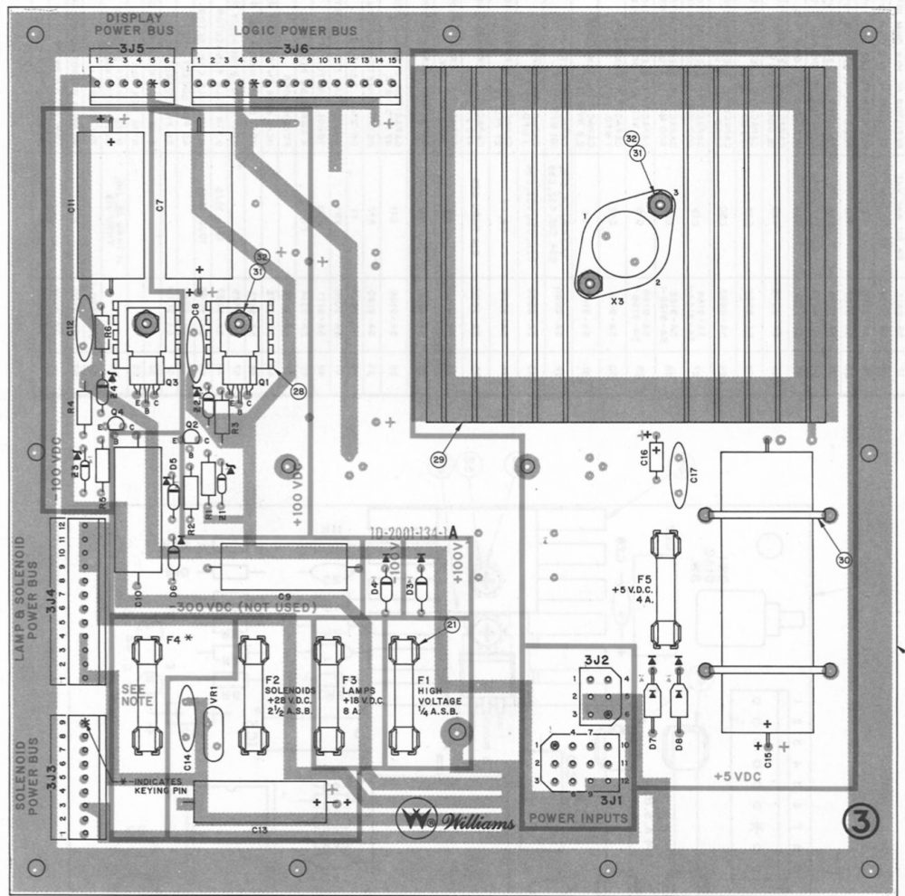
Systems 3 – 6
In order to check voltages accurately, it is important to use the ground on the board under test.
1) Turn the machine off.
2) Connect the black lead to ground. No TP for ground, so we use the next best thing. Clip to one of the following:
– The negative (-) side of C15 is ground.
– The negative (-) side of C7.
– The positive (+) side of C11.
– 3J6 pins 11, 12, 13, 14 and 15 are ground.
3) Unplug all plugs on the power supply board except 3J1 and 3J2.
4) Turn the power on.
5) Low Voltages:
+5V DC – 3J6 pins 7, 8, 9 or 10. +4.9 – 5.2V DC is OK.
+12V DC – Either side of F5 (this is unregulated so about 10 – 14V DC is OK).
6) High Voltages (see cautions).
+100V DC – 3J5 pin 4. Anywhere from +90 to 105.
-100V DC – 3J5 pin 3. From -90 to -105.
7) Solenoid power. Test each side of fuses F4 (flippers) and F2 (solenoids) vs. ground. ~28 V DC.
8) Switch lamps. Test the + side of the large 30,000 uF cap located on the backbox, below the power supply board. ~+18 V DC.
System 7

1) Turn the machine off.
2) TP4 is ground.
3) Unplug all plugs except 3J1 and 3J2.
4) Turn the power on.
5) Low Voltages:
+5V DC – TP1. +4.9 – 5.2V DC is OK.
+12V DC – TP3. This is unregulated so about 10 – 14V DC is OK.
-12V DC – TP4. This is also unregulated, so 10 – 14V DC is OK.
6) High Voltages (see cautions).
+100V DC – 3J5 pin 4. Anywhere from +90 to 105.
-100V DC – 3J5 pin 3. From -90 to -105.

7) Solenoid power. Test each side of F2 (solenoids) vs. ground. ~28 V DC.
8) Flipper power. Test 5J3 pins 1 or 2 for 50 V DC vs. ground. Note that early system 7 games do not have this board.
9) Switch lamps. Test the + side of the large 30,000 uF cap located on the backbox, below the power supply board. ~+18 V DC.
Troubleshooting the Voltages
+12, +5
System 3 – 6
If the +12 V is low, check fuse F5, diodes D7 & D8, connectors 3J1 and 3J2 (ground). Also visually inspect the large capacitor C15, and the smaller C16 & C17.
If +12V DC is good, but +5 is low or missing or quite high, suspect the voltage regulator X3 (LM323).
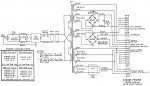
Williams System 7
 * If the +12 or -12 V DC is missing, check fuses F5 and F6 and connectors 3J1-10 and 3J1-11 that bring in the AC. If the large capacitor C10 is shorting, it should blow the fuses.
* If the +12 or -12 voltages are low, it can be a bad (open) bridge rectifier. A shorted bridge will blow a fuse. Test it using the diode tester. Also check for bad or cracked solder joints at this bridge rectifier on the board.
* Inspect C10 for the +12 and C9 for the -12. If it is leaking or bulging, replace it.
If the +12 V is OK, the problem is with the 5 V voltage regulator Q5 2N6057. Or IC1.
The 5V supply is controlled by transistor Q5 and IC1. This is a pretty reliable system. However, C7 and C8 failures are not uncommon with age. C14 and C12 are a little less likely to fail.
* If pins 12/11 are low on IC1, it is likely C8 or C7. This is a voltage doubler, so pins 12/11 on IC1 should be roughly double of TP3.
* If pin 10 of IC1 is OK, then it maybe Q5. If the +5 is still missing, test the transistor Q5.
* If one side of R13 has +5, but the other side is low, check C12. Less likely is a C14 failure.
* If the transistor is good, check pins 5, 4, & 3. If pin 5 is +5 and pins 4 or 3 are not, it is likely IC1.
High Voltage
The +100 and -100 display power usually involves replacing most of the components in that section. For example, if one transistor or diode fails, the others can be damaged. If either the plus (+) or minus (-) voltage is wrong or missing, turn off the power and check the resistance of the resistors. If off, you could try replacing them and see what happens. Otherwise, all of the major components in that section should be replaced. Both transistors (each half has two), and all of the diodes. The zener diodes are especially prone to fail.
Great Plains Electronics used to sell rebuild kits for these supplies, but, as of 2022, no longer do. However, their parts list serve as a great guide. This one is for Williams high voltage power supplies. It can be used as a rebuild guide, but be careful to compare the parts listed to those on your power supply board and substitute as needed.
+28 & +18
There is not much to the +28 and +18 V DC power supply other other than those two backbox mounted rectifiers and the connectors. The lamps have a large capacitor that can go bad. It usually does not short, but loses capacitance and can lead to flicker.
GI’s
The GI’s run directly off the transformer AC. If those lamps are out, look for burned connectors, a blown fuse, or a short / break in the wiring.
Testing the MPU Board
Unfortunately, there are many common problems with Williams 3 – 7 that can keep it from operating properly. But prior to troubleshooting, make sure the voltages on the MPU are OK.
What can go wrong
1) Connectors (header pins and plugs), wires.
2) Board problems – IC sockets. Leaking batteries.
3) Board interconnects. That large line of 40 pins and plugs between the MPU and the solenoid board has a high failure rate. If the right pin is not making contact, the game will not boot.
Many of these problems can be easily fixed. Great Plains Electronics sells the special pins for the board interconnects. And the IC sockets can be replaced, but doing so requires advanced repair skills.
Testing
1) Turn off the power.
2) Unplug all plugs on the MPU except 1J2.
Ground is 1J2 pins 1, 2 & 3. +12V DC is 1J2 pin 9. +5 V DC is 1J2 pins 4, 5, & 6.
+5 is also connected to the solenoid driver board at 2J8. Ground is 2J8 pins 1, 2, 3 &4.
+5 is 2J8 pins 6, 8 & 9.
3) It is a good idea to unplug the solenoid plugs on the Driver Board. Unplug 2J11 and 2J9.
4) Turn on the power. Test the +5 on C15 on the solenoid board. Connect the ground to the minus (-) side of C15 and the red lead to the positive (+) side. +4.9 – 5.2V DC is OK.
5) Move the voltmeter black ground lead to TP 10 on the MPU board.
6) TP 9 is the +5. +4.9 – 5.2V DC is OK.
6) +12V DC. Connect the red lead to TP1 on the MPU board. 10 – 14V DC is OK.
Final Step
If your voltages are good then:
1) Turn the power off.
2) Plug in all plugs except 2J11 and 2J9.
3) Turn the game on.
The game should boot and everything should operate except the solenoids.
4) If everything works, turn the power off.
5) Plug in all plugs, including 2J11 and 2J9.
6) Turn it on AND listen to insure none of the solenoids lock on. If this happens, you will hear a ‘thud’ as the solenoid plunger gets pulled into the coil and stays pulled in. Note that some games momentarily lock on the coils for less than a second on power up. That is not going to burn up a coil.
If a coil stays on, turn off the game immediately and troubleshoot. If left on, the coil may burn up.
Additional Troubleshooting
If the board still does not boot, there are a few quick things one can try.
1) Unplug the two boards from each other and plug them back together. This may remove some corrosion and allow the game to boot. If that happens, the fix is likely temporary and the connectors should be replaced.
2) Remove each socketed IC one at a time and replace it – in the same orientation! – making certain that all legs go into the socket. If this fixes the problem, it could be corrosion on the legs of the IC. If they appear black or oxidized, carefully clean the legs. It could also be the IC socket. Replace that socket.
There are now, finally, quality replacement boards available from here. Or send these out for repair. If replacing, don’t throw the old ones out. Let people who repair boards fix them and keep the originals in circulation.
Comments
Comments, including suggestions, improvements, errors, etc. are welcome (see below).
If you have a specific question about your game, please see our FAQ section.