WPC circuit designs were used in both Williams and Bally pinball machines from 1989 until Williams stopped making pinball machines in 1999. This run of games was arguably the most successful and sought after pinball machines ever made.
The descriptions below assume a WPC-89 machines. WPC-S and WPC-95 are similar, but the plug and TP numbers might be different.
Standard troubleshooting steps are:
1) Insure that the coil has 50 – 70 V DC going to and from it – both sides of the coil.
2) Check that there is voltage from the coil at the connector to the driver board.
3) Briefly short the connector or tab on the TIP102 on the board to ground to see if it fires.
Note: If shorting the tab on the TIP fires the solenoid, but none or a group of the solenoids do not work during game play, it could be a problem with the the trace from J113 to the CLK (clock) or OC input to the IC L33743. Those traces are tiny and easily damaged, especially if a electrolytic capacitor leaks. It could also be the ribbon cable from the CPU to this board.
Problem: A single solenoid does not work. Could replace the TIP, the driver transistor, the IC, etc., until it is fixed, but with a digital probe and a little bit of knowledge, you don’t have to. In this example, solenoid 15 does not operate.

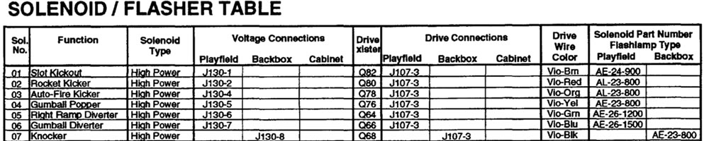
1) Check the manual to see which transistor drives this solenoid. In this example, we are looking at Q20 and Q19 for sol 28 in Williams 1993 Bram Strokers Dracula. For other games, look at the solenoid table. The schematic may be in the game manual or in a separate WPC manual.
2) With the power on, connect a clip lead to ground. Ground braid should do. Briefly touch the other one to the metal tab of the TIP102 transistor. The solenoid should fire. If it does not, there is a wiring / power / coil issue and not on this board – fix that! If it does, there is a problem with the circuit.
3) Using a DVM, check for voltage between the TIP and the driver transistor (point D). If it is equal to the solenoid power (~ 50 – 70 VDC) you have a shorted TIP. Replace the TIP with a TIP102 and driver transistor (see wiring diagram). If you have a shorted TIP, you likely have fried the pre-driver transistor 2N5401. If there is not 50 V DC at point D, then you might be able to replace just the TIP102.
If these steps do not work, it will be necessary to work further back into the control section of the circuit.
Prior to proceeding, be certain to familiarize yourself with the use of a digital logic probe. Logic probes are inexpensive. And they are easy to use once reading up on them.
WPC Flashlamp / Solenoid Theory
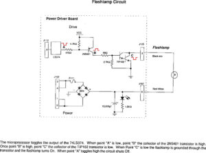
Both Flashlamps and Solenoids work in a similar fashion.
- Solenoids and flash lamps have power applied all the time.
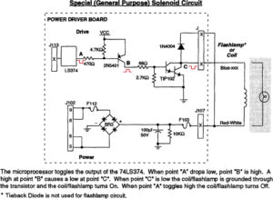
- The solenoids and flash lamps are turned on at the driver board. A transistor (typically a TIP102) turns it on by shorting to ground.
- The TIP is controlled by a smaller pre-driver transistor.
- The pre-driver transistor is controlled by a IC.
- The IC receives instruction from the computer (via plug J113 – the ribbon cable).
Troubleshooting with a Digital Logic Probe
An essential tool is the Digital Logic Probe. If you plan on doing any circuit work, you should have one. They are cheap and not difficult to understand.
1) After being certain that no high voltage is present due to a shorted TIP102, setup the digital probe as explained in “Using the Probe“. There are test points (TP) clearly marked as +5 and ground on the Driver Board. TP2 is +5 VDC. TP5 is ground. [Note that these test points are different on later WPC-95 pinball machines.]
2) Enter the service menu and the solenoid test (see the manual). Set the solenoid in question under repeat test fire.
Note that steps 3 – 5 can be reversed in order.
3) In this example, it is Q20 TIP102. Find the LS374 (U2 in this example) and test the leg with the probe at ‘A’. There should be a pulse every time the solenoid fires. If not, the LS374 might be defective. Other possibilities include the data lines D0 – D7, R22 and R23 (holding it high) or Q19 could be shorted to ground.
4) If OK, move onto ‘B’, the other side of resistor R22. If the pulse is not there, then R22 is open, the trace is broken, or R23 is defective.
5) Test ‘C’ at the output of Q19 2N5401. If missing, insure again that the pulse is on the input of Q19. If there and not at the output, Q19 is defective. Or, less likely, R25/R24 are bad, or the TIP base is shorted to ground.