The Bally 2518-32 Sound Board, was used in several early games. When these fail, one (of many) things that can fail is U9, the LM741. Sometimes, replacing that IC with a new one does not fix the problem. That is because Bally was using the LM741 out of spec.
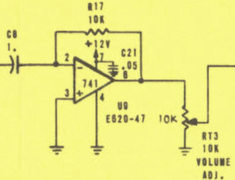
The LM741 is designed to run with a + and – DC supply. V+ should be on pin 7 and V- on pin 4.
In the Bally 2518-32 Sound Board, Bally grounded pin 4 and applied +12V DC to pin 7. The Bally board does not have a -12 power supply, so this appeared to be expedient.

In the -50 sound board, Bally simulated the + and – supplies by raising the input, pin 3 with a bridge resistor network, to about 6 V. This ‘makes the LM741 think’ that it has a +6 and a -6 power supply applied, since pin 3 (or 2) is the reference voltage.
If replacing a blown LM741 on a Bally 2518-32 sound board, it maybe necessary to make this modification. From some testing, it appears that Fairchild will not work, but National Semiconductor chips will work without this modification.
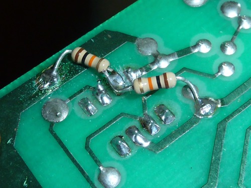 To make the modification, pins 4 & 3 are connected together, and the ground comes off of 4. Use a knife or a Dremel cutter to cut the trace between pins 3 & 4. Then solder two 1/4 W 10K resistors directly to the pin 3. Connect one resistor to ground and the other to +12. In our example here, we soldered these resistors to the back of the board where this is easily accomplished.
Additionally, solder a 1 uF cap on pin 3 of the 741, negative to ground, as shown in the -50 schematic.
With this modification, any LM741 will work on the -32 board, regardless of the manufacturer.
The original discussion for this has been archived on the Newsgroup, rec.games.pin and is accessible from Google Groups.