Cleaning and Adjusting the Gottlieb® Scoring Motor of an EM Pinball Machine

The score, or scoring motor is frequently the focus of problems in an EM pinball machine. On startup, it just keeps spinning. Or sometimes certain functions do not work. Most of the time, technicians attempt to identify and fix the contact that solves the problem. But a better way is to overhaul the entire score motor assembly.
The photo to the right shows the location of the large bolts that hold the plywood sheet to the bottom of the pinball cabinet. To remove the plywood for easy work on the mechanicals, it will be necessary to remove these screw bolts.
Note: Click on an image for a larger photo.
This is a new section. We are hoping for feedback on how it can be improved. Please let us know what else needs to be done. Thanks.
Getting the Gottlieb® (GTB) Score Motor to Work Perfectly
In order for the score motor assembly to work perfectly day in and day out, it will be necessary to disassemble the switches from the motor, clean and adjust every one. This will proceed faster than expected, because it is much easier to do this than troubleshoot an issue with the motor.
This procedure covers Gottlieb® (GTB) scoring motors. Instructions for Williams and Bally scoring motors are here.
Materials Needed
-
-
-
- Switch Adjusting Tool.
- Screwdriver – multi type is fine. Slotted and (sometimes) Phillips.
- 91% Isopropyl Alcohol. Not rubbing alcohol. Higher than 91% is not needed.
- Q-tips.
- Small rubber bands – random sizes.
- A Sharpie or similar. Fine tip.
Optional, but recommended:
- Dremel or similar.
And one or more of the following:
- Dremel polishing wheel .
- 1/8″ Carbon Steel Brush 443 for Dremel. Highly recommended.
- Dremel Sanding Brush Wheel (flap wheel).
-
-
Understanding How the Gottlieb® Score Motor Works

The GTB Score Motor is located below the playfield. It is the heart of the EM pinball machine and if the switches are not opening and closing at the right time, the game will not work properly.
To understand how to fix the Score Motor, it useful to know how it is setup.
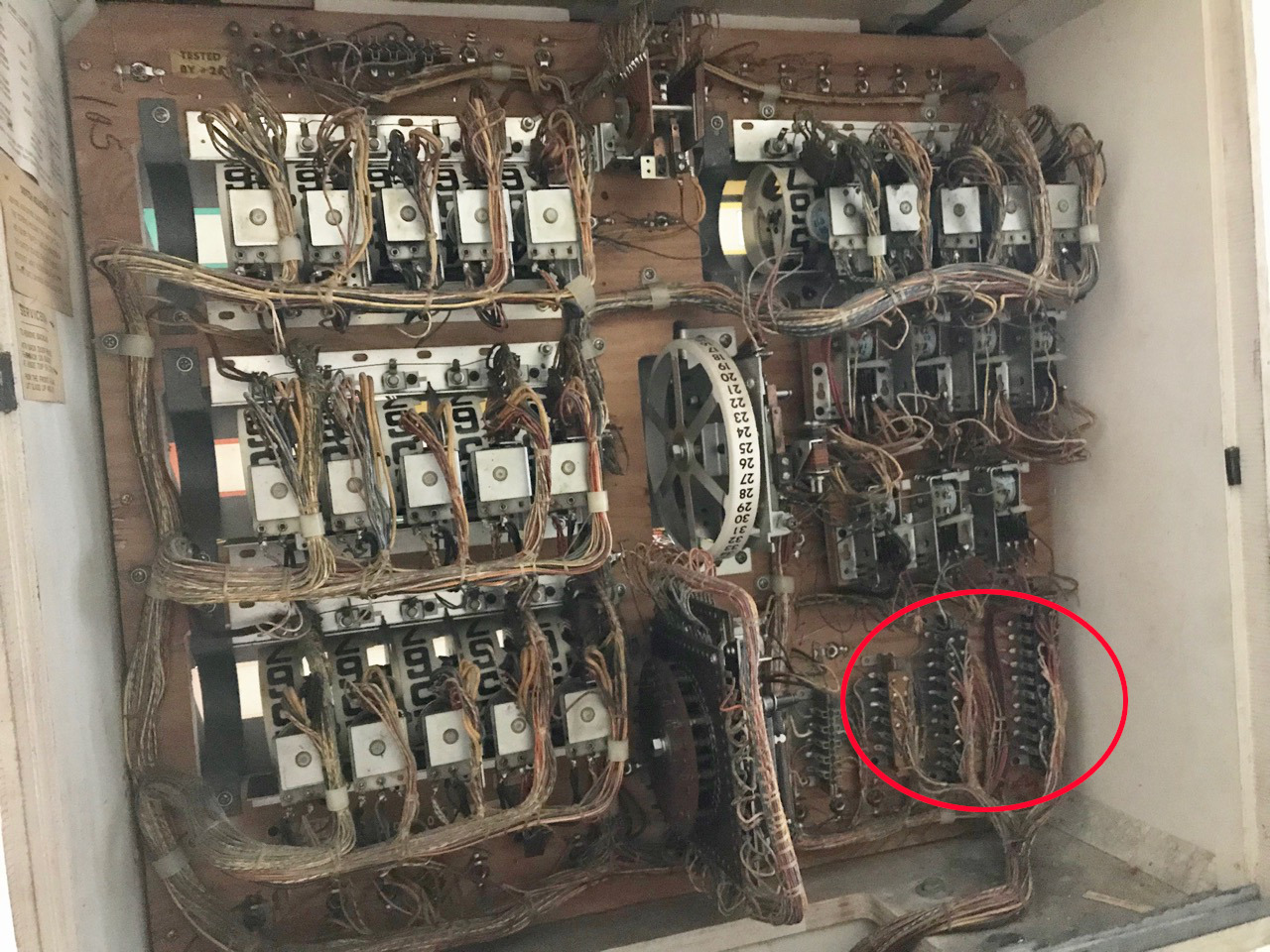
There are four switch stacks at locations 1 – 4 (see photo). These are referred to in the schematic diagram.

There are also 5 different levels, A – E, on the wheel. Level A pulses several times per turn. Level C has several different indents in the wheel and these typically act as stopping points when the wheel turns. The rest of the levels are posts.
Understanding How the Switch Stacks Work
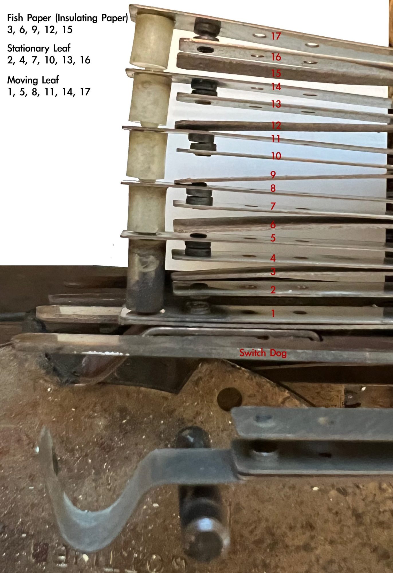 The leaf switch stack is made up of the following parts**:
*Copper leafs with a contact towards the end. Each set contains two of
–Stationary Leaf on the contact that does not move.
–Moving Leaf. One leaf that moves up and down.
This is the longest leaf.
*Several of these sets are usually placed on each other to create a Leaf Stack.
*Spacers that move Moving Leaf up and down.
*Paper Insulators (Fish Paper) that prevent electrical contact.
*At the bottom of the Leaf Stack is the Switch Dog.


The leaf switches in the scoring reel move up and down as the reel moves. Some of the switches make contact when the leaf is down, others when the leaf is up, and many make different connections when the leaf is up and down.
**We admit that not every pinball person refers to these components exactly the same. So we did our best to make this understandable.
GTB has pretty good schematics explaining what each switch on each stack does. In this example, the score motor from a Play Ball is displayed (which is what is being worked on in these photos).
Remove the Cabinet Bottom Panel
To make this easier, it will be necessary to remove the bottom panel from the game. This is made to be simple by the manufacturers.
Caution: Be certain to unplug the pinball machine from the wall outlet before proceeding.

1) Set aside a clean clear table to hold the bottom panel.
2) Unplug the ‘Jones’ plugs. There are usually a couple towards the back of the panel. Plus a few more in the wiring harness from the panel going up to the backbox. Pull up from the wafer. Do not grab the wires and pull.
3) Place plugs from the wiring harness coming from the bottom panel, down on top of the bottom panel. Also place the power cord on the panel.
4) There are two or more large screw heads holding the bottom panel to the cabinet (see first picture). Loosen all of them so that the bottom panel is no longer held to the cabinet.
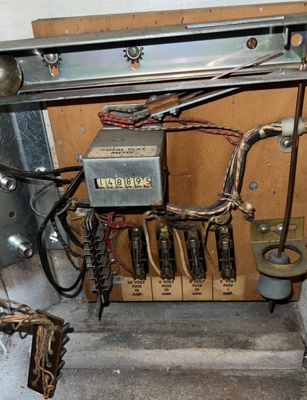
Unfortunately, GTB frequently did not install plugs to the other components in the cabinet. In this specific game, we had to remove several other components. Among the items was the power switch, and the assembly that houses several components (tilt, fuses, game counter) near the coin door. There is usually another Jones plug that comes from the coin door to that assembly, so be certain to unplug it.
Technically, it would not be required to remove the chimes as there are spade plugs to each coil. But we found it easier to remove the three top screws and lift that entire assembly onto our work area. The same is true with the flipper switches in that they can be removed or the spade plugs can be removed. The advantage of removing the flipper switches is that the contacts can then be cleaned.
5) Remove other items in the cabinet connected by wire cable to the bottom panel. Carefully place them on the bottom panel in a way that will not damage the other components.
6) While checking to insure all wires are free and all screws are loose, carefully lift the bottom panel out of the cabinet and place onto your work area. This will likely take two people.
Overhaul the Gottlieb® (GTB) Scoring Motor
Once the bottom panel is placed in your work area, position yourself along side the score motor.
Prior to proceeding, read the section on adjusting leaf switches. It is important how to adjust a leaf switch properly, so please read it. Also note the section on cleaning the switch contacts.
Note that, unlike playfield switches, there is not a stationary blade to hold the stationary leaf in place.
Removal of the Switch Stacks
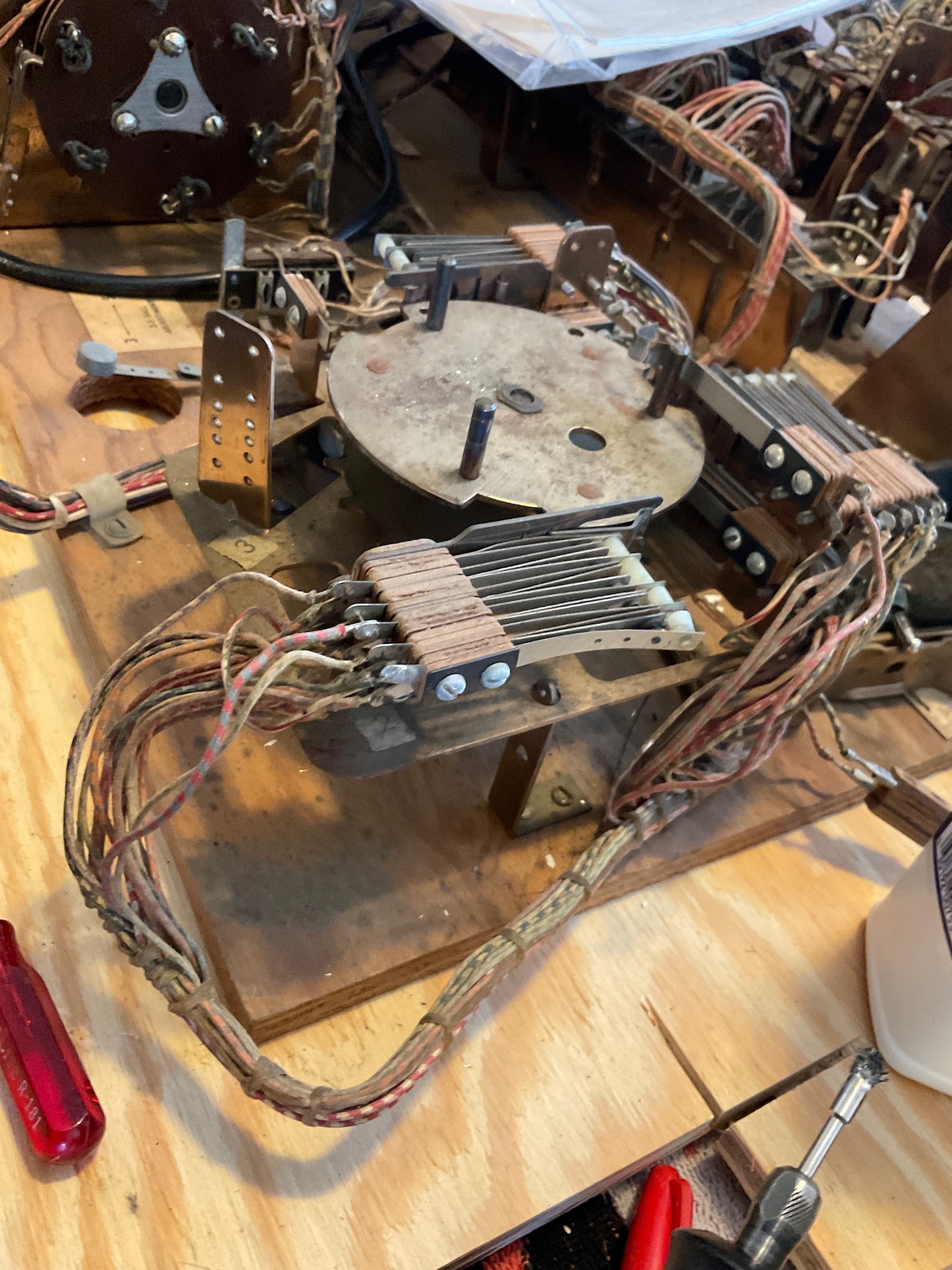
It is nearly impossible to adjust and clean all of the switch stacks while they are in position. To make this easier for us, we remove them.
Caution: The switch stacks are held in place with two screws and a small plate. While removing them, it is crucial to hold the switch stack together. On a rare occasion, the switches will come apart and it is best to avoid this.
Additional from Terry Dreyer: In some cases there are adjacent switches soldered together and/or a very thin jumper wire that is soldered from one lug to another. It is important to not break those wires / connections between switches.
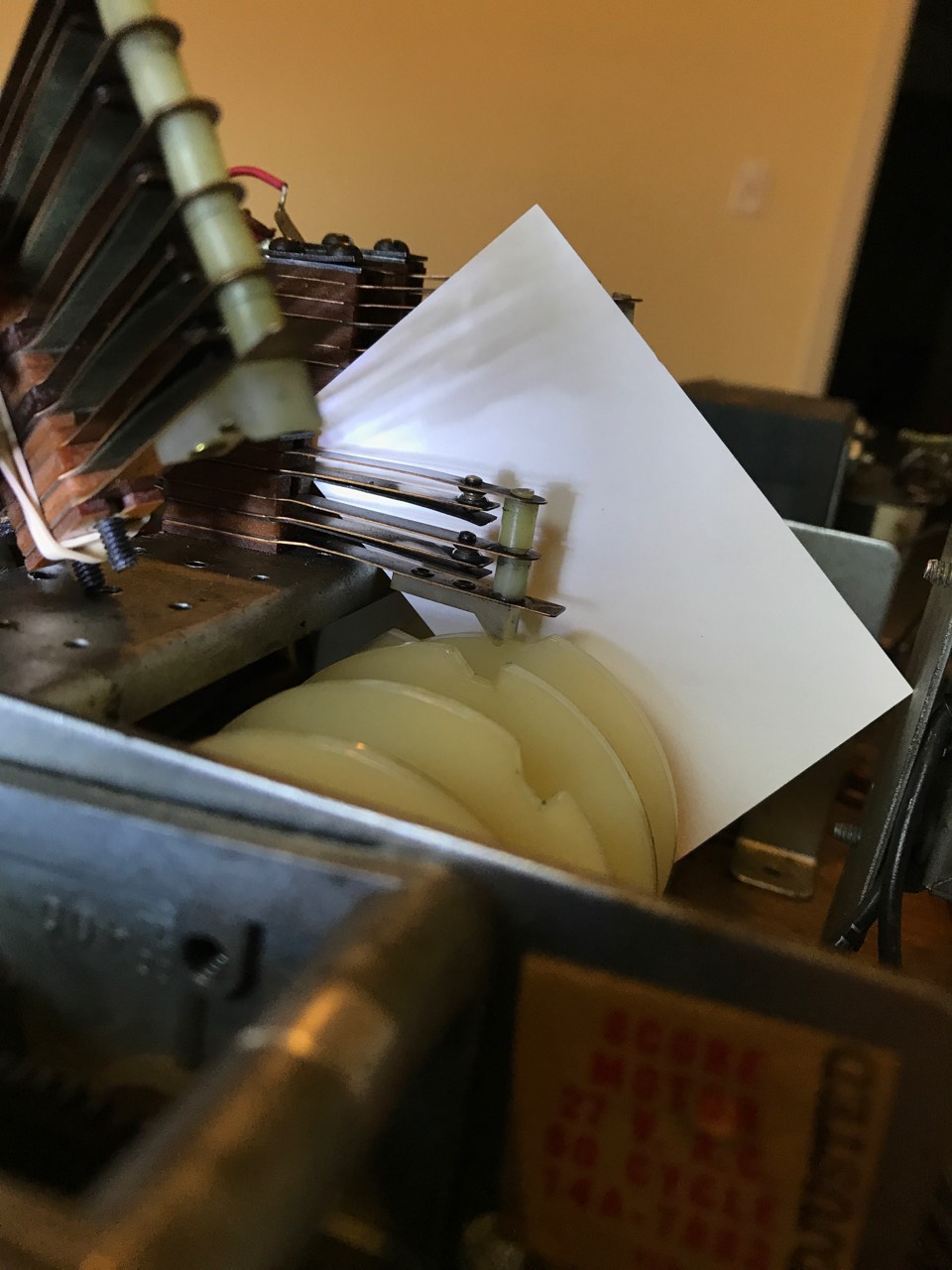
This photo shows the two screws holding the switch stack in place. Loosen the screws until the switch stack comes free. We then wrap a rubber band around the screws on the switch stack to hold it together.
Cleaning of the Switches

With the first switch stack out of the motor and wrapped in a rubber band, it is relatively easy to access each switch and clean the contacts. Our favorite technique is to use the Dremel and the 1/8″ Carbon Steel Brush 443. Each switch contact should be nice and bright. Follow up with 91% alcohol and a q-tip to remove any leftover residue.
If following this procedure, the first stacks to work with are the two left over in the center. It is possible to remove one of those stacks to clean the contacts (wrap the stack with the rubber band!), then replace it for adjustment.
Adjusting the Switches
Note that these are switches from a Williams score motor, but the same principal applies.


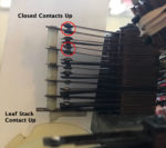


After the contacts are cleaned, note how the score motor moves and the switch stack moves. In this photo, the switch stack is ‘up’ most of the time, then moves ‘down’ into the notches. In this example, the switches open up at the top, them make contact when they are ‘down’.
Caution: Manually move the score motor in the correct direction. The stacks always climb up a gentle rise, then drop off a ‘cliff’. Moving in the wrong direction may destroy the switch and / or the motor.

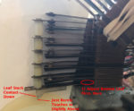
1) Using the switch adjusting tool and the proper technique, adjust the bottom leaf so that the leaf stack contact just barely touches the wheel or is slightly above the wheel at the low spot on the wheel. We do not want much pressure on the wheel, otherwise parts will wear faster.
 2) Next, adjust the bottom most moving leaf so that the spacer touches the bottom leaf. It should not push the bottom leaf down very much, but it must touch.
The force of this leaf down will push the leaf stack contact down just a little.

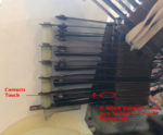
3) Finally, adjust the shorter stationary blade up so that the two contacts meet and make firm electrical contact. This leaf must make contact with the longer moving leaf. But when the stack moves up, these two contacts must separate.

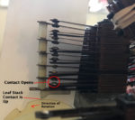
4) Check your adjustments by rotating the wheel in the correct direction. The leaf stack contact will ride along the wheel and push the stack up. Ignore the switches that have not been adjusted and just look at the one you worked on. When the leaf moves up, the two contacts must separate. If they do not, then adjust the shorter stationary leaf back down a little bit so that the two contacts separate.
Repeat steps 2 – 4 for each of the remaining leafs.

Note that some contacts will occur when the stack is up. When adjusting a lower set of leafs, while performing steps 2 – 4, insure that the upper shorter fixed leaf does not make contact when down, but does make contact while up.
Adjusting the remaining switches on the stack can sometimes affect the lower adjustments. After completing all the adjustments, go back and review the stack for proper operation. One may find that an earlier adjustment might need changing.
Also pay attention to the pressure of the Leaf Stack Contact onto the wheel. If the downward pressure of all the leafs is too great, then the parts will wear. It might be necessary to go back and lift up each of the longer leafs just a little.
First time through, this process may seem daunting. Try starting with the smallest switch (least number of leafs) first. Repeat adjusting your first stack. After a couple of time, this will become much easier.
Reassembly
After finishing up with one stack, carefully check its operation to insure that it is working properly.
Then attach the next stack in the order. Repeat the above adjustment process. Continue with each stack until all are cleaned and adjusted.
While the bottom panel is out, we recommend cleaning and adjusting the other relays. Then just reassemble. Enjoy that your score motor will work like the pinball machine is brand new and it likely will not give your problems for years to come.
Comments
Comments, including suggestions, improvements, errors, etc. are welcome (see below).
If you have a specific question about your game that does not directly apply to this page, please see our FAQ section.
External Links
EM Repair the Score Motor – Detailed information from the always excellent PinWiki.
Demystifying the Score Motor – An excellent intro if you don’t get seasick easily.
I appreciate the update to this page. I am in the process of trying to solve a GTB score motor issue on a 1972 Flying Carpet machine that I bought during the Pandemic. My problem appears to be with the switch on motor 2B and/or 4C. The O relay gets stuck on and the ball return keeps kicking nonstop while the score motor keeps spinning. I took the metal apron out and can play the game as long as the ball does not end up in the out hole. I trigger the ball switch to get the game going. Anyways, from what I can tell, that is the only problem with the score motor.
Based on your recommendation, I’m going to clean and check all the motor switches
I have never seen the tip about using rubber bands to keep the stack together. Thank you
Also, is it necessary to replace the fish tape? It looks like the contact heads on a couple of switches on the 4C stack had been replaced by someone else. Based on other repairs I have seen on this machine, I’m not convinced they would have put the fish tape back. The replacement contacts heads look a bit bigger than the original ones, but the switches still appear to make and break correctly. Is the make/break happening electrically, I don’t know.
Editorial: I think you can delete the second sentence here.
*At the bottom of the Leaf Stack is the Switch Dog.
*The Switch Dog on the Scoring Wheel. << Huh?
“Also, is it necessary to replace the fish tape?”
It should not be. Unless the fish tape is badly damaged or missing. It is there to insulate between the switches. If it is missing or damaged, it must be replaced.
Thank you for the edit suggestion. We have the author proof read, then have two more people check and still miss stuff. Groan.
Thank you for this helpful write-up. While you did warn that “it is crucial to hold the switch stack together” when removing it and to avoid removing them individually, you didn’t explain the real reason! In some cases, especially on the switch stack at position 1, there are adjacent switches soldered together (1A and 1B on a Gottlieb Lucky Hand for example) and also in some cases there’s a very thin jumper wire that is soldered from one lug to another on switches that could be further apart. Again, on Lucky Hand there’s one from 1A to 1C.
These can be very tricky to ensure soldering back in the right place if they accidently get broken off when removing!
I think it would enhance your write up to hi-lite this area on these score motor switches!
Thanks.
Thanks Terry!