Reproduced with permission from terryb.
Written by terryb
A. Basic Electronics
B. Transistors
C. Integrated Circuits
D. Test Equipment
E. Operators Manual
F. Reading Schematics
G. Electronics Troublshooting
This is part one of a seven part series intended to provide a basic knowledge of electronics, test equipment, service manuals and troubleshooting in order to allow the reader to effectively repair pinball games. With that goal in mind I have simplified the explanations and purposely glossed over some details that add no value, and can easily confuse beginners.
Voltage, Current and Resistance
The three fundamental properties of electricity are voltage, current and resistance and by measuring these properties we can troubleshoot an electronic circuit.
Voltage (measured in volts) refers to the amount of potential energy in a circuit or component. If we draw an analogy to a waterfall, voltage would represent the height of the waterfall. The higher the waterfall, the more potential energy and therefore the higher voltage reading. It is important to note that since voltage is potential energy, if we built a dam at the top of the waterfall and stopped all water flow, the voltage would still be the same, but our current would change dramatically.
Current (measured in amps or amperes) refers to how much electricity is flowing (how many electrons are moving through a circuit in a unit of time). Going back to our waterfall example, current would represent the flow of water over the falls each second. Anywhere from a dribble to a full-on Niagara Falls.

Resistance (measured in ohms) refers to how much the material that is conducting electricity resists the flow of electrons (conductivity is the opposite of resistance). The higher the resistance, the lower the flow, or amps, and the lower the resistance, the higher the flow, or amps. In our waterfall analogy, suppose we directed the output of the dam through a pipe. A larger pipe would have less resistance and a higher flow rate and a smaller pipe would have more resistance and a lower flow rate.
In case you didn’t realize I just slipped Ohm’s law in on you (more later).
Power
In addition to voltage and current, there is another measure of electron activity in a circuit. It is a measure of how much work can be completed in a given time period. For example, in the case of automobiles, engine power is rated in horsepower and one horsepower is defined as 550 foot-lbs of work per second.
Remember that voltage is the specific work, or potential energy, and current is the rate at which electricity flows through a conductor. Therefore we know the amount of work being done and the time period. By multiplying the two together we can determine power: P (power) = I (current) x E (voltage).
The reason this is important to understand is because in an electronic circuit at least some of the power is dissipated as heat.
For example we have a simple circuit with a battery and a light bulb. The battery is supplying 18 volts and the bulb has a resistance of 3 ohms. Using Ohm’s Law, which we’ll discuss shortly, we can determine the current of the circuit is 6 amps. Therefore the power dissipated by the bulb (a combination of light and heat) is 108 watts (6 amps x 18 volts).
This is why many components have a wattage rating. In the case of resistors all of the power is dissipated as heat so the power rating tells us the resistor’s ability to dissipate heat. As you can probably guess, if the circuit is creating more power than the resistor can dissipate, we end up with a toasty resistor.
Fighting the Current
Sticking with our waterfall analogy, I will frequently refer to upstream or downstream in the troubleshooting guides. When talking about a supply voltage (i.e. – 18 volt lamp supply), moving upstream refers to heading towards the voltage source and downstream means towards the controlled device (solenoid, lamp, etc.). In logic circuits upstream refers to the processor side and downstream refers to the point at which the ground is provided, through a transistor, to the controlled device.
In other words, upstream is towards the wall outlet or the processor (the current source) and downstream is the opposite direction, or towards ground (the final destination of the current flow).
Note: When Benjamin Franklin made his conjecture of charge flow, he actually got it wrong. We have since learned that current flows from negative to positive. In this article series I will use conventional flow notation (from positive to negative) since it is still commonly used and is easier for beginners to deal with.
Ohm’s Law
The relationship between the three fundamental properties of electricity are described using a mathematical principle known as Ohm’s Law. The formula was originally written as E = I * R (voltage equals current times resistance) but is most commonly expressed as I = E / R (current equals voltage divided by resistance). If you remember your high school algebra you will know that both formulas are equivalent.
If we go back to our waterfall analogy this makes sense.
- Pressure == Voltage
- Flow Rate == Current
- Resistance == Resistance
The higher the waterfall the higher the flow rate since there’s more pressure. So the higher the voltage the higher the current (8 volts / 2 ohms = 4 amps versus 16 volts / 2 ohms = 8 amps) and the lower the voltage the lower the current (8 volts / 2 ohms = 4 amps versus 4 volts / 2 ohms = 2 amps).
On the other hand if the output of the dam was limited to a garden hose, the resistance would reduce the flow rate. So the higher the resistance the lower the current (8 volts / 2 ohms = 4 amps versus 8 volts / 4 ohms = 2 amps) and the lower the resistance the higher the current (8 volts / 2 ohms = 4 amps versus 8 volts / 1 ohms = 8 amps).
Although you don’t need to be an expert at Ohm’s Law, unless you’re designing electronic circuits, it is important to have a basic grasp of the relationship between the three elements when troubleshooting.
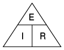 Here’s a little trick for remembering how to solve the equation for any variable (see image to right). If you want to solve for voltage (E) then cross off the E and you’re left with E = I * R. If you want to solve for current (I) then cross off the I and you’re left with I = E / R. If you want to solve for resistance (R) then cross off the R and you’re left with R = E / I.
If you have trouble remembering the sequence on the triangle, here’s a hint: it’s in alphabetical order.
An important caveat to Ohm’s Law is that all measurements (voltage, current, resistance and power) must be measured relative to the same two points in a circuit. We’ll see this in action in a little bit.
Alternating and Direct Current
There are two types of currents: AC (alternating current) and DC (direct current). The main difference between AC and DC is that AC flows in both directions (alternating between the two) while DC flows in one direction. Each has its own advantages and disadvantages and are used in specific applications based on those characteristics.
While the electricity delivered to your home is AC, all the electronic devices in the house convert the AC to DC in order to function.
The conversion from AC to DC is done by a bridge rectifier (covered in Electronics Tutorial Part 2) and every electronic device in your house has one or more of them. Everything before the bridge rectifier in your pinball game is AC and everything after it is DC. Although the conversion form AC to DC is done very soon after the wall plug there are some circuits, like GI lighting, that bypass the bridge rectifier and use AC.
While DC circuits consist of a high line (5 volts for example) and a low line (ground), AC circuits can have either two or three wire configurations. In a two-prong setup (like a lamp for example) the two lines are hot and neutral. In a three-prong setup (a refrigerator for example) the third line is ground. Unlike a DC circuit where ground is an integral part of the circuit, in an AC circuit ground serves no purpose other than safety.
When measuring a DC voltage with a DMM the red lead is placed on the high line and the black lead on ground. In the case of AC the leads are placed across hot and neutral and which goes where doesn’t matter. For example, with GI lighting the leads are placed on each side of the bulb (one side is hot and the other side is neutral).
Serial and Parallel Circuits
 Electronic circuits can be either serial, parallel or a combination of the two (the latter being the most common). This distinction is important because the type of circuit affects the readings you will get when troubleshooting.
In the image to the right you can see the three types of circuits. In a serial circuit there is only one path for current to flow whereas in a parallel or serial-parallel circuit there are multiple paths (called branches).
For now we’ll stick with resistors in the examples, but the circuit could include any type of component (and all components have some resistance). We’ll also assume the resistors are all 100 ohm.
If we test across any resistor in the serial circuit we’ll read 100 ohms since the current has no alternate paths to follow. To calculate the resistance of the entire circuit (hint, 300 ohms) we can use the following formula: R = (R1 + R2 + R3…).
The current flow will be the same across all resistors. In our example, the voltage drop will also be the same across all resistors, but if the resistors are of different values the voltage drop across each will vary. Using Ohm’s Law we could calculate the voltage drop in a serial circuit by testing across each resistor.
This gets a little trickier in a parallel circuit since the current has multiple paths, all of which it will use. If we measure across any of the resistors we will get a reading of 33.33. ohms because we’re reading across all of them, whether we want to or not. This can be calculated by using the formula: R = 1 / (1/R1 + 1/R2 + 1/R3…).
Although each branch will have the same voltage drop, there will be a different current flow across each resistor. Using Ohm’s Law we could calculate the current flow across each resistor in a parallel circuit.
Although I won’t cover it here, Ohm’s Law can be used to analyze complex (serial-parallel) circuits by breaking them down into serial and parallel pieces.
A good example of a serial circuit in a pinball game is the controlled lamp circuit. Voltage is supplied on one side, flows through a diode, through the bulb, through a switch and to ground. Since this is a serial circuit we can test the diode while it’s in circuit. Another example of a serial circuit is a fuse, which can also be tested while in circuit.
A solenoid with a diode across it is an example of a parallel circuit. In this case we can’t test the diode while it’s in the circuit because we will be reading the resistance of both the coil and the diode. Instead one leg of the diode has to be desoldered before testing.
Circuit Symbols
Image 2 provides a list of the most common circuit symbols.
Circuit Boards
 Most circuit boards since 1980 use through-hole technology. This allows traces to be located on both sides of the board and when conductivity is needed from one side of the board to the other a through-hole is used (see image to the right). When a connection to a component is only needed on one side of the board, a pad is used rather than a through-hole.
The through-hole, or pad, is actually one physical part and the board trace a second physical part. They are electrically connected once the board is wave-soldered. It is not uncommon for the connection to break right at the point where the through-hole, or pad, is soldered to the board trace. It is also not uncommon (especially after someone has hacked the board) to find the metal liner in the through-hole destroyed .
[Editors note: Through hole ICs are frequently referred to as DIP (dual in-line package). Most are becoming difficult to find.
In the last few decades, a new technology has replaced most ‘through hole’ circuit boards. It is called ‘surface mount’ or SMD (surface mounted devices) for short. The components are referred to as SOT, SOP, etc. These circuit boards use much smaller components and are difficult if not impossible for the home hobbyists to repair. When these boards break, they are usually sent back to the factory for repair or replacement.
Fewer and fewer through hole components are being manufactured, making it more difficult for people to keep these old pinball circuit boards repaired.]
Resistors
 While resistance is usually a by-product of a circuit (a bulb, or even a trace on a board, have resistance) in the case of resistors the engineer is purposefully adding resistance to a circuit in order to affect current or voltage (remember Ohm’s law).
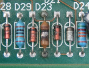
Resistors are rated in ohm’s (the higher the number the more resistance), tolerance (allowable variance from the rated resistance value) and wattage (power). The colored bands on the resistor are used to provide this information (see Image 1).
The wattage rating is a measure of the resistor’s ability to dissipate the heat energy created by current flowing through it. The power rating of any resistor is roughly proportional to its physical size.
Resistors do not have any polarity and can be installed either way in a circuit. When replacing resistors you should exactly match the resistance and tolerance ratings (although you could go to a tighter tolerance, the resistor will cost more). While you can go with a higher wattage rating, it is best to use the same rating in order to maintain the form factor.
In a circuit, resistors are commonly used to drop voltages. If we go back to our waterfall analogy, let’s add a pipe that runs half way down from the dam to a ledge. At that point another pipe runs from the ledge to the bottom of the falls. If both pipes are the same size (same resistance) and the potential (voltage) at the dam is 12 volts, the potential at the ledge will be 6 volts.
This is the same theory behind potentiometers (the volume knob on an old-style radio) except the ledge is raised up and down making one pipe shorter and the other longer. As the ridge goes up the voltage goes up and as the ridge goes down the voltage goes down.
The other common application is as a pull-up or pull-down resistor. Pull-up resistors raise the output of a logic device to the desired level (for example, 5 volts). Pull-down resistors lower the logic level to the desired level (0 volts).
The circuit shown above uses a 5 volt logic level input to actuate a 12 volt relay. When the input is high (5 volts) the solenoid is energized and the resistor does nothing. When the input is low, pull-down resistor R1 ensures that the input is pulled down to a logic low (0 volts).
The 7404 buffer simply outputs whatever it receives as input so when the input is 5 volts the pull-up resistor R2 raises the output from 5 volts to 12 volts. When the input is low the resistor does nothing. Finally 12 volts turns on the N-channel FET (transistor) which turns on the relay.
Don’t be overly concerned with the buffer and transistor, we’ll cover them in further tutorials.
Resistor Network
 One unique type of resistor packaging used in pinball games is the resistor network. A resistor network consists of a group of resistors in a single package, which can be bussed or isolated (see image to right).
In the case of an isolated resistor network, there will be an even number of leads and both leads on each resistor will be connected to the board. Bussed resistor networks will have an odd number of leads with one lead of each resistor going to pin 1 and the other having its own connection to the board.
Bussed resistor networks will have a dot on the package indicating pin 1 and typically a square on the circuit board for pin 1. On isolated networks it does not matter which way they are installed.
Testing Resistors
 To test a resistor set your DMM to ohms and measure across it. Keep in mind that every component provides at least some resistance so the only way to test a resistor in a parallel or serial-parallel circuit is to unsolder one leg.
The good news is that most resistor failures in a pinball machine will be a result of overheating, and won’t require a DMM to identify (see brown resistor in middle of image to the right). While this example is an extreme case, other visual indications include fading of the resistor’s color code, blackening of the circuit board below the resistor or blistering on the resistor.
You can also use your finger to feel blistering or bubbling.
Capacitors
Capacitors are electronic devices that store energy in an electric field. Think of them like short term batteries. The amount they store is based on their value which is rated in farad’s. They also have a tolerance rating which is typically printed on the component. The letters J, K or M indicate ±5%, ±10% and ±20% respectively.
Some capacitors will be labeled with three digits and a letter. The third digit is the multiplier, and as explained above the letter is the tolerance. For example, a capacitor labeled with 103K is .01uf (add 3 zeros to 10 to get 10000pf and then divide by 1,000,000 to get uf).
The voltage rating on a capacitor is the maximum amount of voltage that it can safely be exposed to and store. When replacing capacitors it is best to match all of the ratings, but you can go with a higher voltage rating if necessary.
Capacitors are often used to smooth the output of power supplies (the supply voltage charges the capacitor and if the voltage drops the capacitor discharges, raising the supply voltage). They are also used in resonant circuits that provide a specific frequency (think of an electronic version of a tuning fork–you hit it and it vibrates at a certain frequency).
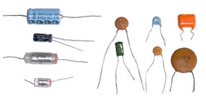 While standard capacitors are non-polarized, electrolytic capacitors have a positive and negative side and must be installed that way. Polarized capacitors will often have a marking (+ or -) on the case indicating either the negative or positive lead. Sometimes the negative lead is marked with a black line rather than a symbol.
The circuit board will typically be printed with a symbol (+ or -) to denote the positive or negative lead. Most schematics will also put a + or – sign by the capacitor symbol to show orientation. If there is no symbol, just a flat line and a curved line with a space in-between (see Image 2), the flat line is positive.
Physically capacitors come in three versions: radial, wafer and axial. Radial capacitors look like a small beer can with both leads on one end. Wafer capacitors also have both leads on one side, but are flat. Axial capacitors look like radial, but with one lead on each end.
Testing Capacitors
Capacitors cannot be tested in circuit (one leg must be desoldered) and to be accurately tested must be under load which requires an ESR meter, which costs over $100. Some multimeters have a capacitance test, which is not as accurate but will sometimes do the job. Although it sounds odd, the smaller the capacitor the more likely you will get an accurate assessment. The capacitor must test at or slightly higher (10 – 20%) than its rated value to be considered good.
Inductors and Chokes
Inductors and chokes are similar to capacitors, but store energy in a magnetic field. Inductors are used to filter out certain frequencies and are valued in Henries. The only way to accurately test an inductor is out of circuit with an ESR meter. A very basic test, which does not prove the inductor is good, only if it’s bad, is to check it with an ohmmeter. You should get a reading very close to zero.
Fuses
A fuse in an electronics circuit consists of a glass enclosed metal wire or strip which is intended to melt when excessive current flows through it. By melting, and thereby opening the electrical circuit, the fuse serves as a sacrificial lamb to prevent damage to other components. Although in reality, many times the fuse will blow after other components have been destroyed. Blown fuses are the result of a short circuit, failed component or excessive current draw (overload).
There are two main types of fuses: standard and time-delayed (also called slo-blo or slow blow). Fuses are rated in amps (labeled on the metal end-cap of the fuse) and in the case of a standard fuse will blow instantaneously once its rating is exceeded (at least theoretically). A slo-blo fuse will allow the current draw to exceed its rating for a moderate period of time before it blows.
The two types of fuses are not interchangeable. A standard 5 amp fuse used in place of a 5 amp time-delayed can blow even when there are no circuit problems. On the other hand, using a slo-blo in place of a standard fuse risks damaging components before the fuse blows.
You can verify the condition of a fuse using an ohmmeter. A good fuse should read zero ohms or beep when your meter is set on continuity. A fuse can look good and still be open so don’t rely on a visual inspection. Fuses do not have to be removed for testing.
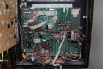
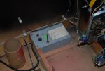
Most of the fuses in a pinball game are located in the backbox (see Image 3). In some cases fuses will be mounted directly on the backbox (see Image 4) rather than on the boards. The AC line will also have a fuse (see Image 5) and some games will have fuses mounted under the playfield for magnets and other special items.
It is important to note that it is not at all uncommon to find incorrect value fuses installed. Therefore you first step should always be to verify the fuses rating versus the label(s) inside the backbox or in the service manual.
[Editors note: More on testing fuses.]
There are three categories of fuses in a pinball game: main power fuse (mounted in the metal box in the lower cabinet), power supply fuses (5 volts, 12 volts, etc.) and circuit fuses (a section of GI lighting, for example). For more info see article on Troubleshooting Blown Fuses.
Coils/Solenoids
Solenoids are made from a long, thin loop of wire, often wrapped around a metallic core, which produces a magnetic field when an electric current is passed through it. Their rating is determined by the size of the wire and the number of loops.
In order to test a solenoid set your DMM to ohms and then place the test leads across the coil (polarity doesn’t matter). Most coils will read between 2 and 12 ohms. Flipper coils will have a higher resistance reading (sometimes as high as 160 ohms) and have two windings rather than one. This article provides the exact resistance readings for each type of coil. Of course, you could always just compare two coils of the same type.
References
- The following is a great site that provides more in-depth electronic tutorials: All About Circuits.
- Worksheets from All About Circuits – a great way to reinforce what is covered here.
- Randy Fromm’s YouTube Channel also has some great videos on basic electronics theory.
Comments
Comments, including general questions about electronics troubleshooting, suggestions, improvements, errors, etc. are welcome (see below).
If you have a specific question about your game, please see our FAQ section.
When I turn on the machine the GI lights all light up went I try to start a game it blows a fuse. What do you need to know so can check on the problem. Thank you. Yes I need help as am a newbe trying to get the Black Knight going. Thank you again.
Thanks for visiting our website. As a newbie, you are going to need to have experience with electronics as well as equipment such as a voltmeter and perhaps a digital logic probe in order to fix this. Also keep in mind that some very high and dangerous voltages are present such as those required to run the displays.
If you are a complete newbie, you should get someone who knows how this all works to help you out.
Since the fuse blows when you start a game, it could be a locked on or defective coil. The first thing we always recommend is to check the voltages. In this case, since the game boots, it maybe that a coil is locked on. We suggest that you start here:
https://homepinballrepair.com/troubleshooting-the-williams-and-data-east-soleniods/
https://homepinballrepair.com/troubleshooting-the-williams-and-data-east-computer-controlled-solenoids/