Flipper Repair Introduction
1) How a Flipper Works
a) Flippers in Detail
b) Serial Coils
c) Parallel Coils
d) Solid State Flippers
2) Flipper Components
3) Parts Listing
4) Two Different Types
B. Solid State Flippers Intro
C. When to Rebuild
1) Troubleshooting
2) Mechanical
3) Electrical
4) Diodes
D. Rebuilding
1) Tools Needed
2) Newer Flippers
E. How To
1) Steps Involved
2) Install EOS Switch
3) Install Capacitors
4) Flipper Bat
5) Adjust EOS Switch
F. Upgrade To The Best Flippers
G. How Solid State Flippers Work
1) Fliptronics
2) DE/Sega
3) Sega/Stern Whitestar
H. External Links
Note: This is a general overview for all flippers. A specific version has been written for Williams and Williams/Bally Fliptronics flippers.
Of the machinery in a pinball machine, the flippers may get the most use and therefore wear and tear. Therefore, the flippers may need more maintenance than any other part of a pinball machine.
Cautions: Must read before proceeding. Machine must be turned off and unplugged.
A glossary of terms used on this page.
Portions of this article was originally posted on PinballRehab.com.
Reproduced with permission from terryb.
Note: Click on any image or links for a larger image.
Skip all of the important information and jump to rebuilding.
How a Flipper Works
In order to diagnose a flipper problem, it is important to understand how a flipper works. This includes serial, parallel and computer controlled flippers. A simplified version is:
1) Player presses a button that closes a switch to complete the circuit
2) The high power portion of the coil is energized
3) The coil creates a magnetic field, drawing the plunger into the coil, hitting the coil stop
4) The flipper opens, opening the EOS switch (most designs)
5) The EOS switch inserts the lower power coil into the circuit (serial) or removes the high power coil (parallel), reducing the power and current draw
6) When the player lets go of the flipper switch, the spring retracts the flipper, removing the plunger from the coil
7) The loss of power changes the coil into a power generator. The collapsing magnetic field creates electricity. For SS (solid state) machines, a diode shorts out this power, preventing damage to the circuitry.
Note: EM pinball machines that have DC solenoids also have diodes on the coil.
Flipper Components
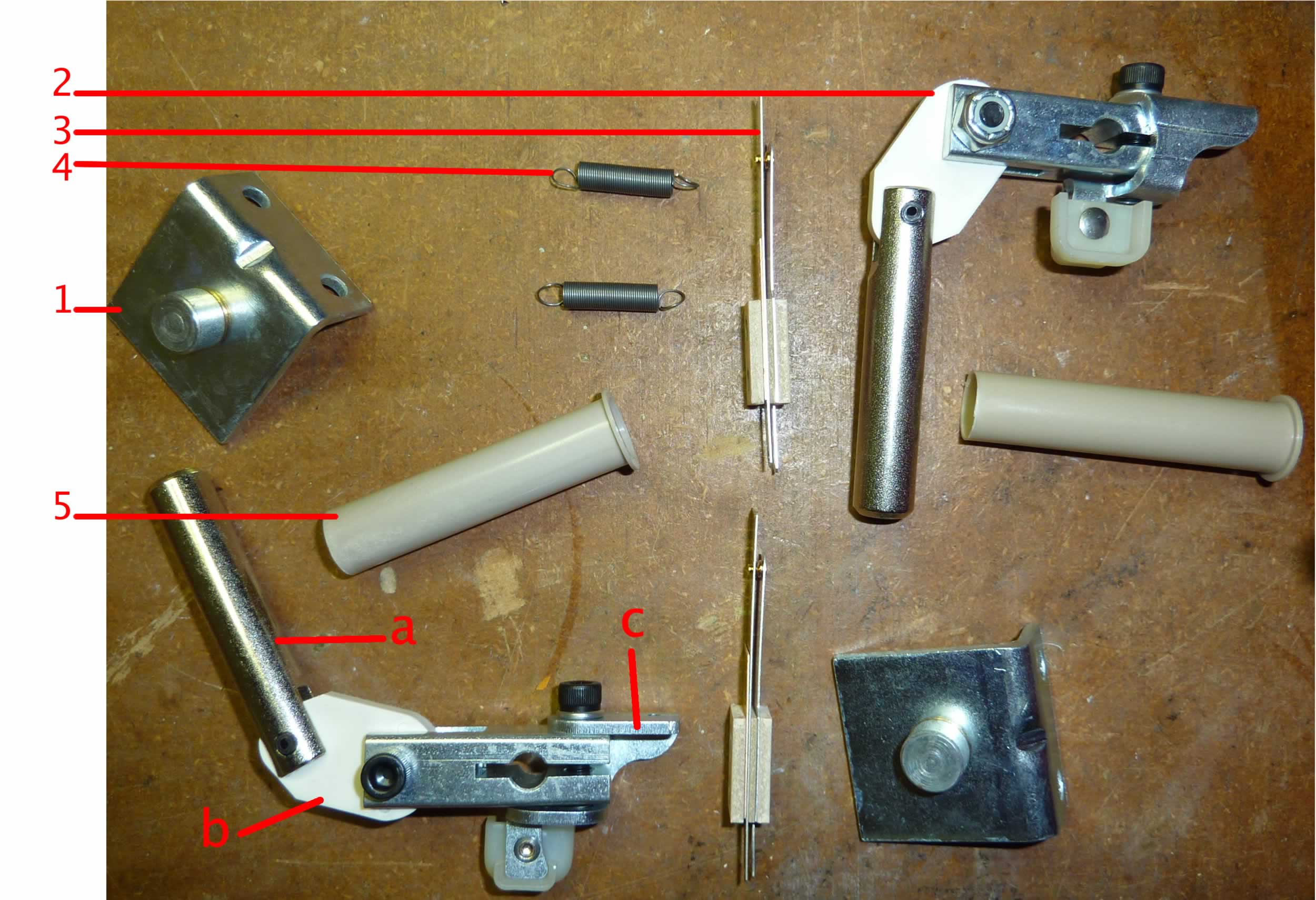
Flipper Parts – Contained in a Typical Kit from a parts supplier.
1) Coil Stop
2) Crank Assembly
– a – Plunger
– b – Link
– c – Crank Arm
3) EOS Switch
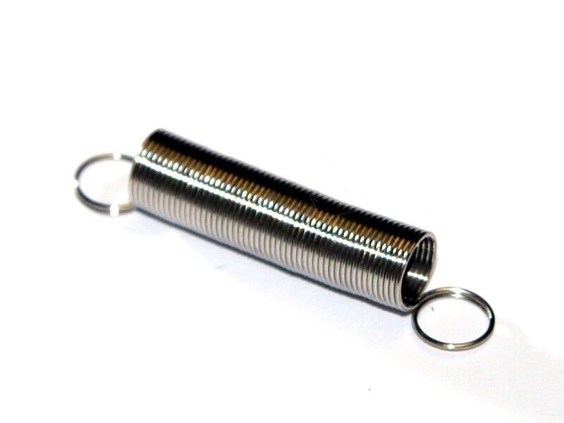
4) Spring
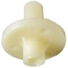
5) Coil sleeve
Upper flipper or lane change switch (some machines – not shown).
* – Flipper Playfield Bushing.
** – New flipper bats (optional – if old ones are damaged or yellowed)
Most flipper coils come with the diodes. Fliptronics 2 games do not have diodes on the coil.


*Optional (usually not included in the kit) – the bushing.
**New flipper bats are required if updating to WPC style.
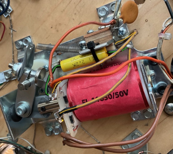
Capacitors
We recommend adding capacitors to the EOS switch and cabinet flipper switches, even if the original design did not have them. Capacitors reduce the size of the spark so the switches last longer. And in early Bally / Stern game, those caps also reduce the frequency of the ‘false activation’ of the solenoids where they fire even when the pinball does not touch the switch. This is especially true with the pop bumpers.
Supplies Needed
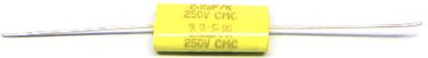
1) 2.2uF 250v Axial Capacitor for the EOS switch. Pinball Life and Marco.
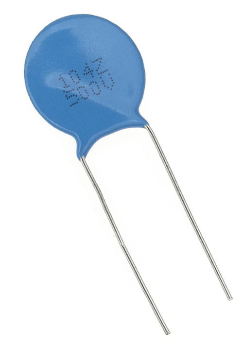
2) Ceramic Disc Capacitor – 0.1uF 500V. Pinball Life and Marco.
3) Shrink tubing (thin or fine wire sized) – optional
4) Zip tie.
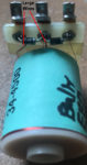
The 2.2uF cap is installed on the EOS switch bracket. It is held in place with a zip tie. We add thin shrink tubing to the wire connections for insulating purposes.
The disc capacitor is added to the cabinet switches. On Bally / Stern games with upper flipper(s), these have a second switch on the EOS switch. That acts like a cabinet switch. We add the 0.1uF cap to that also.
An extensive list of game / manufacturer specific parts are on this page.
Included is a description of different coil stops and sleeves.
Three Different Types


Pinball flippers worked the same way from the dawn of flipper pinball until the 1990’s. Prior to this change, full power went through every flipper switch and those switches burned out quickly which led to weak flippers.
For more information about different types of flippers, see how flippers work.
In the mid-80’s, games started to be converted from serial coils & wiring, to parallel coils & wiring.
About 1990, Data East / Sega (which became Stern), converted to computer controlled solid state flippers. Bally / Williams introduced Fliptronics about 1992 which also used low voltage and computer control. Sometimes, both these systems are referred to as Fliptronics, but that is a Bally / Williams term. The big difference between these two systems is the way we deal with their switches. The rest is the same.
For more information, see the page on Sold State Flippers – Fliptronics vs. DE/Sega/Stern.
When Should I Rebuild A Flipper?

Signs that a flipper rebuild is due are:
* They are sluggish or lack power.
* A flipper sticks and stays in that position when the power is turned off.
* When open, one moves further than the other (sometimes wrong coil stop was installed on one flipper).
* They are not aligned when at rest (this is usually a simple adjustment).
* You just purchased a used pinball machine and the previous owner cannot tell you when they were last rebuilt.
As flippers wear out, they lose power slowly. As a regular user, it is difficult to notice a gradual loss of power.
What wears out is the linkage in the crank assembly, where the parts rotate. The holes should be round. With time, they become oval. That means, as the plunger comes into the coil, there is an extra distance that the plunger has to travel until the flipper rotates and that saps power.

Other components that can reduce power to the flippers are the flipper button switch and the EOS Switch. For games prior to (about) 1992, the full power has to go through these switches, so any wear and tear on those two switches can sap the power. The easiest thing to do is replace those switches. EOS switches come with flipper rebuild kits.
Flipper button switches are not included in kits and must be ordered separately. It maybe possible to file those switches to restore their effectiveness, but this requires a certain technique – many people destroy these switches than fix them by filing them. Filing or replacing these contacts are as important as the EOS switches.
Check to insure that the correct coil is installed (see your manual). Some previous owner may have just thrown in a coil they had handy. Too weak of a coil, and it will act like it needs a rebuild. Too strong and plastics may be broken.
Troubleshooting Flipper Issues
When a machine starts to have weak flippers, owners are quick to blame electrical problems. By far, the greatest cause of weak flippers are physical problems than can be easily diagnosed by those mechanically inclined.
Note: Never lubricate any flipper parts.
Mechanical Checks:
1) Turn the machine off and unplug.
2) Remove the playfield glass. Remove the pinball(s). Tilt the playfield up and lean it against the backbox. Be certain the playfield is secure and will not come crashing down.
3) Manually move the flipper back and forth. Listen for any rubbing. Be certain that the flipper does not rub the playfield. Pull up on the flipper. There should be a small amount of up / down movement.
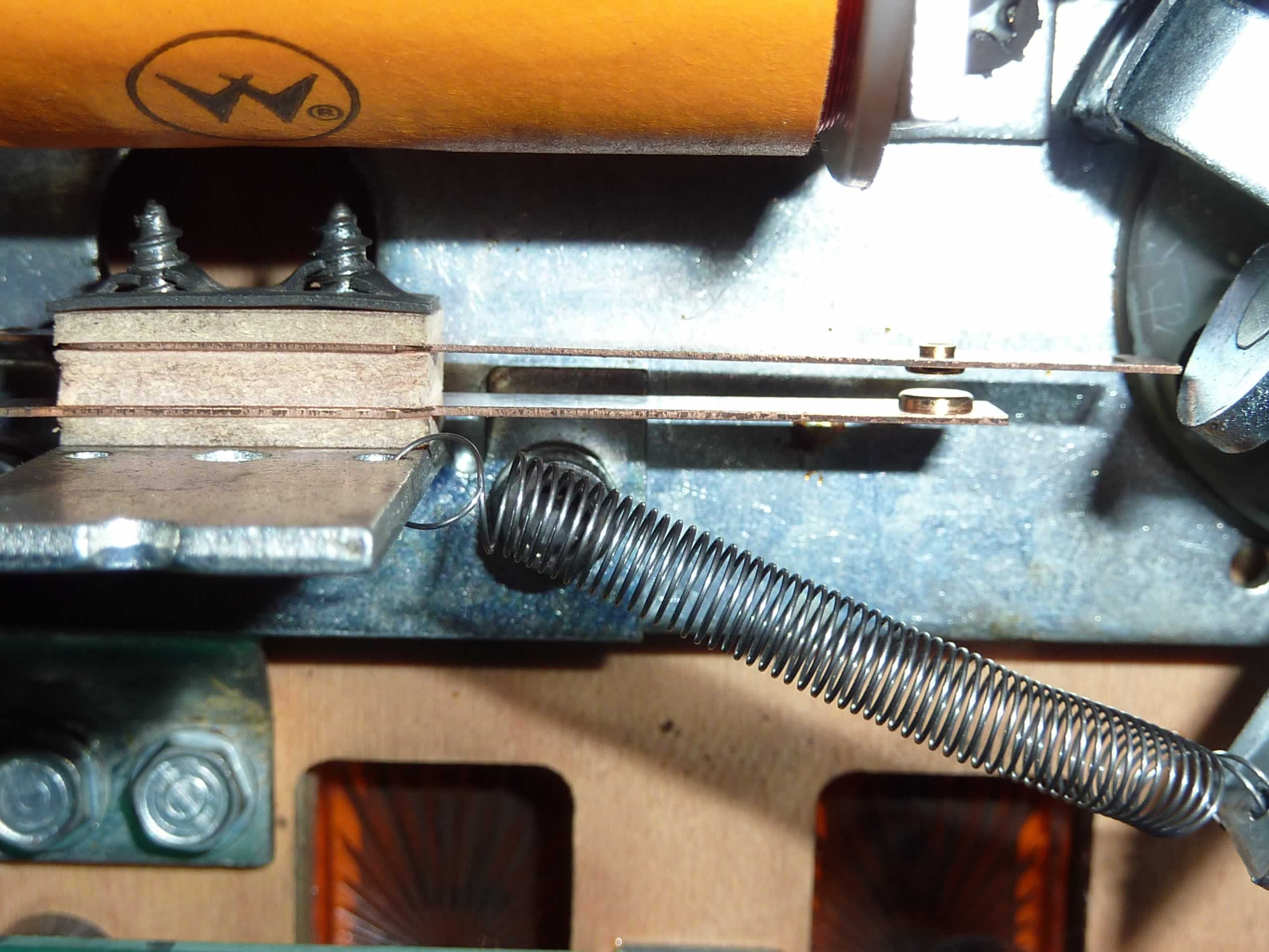
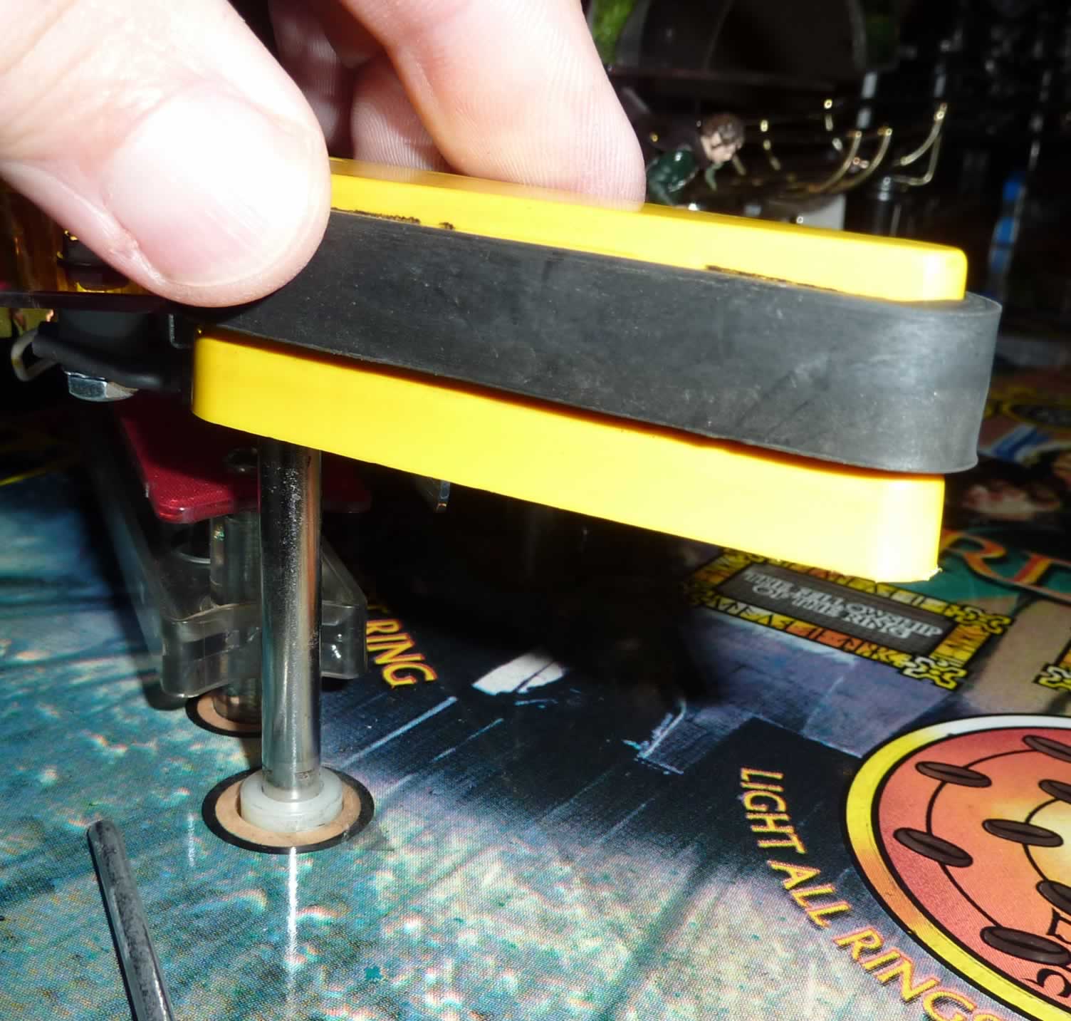
4) Check for a broken or weak spring.
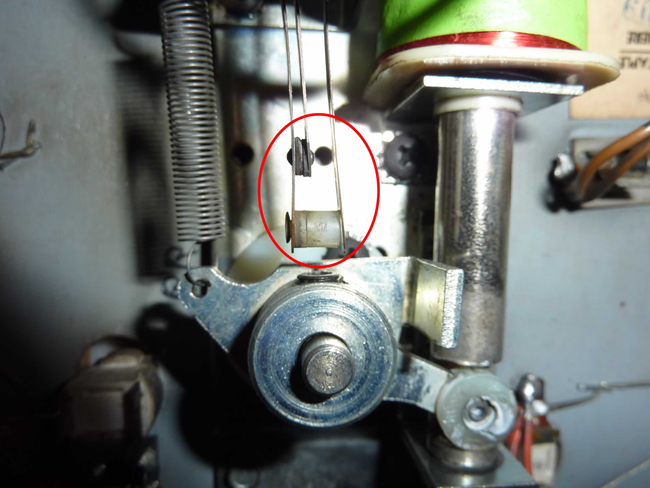
5) Check for wear on the Crank Assembly Link (see photo above). This is what usually wears out first. If the hole in the link has become elongated, replace the Crank Assembly or purchase a rebuild kit.
6) Plunger and/or coil stop become mushroomed. This can cause the flipper to stick open or not move freely.
7) If there is any doubt about the wear and tear of components including the Crank Assembly, springs, EOS switch, or Coil Stop, purchase and install a rebuild kit.
8) Inspect the EOS switch and flipper switch for pitting and wear.
Electrical Problems:
Read and understand “how a flipper works“. A great deal of current flows through the flipper coil when it is first pressed and any electrical resistance will slow it down. If working on Fliptronics or DE/Sega/Stern computer controlled solid state flippers, read this page.
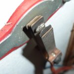
Understand what type of flipper system you have. Generally, games older than ~1992 have the full power going through the flipper EOS Switch and Flipper Switch. Those get worn and require filing or replacement. Computer controlled solid state flippers have low power going through those switches and they wear slowly and must never be filed – see photos at the beginning of this page for an example contacts that must never be filed.

1) Turn the power off. This procedure is to test the coil wires for shorts or breaks.
* Insert a piece of paper between the EOS Switch contacts. If this is a Fliptronics flipper and the EOS Switch contacts are open, skip this step.
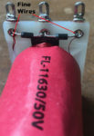
* Identify the tabs on the coil where fine wires come in. That is the hold coil. Set the DVM to resistance and the lowest setting.
* Measure the resistance across these two tabs. The value should be somewhere between 100 – 400 ohms.
* Compare all the flipper coils. If they are significantly different, then one coil might be damaged. A low value could be a partial short. An extremely high value indicates a broken wire.
* Identify the two tabs where the thicker wires are connected. This is the power coil. Measure the resistance. The value should be very low, perhaps between 3 – 10 ohms. Some coils for low voltage systems might read as low as 1 ohm. See coil resistance chart.
* Compare all the flipper coils. If they are significantly different, then one coil might be damaged. A low value could be a partial short. An extremely high value indicates a broken wire. Different coil numbers will give slightly different values.
Note that coils usually do not have to be replaced. When they do, it is because the flipper does not work at all. Sometimes coils get overheated and fail. This is usually caused by a EOS switch that does not open when the flipper ‘flips’. Or a shorted transistor.
A weak flipper is rarely caused by a bad coil.
2) Touch the two leads of your DVM together. It should read nearly zero. This value is your zero value. Connect the leads across the EOS switch. It should read nearly zero. If not, file (older games only) or clean with isopropyl alcohol. If still above (nearly) zero, replace it.
For newer solid state computer controlled flipper machines, this value does not have to be near zero. For Fliptronics machines, the EOS Switch is open. Manually move the flipper until the switch contacts close to insure that the switch makes contact.
If the EOS Switch is not working in Fliptronics machine, an error usually shows when the machine is started.
The following tests 3) & 4) are quite tricky, involve higher voltages and can cause damage if not properly completed. For qualified personnel only:
3) Jumper the EOS switch with heavy duty clip leads. Turn on the pin. Touch and immediately let go of the flipper switch. See if the flipper is stronger. Be careful not to hold the flipper button in since this jumper disables the EOS switch, sending full power through the coil. Holding the flipper switch in could cause a coil melt or a fuse to blow. Just a quick tap. If the flipper is stronger, the EOS switch is defective. Can try cleaning the switch with alcohol or file. Most likely replace.
If no change, then the EOS switch is good.
Remove the jumper on the EOS switch.
4) Lift up the playfield. Take a clip lead and connect it to one side of the flipper switch. Quickly touch across the flipper switch and immediately remove. Does the flipper seem stronger? If yes, file your flipper switch or replace it. If no, then it is not your flipper switch.
Note that doing this can cause quite an arc and scar the clip lead connector.
5) Visually inspect where the wires are soldered to the coil. It is not unusual to see many of the wire strands broken off. The more that are broken off, the higher the resistance which will reduce flipper power.
6) It could be the power supply to the flipper. Check for burnt connectors where the flipper circuit plugs into the power supply board or bad soldering. This is the least likely cause of weak flippers.
Flipper Diodes
A diode conducts electricity in one direction only. It is there to protect the sensitive electronics in solid state (SS) pinball machines.
Why diodes? When DC flipper coils are activated, electricity runs through the coil. When the flipper is turned off, the magnetic field around the coil collapses and the coil turns into an electric generator and power runs in the opposite direction. The power generated by the coil can fry the electronic controls. The diodes conduct electricity one way and short out the collapsing field. Without those diodes, the circuit board will fail. If the coil is installed with the wires switched, those same diodes will conduct when the power is applied to the coil which should blow the fuse.
Electrical Mechanical (EM) flipper coils do not have diodes because they run on AC. The EXCEPTION is those later EM machines that run on DC (Ex: Captain Fantastic). DC machines have a bridge rectifier that converts the AC to DC. Without those diodes, that rectifier will fail.
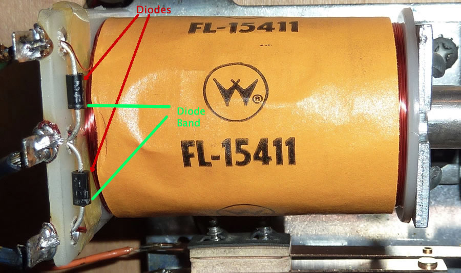
When rebuilding the flippers, take the time to inspect the diodes. Put a little bit of stress on each one with a screwdriver. If they break apart, replace the diode. The diode marking must be in the same direction as the orginal diode (see photo below).
If replacing a coil, be sure to check the diodes on the coil to see if they are ‘pointing’ in the same direction. If they are, connect the wires to the new one in the same order. If the direction of the diodes are reversed, then reverse the wires.
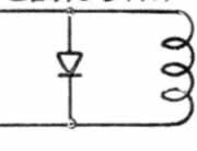
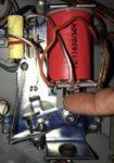
The drawing above shows the symbols of a coil and a diode. A flipper coil would have two coils and two diodes. To the right is a flipper coil with its two diodes. Looking closely at the picture (click for larger photo) shows the bands on the bottom of each coil indicating direction of the diodes.

Note that most new coils come with a 1N4004 diode installed which is good to 400V. If replacing a broken diode, or installing a diode when one is missing, it is a good idea to install a 1N4007. It is rated for 1000V and costs almost exactly the same. Save those 1N4004 diodes for the switch and lamp matrix.
When replacing a diode, it is a good idea to remove the old one. Be certain to pull those diodes tight against the plastic body of the coil assembly. ‘Hanging in the air’ diodes are more likely to break.
Some games have the diode installed on the circuit boards in the backbox. That was done to reduce the breaking of diodes by the physical action of the solenoid, and because too many repair people were installing diodes backwards. Check your game to see if the diode belongs on the coil. Generally, if the old coil had a diode, the new one should also.
Newer games flipped the solder tab / diode side away from the coil stop. This is to reduce the likelihood of the diode leads breaking. If possible, it is a good idea to flip the coil around with the solder tabs and diodes away from the coil stop.
Rebuilding the Flippers
The easiest way to rebuild a flipper is to order a flipper repair kit from a pinball parts supplier.
For a list of parts used in various flipper mechanisms, check out our webpage on Flipper Components as well as your pinball machine manual.

Note that most flipper repair kits do not include the bushings. It is generally not necessary to replace the bushings unless they are worn or damaged. Check the condition of the bushings prior to ordering.
Also, some flipper systems include more than one switch on the flipper. All kits include an EOS switch (end of stroke) which is NC (normally closed – closed at rest). But if there is a second switch, it will be NO (normally open). This switch either activates an upper flipper (early Bally or Stern SS), or a lane change (early Williams). Check your manual and machine to see if that switch is there and be certain to order it.
A Williams lane change switch is #SW-1A-15. Other options include these switches.
Bally / Williams / Stern upper flipper switch can use this switch. The original part numbers are: #ASW-A10-45 (Bally) / #SW-481 (Stern) (or a combo switch), #SW-1010A-12 / SW-1010B (Williams).
Tools Needed


1) Screwdriver (Phillips and occasionally slotted)
2) Allen Wrenches (some flippers)
3) Needle Nose Pliers
4) Wire Cutters
5) Soldering Iron & Solder
6) Nut Drivers and/or socket wrenches
7) Thin metal file and/or flexstone (optional)
Optional:
Flipper gauge – Nice to have, especially when doing this the first time. But making sure of a small amount of vertical movement is usually sufficient.
Shrink Tubing (or similar) – To insulate the (optional) EOS switch capacitor leads and the ends of lane change switches.
Wire stripper (or similar) – This is our favorite model.
Wire – Nice to have a supply of different color stranded wire around. For flippers, #18 gauge is preferred.
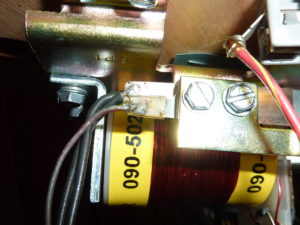
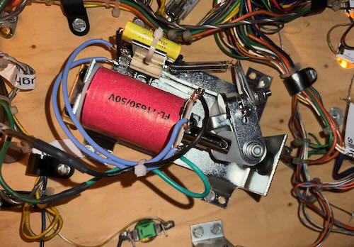
1992 And Newer Flippers EOS Switch Cleaning
Williams/Bally and DE/Sega/Stern adopted computer controlled solid state flippers in the early 1990’s.
Newer Bally / Williams machines have EOS switches that are normally open, then close when the flipper is activated. These switches carry low power and should never be filed. These are either gold or silver plated.
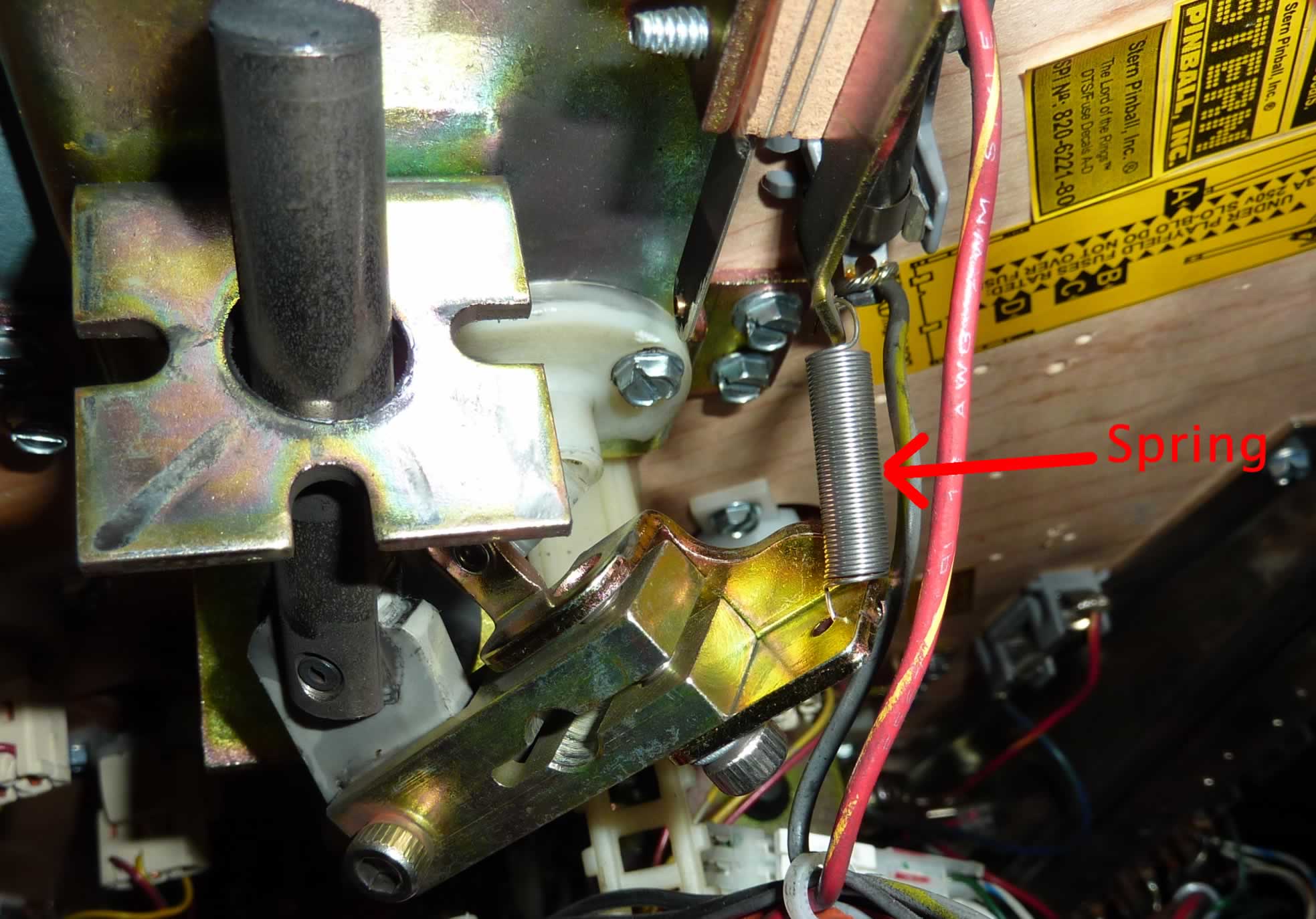
Some other EOS switches on newer machines (like Sega/DE/Stern) are normally closed, then open when the flipper is activated. These are also gold or silver plated and should never be filed. The EOS switches can be cleaned by inserting a business card and dragging it across the contacts as they are held closed by your fingers. Or they can be cleaned with Q-tips and a small amount of 91% isopropyl (not rubbing) alcohol (Note: flammable – see cautions).

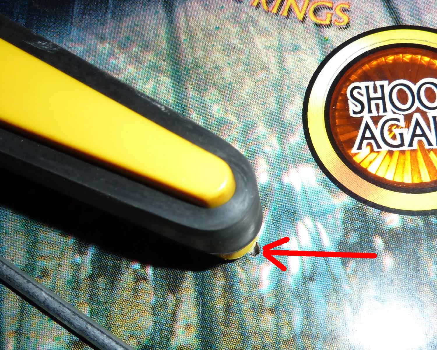
Note (in the picture) that this low power EOS switch shows almost no wear. It belongs to a Williams / Bally Fliptronics pin. These are recognizable because the switches are open when the flipper is at rest. These switches can last longer than the linkage.
This (see photo) is a flipper switch for an early fliptronics game such as The Addams Family. Some fliptronics games used optical switches on the flipper buttons that do not have metal contacts.
More information on Fliptronics plus DE/Sega/Stern solid state flippers.
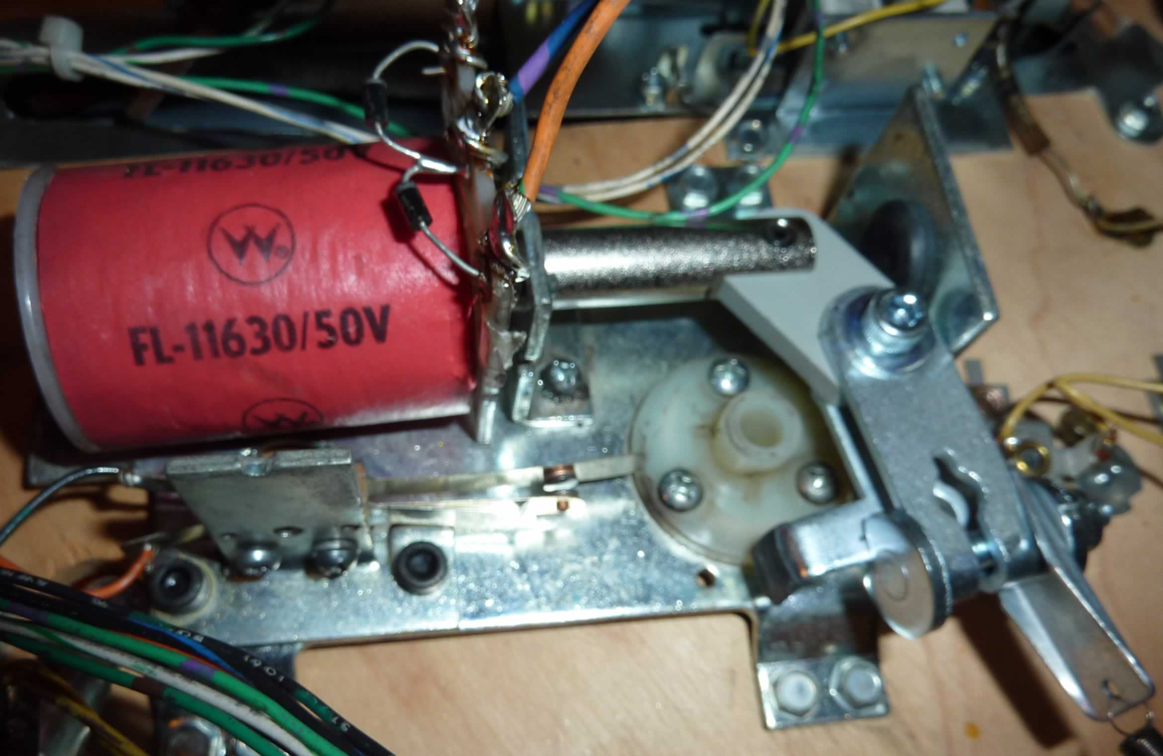
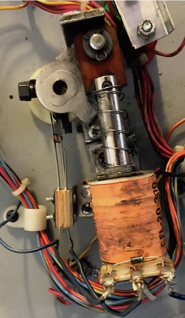
How To Rebuild Pinball Machine Flippers
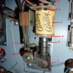
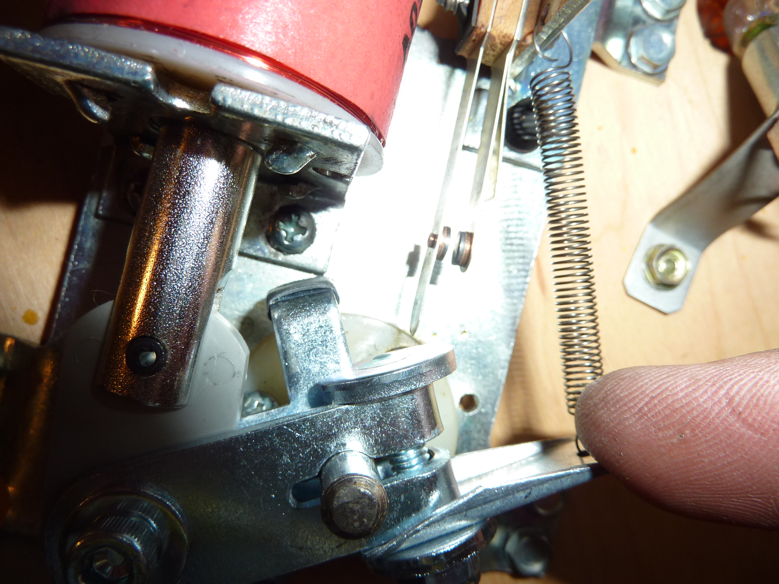
This is a typical setup in an EM or early SS pin.
(click on the photo for a larger image)
Prior to beginning disassembly, pull up and down on the flipper itself. Notice that there is a small amount of vertical movement. When re-assembling, it is crucial that there be a little bit of up and down movement on the flipper bat, or the mechanism will bind and not swing freely.
The procedure for EM, early full power SS, Fliptronics and DE/Sega/Stern flippers is nearly identical. The only difference is the treatment of the switches. Never use anything abrasive on Fliptronics or low power DE/Sega/Stern flippers.
Steps: Caution: Insure the machine is turned off and unplugged.

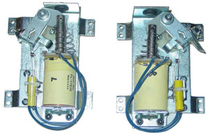
 1) Remove the flipper by loosening the nut holding the flipper bat shaft. Some flippers are held in place by two set screws and an Allen (hex) wrench is required. Others are held in place by a combination of a nut and an Allen bolt like the Williams assembly to the right. Some require only a socket wrench to loosen.
Note: At this point, it is possible to unsolder the two wires coming from the playfield wiring harness to the coil and remove the entire flipper assembly. This makes it much easier to rebuild the flippers. If doing so, take photos to insure that these two wires are soldered to the same tabs on the coil. Wiring backwoods will cause a short.


2) Remove the flipper coil stop (#1 in the above ‘Components‘). This may require a nut driver or allen wrenches.
3) At this point, the solenoid coil and crank assembly will no longer be held in place. Remove the coil from the plunger and let it hang by the wires (unless you unsoldered the wires).
4) Use your needle nose pliers to disconnect the spring from the base.
5) Clean out the bushing hole for the flipper shaft. We use several q-tips or a towel and small amounts of isopropyl alcohol. Some kits include a new bushing. Note, if the flipper dragged on the playfield, likely cause was this worn bushing. Replace it. Most of the time, this bushing does not require replacement.


6) Inspect the diodes on the coil. Carefully insert a small screwdriver behind the diode and push slightly to see if it is broken. If one is broken or suspect, replace it. Note that some coils have two diodes, others just one and some do not have any at all.
7) Replace the coil sleeve. Check to see which end of the coil has the sleeve with the collar. Press out the sleeve from the other side, then insert the new one with the collar on the same side. It maybe impossible to remove some sleeves. That is usually because the coil overheated and is ruined. Replace the coil and use a new sleeve.
8) There is a left and right crank assembly. Compare the new ones with the one you have removed and select the identical one. Attach the new spring (to the plunger or to the tab, depending on your type of spring).
Note: Some flipper systems have the spring on the shaft. If yours does, be sure to insert it through the plunger. The larger loops go towards the coil.

Here is the only tricky part – insert the crank assembly through the solenoid bracket, (add spring now if like that to the left) then into the coil (diode / wire end towards the crank assembly, if possible).
Hold all three parts together and insert the coil into the new coil stop from step #2. While holding this all together, manipulate the crank assembly into its proper position so that it is ready to be connected to the flipper bat shaft. If this assembly had a spring on the plunger, be certain to install it prior to inserting the Crank Assembly into the coil.

9) If the original coil stop had a washer / spring attached, set it on the new one. Attach the new coil stop, removed in step #2, to the base plate. At this point, all components should be held into place.
Replacing the EOS Switch – Soldering Iron Required
Types of EOS Switches:

a) Simple high current switch made of tungsten
b) Complex high voltage switch (see Bally linear flippers, above) which includes an upper flipper switch (tungsten) or a lane change switch (low power)
c) Simple low voltage switch (usually ’92 and later).
Types a) and b) are closed when not in use. In b), the upper flipper or lane change part of the switch will be open.
Type c) will be open when the flipper is not in use (normally open) in the Williams / Bally Fliptronics pins. In other pins, like DE/Sega/Stern, EOS switches are low voltage, but are closed when the flipper is not in use (normally closed).
Note: If there are two switches on the flipper, it is crucial that they be wired exactly the same way and physically in the same location on the bracket. The NC EOS switch must open when the flipper is activated. And the NO second switch must close when the flipper is activated.
Note: We found some EOS switches have an oil on it that must be removed for the flipper to have full power. A Q-tip and Isopropyl Alcohol on the contacts will quickly do the trick.
10) Note the orientation of the EOS switch, which side faces the coil and which leaf is hit by the flipper as it opens. Remove the screws holding the switch. Leave the old switch dangling by the wires.
11) Mount the new EOS switch in the same orientation as the old one. Tighten the screws firmly.

12) One at a time, unsolder the wires from the old switch and attach them in the same place on the new switch. If there are only two wires, location is not crucial. But if it is a multilevel switch, it is crucial that the wires be connected to the same tabs.
Make absolutely certain that none of the wires from the EOS switch are touching or shorting anything else. On many systems, these wires carry high voltage and can fry other components.
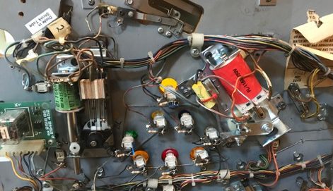
Adding the Capacitors
Do not add capacitors to Fliptronics nor any DE/Sega/Stern game that has computer controlled flippers.
Check your manual to see if a capacitor is required. Parallel coil flippers that are not solid state computer controlled require a capacitor.
We go further and suggest that even early games with serial coils such as early Bally, Stern Williams and Gottlieb add capacitors to the EOS switches.
Attach the caps to the EOS switch bracket and hold it in place with a zip tie. We slide thin shrink tubing over the bare capacitor wires, then solder the wires. Most people solder both wires to the EOS switch. But we attach only the wire that is closest to the EOS switch. The other wire goes to the coil to the other wire from the EOS switch.
The capacitor can be installed in either direction as it does not have polarity (no + or -).
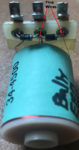
This picture shows an early Bally game with three flippers. That second switch attached to the EOS switch activates the upper flipper. We added a 0.1uF 500V disc capacitor to that second switch to reduce the spark.
Final Assembly and Installing the Flipper Bat
If you removed the assembly from the playfield, reinstall it now and solder back the wires.
Make certain that the springs are attached to the linkages.
13) Insert the flipper bat shaft through the playfield and into the crank assembly. Tighten the shaft so that it is secure, just enough that it cannot fall out.
Do not tighten fully. We will align the flipper in later steps. If you have a flipper gauge, you can use it here. Or save it for later in the final alignment steps.
14) If spring is outside the plunger, attach it the other end to the bracket. Needle nose pliers make this step easier.
Adding Capacitors to the Cabinet switches
The 0.1uF disc capacitors should be added to the cabinet flipper switches.
Do not add capacitors to the cabinet switches for games with computer controlled flippers or opto flipper boards.
Tightening the Flipper Bat
At this point, the flipper bat shaft should be firmly, but not tightly, connected to the crank assembly in step #13. Check its position in the playfield. It should be possible to swing the flipper bat into various positions.
15) While holding the flipper mechanism in the closed (at rest – power off position) below the playfield, swing the flipper bat above the playfield. If the bat turns too freely, tighten the screws or bolts holding the shaft in place. If it is difficult to turn, loosen these screws or bolts just a little. Make certain that there is a little up and down movement. Use the Flipper gauge if you have one.

16) Swing the bat into the desired position. If there are small markers in the playfield, the bat should either point at the marker, or rest on it. If the alignment point is below the flipper, insert a toothpick into the marker and set the bat against the toothpick (without the rubber). If no markers are present, set the bat parallel to the wire on the playfield.
17) Tighten the bolt / screws on the crank assembly. If after a few minutes of game play, the flipper bat starts to shift position, it was too loose.
It is possible to over tighten the type with a bolt (Williams WPC). Some people will crank those so hard, that the two pieces bend and touch each other – don’t do that.
Flipper shafts held in place by one or more Allen wrench screws usually have an indent in place, making fine adjustment difficult. If so, switch the left and right flippers and make a new indent. Or replace the flipper bats & shafts.
Adjusting the EOS Switch
| 18) Crucial: Check the EOS switch adjustment. For non-Fliptronics pins, the EOS switch must open when the flipper is activated (up). The EOS switch should open as late as possible so that full power goes to the flipper as long as possible. But the switch must open completely or the coil will burn and/or arcing will occur and ruin the EOS switch. Nominally, the EOS switch should open ~ 1/8″, but we do this by eye. |
If you are new to adjusting EOS switches, please consult our guide. Note that the stationary leaf must hold the inner leaf in place. When the EOS switch closes, the two leafs must be pushed together.
It is crucial to get this adjustment correct, or your flippers will not operate properly.
For Fliptronics EOS switch: switch is open when the flipper is at rest. Closes when the flipper is fired. Note that that this is the opposite of what happens with older style full power flippers. Adjustment is so that the switch starts to open as the flipper starts to fall back from fully open. The only purpose for this EOS switch is to tell the computer that a force is pushing the flipper closed (such as trapping 3 pinballs) and the computer increases the power to the flipper. And improperly adjusted EOS switch cannot cause Fliptronics flippers to be weak.
For DE/Sega/Stern EOS switch: if the flipper coil has only two wires, then these flippers are also computer controlled, but the EOS is adjusted like an older style flipper. The EOS should be closed at rest. The EOS will open when the flipper is activated. This EOS works like the Fliptronics, telling the computer that the flipper is being forced closed and to add more power to the coil. And improperly adjusted EOS switch cannot cause DE/Sega/Stern computer controlled flippers to be weak.
If your DE game has three wires, then the flipper is not computer controlled and the EOS switch should be adjusted just like all earlier pinball machines.
If your flipper coil has two switches then the NC (normally closed) switch is the EOS switch. Adjust as above (non-fliptronics). But the second (outside) switch must close. It should close after the EOS switch opens. That way the second flipper does not pull full power while this flipper is opening.
If there is not an upper flipper, then this switch may activate the lane change. Adjustment is not as crucial and the switch just needs to close as the flipper opens.
19) Rebuild the other flipper. When finished, the two flippers should sit at the same angle. Try playing the pin. Readjust the position of the flippers if they seem incorrect to you. I mark the date if flipper rebuilding with a sharpie on part of the metal (not the coil or plunger).
Update Fippers to The Best Style
Most owners rebuild the existing flipper mechanisms in their machines to the original specifications. However, earlier flipper mechanisms had their limitations.
Note that this section only applies to Bally, Stern, and Williams and early DE solid state pinball machines.
Do not make this change with Gottlieb (we don’t have any experience).
Do not change flipper mechanisms in computer controlled DE/Sega/Stern nor any machines with only two tabs on a flipper coil.
We doubt this applies to any EM games, but have not tried it since most are AC.
Pinball games newer than ~1992 should retain their mechanisms.
WPC Style Flippers
If your Bally or Williams pinball machine was built prior to 1988*, chances are you have old style coils, poorly designed springs and weak EOS switches that burn out quickly. Flipper rebuild kits for 1975 to 1988 pins cost from $40 on up. However, WPC pre-Fliptronics kits for Bally / Williams pins cost only $20. After the initial installation, there is a 50% savings with each rebuild!
Or looking at it another way, you can spend $40 on a rebuild kit. Or $80 on a conversion to WPC and have a new coil and coil bracket, superior spring and EOS, then half-price rebuilds from then on.
*Williams pinball machines after about 1983 have 50 V DC parallel coil flippers and are quite good, except they have that crappy spring on the plunger. WPC style flippers have the spring off the plunger linkage, to the side. Upgrading to the external spring provides some improvement and can be rather easily accomplished by installing new WPC style linkage, adding the external spring, plus drilling a small hole (or replacing) the EOS switch bracket to connect the spring. It is not necessary to replace the flipper base plate nor any other parts.
Serial vs. Parallel Coils
If your coil has a single diode, then it is a serial coil. If it has two diodes, it could be serial or parallel. Parallel coils have two wires to the left lug. Series coils have two wires going to the center lug. Parallel coils used in non-Fliptronics pins must have a capacitor on the EOS switch and the flipper switch.
Why Parallel Coils?
There is some evidence that EOS switches with a capacitor and parallel coils will last longer.
Why WPC Style?
Besides the cost of rebuilding, older style flippers have inferior springs. Many of them have springs on the flipper coil and plunger. Those springs break easier and tend to tear up the mechanism. WPC flippers have springs outside the flipper which last longer and make the flipper feel more snappy.
Other Differences

While wiring will go to the same lugs, what happens is a bit different. In older serial coils, the EOS switch shorts out the ‘hold’ coil. Opening the switch sends current through both the ‘power’ and ‘hold’ coils which drops the current / power.
In parallel coils, the EOS switch connects the current to the ‘power’ coil. Opening the EOS switch removes the current from the ‘power’ coil. The power is always traveling through the ‘hold’ coil. Since these two coils collapse at different times, two diodes are needed.
Downsides and Complications
This conversion works well for early Williams SS pins running at 28 volts but improvement is more modest. It works great in early Bally / Stern pins running at 43 volts.
The flipper base on these style flippers is a bit larger than the area occupied by older flipper systems. Some of the old ones did not even use a plate. That can make locating this flipper plate difficult or impossible in some pins.

If the original flipper bats have an indent on the shaft, then they must be replaced. The WPC style linkage has a clamp to connect to the flipper shaft. If the flipper shaft has an indent then the clamp cannot be tightened enough to keep the flipper from slipping out of position.
In other pins, the plate may have to be turned and located in a different direction. In that case, the wires may not reach the new location. When adding an extension to the wires:
-
- Use heavy gauge stranded wire (see photo).
- Insert shrink wrap tubing over one end of the wire.
- Twist the wires together tip to tip, so the wire looks like an extension.
- Solder the wires together.
- Slide the shrink wrap tubing over the patch and heat the tubing with a heat gun, (maybe) a hair dryer, or [?].
Converting Different SS Pinball Machines
The entire mechanism for early Williams and Bally SS pins will be replaced. Use the ordering information below.
If updating Williams System 9, 11 and early WPC flipper mechanisms with older style springs on the plunger, you already have the correct coils. It is possible to drill a hole in the EOS bracket to accept the spring, or order a new base plate, then install the spring, capacitor, and rebuild the flipper.
No conversion information is available for Gottlieb, EM, and DE/Sega/Stern pins. Sega Stern pins with solid state flippers are good as is.
Ordering Information
The parts needed can be ordered on any pinball parts supplier. But the easiest is to order them from Pinball Life, where they have complete assemblies.
Full Right Flipper Assembly and Full Left Flipper Assembly are listed separately.

Note that Pinball Life seems to have made ordering this a little harder recently in that they default to the Fliptronics EOS switch. Always update to the normally closed (NC) EOS 03-7811 switch. Normally open switches are for Fliptronics and those cannot be used here. You will also need to select the appropriate coil and coil stop (see below). It is also recommended to purchase the EOS switch capacitor.
Options
Coil – Check your solenoid voltage. If converting an older Williams System 3 – 7 game, your solenoid voltage is 28 VDC, then select the SFL 19/400 – 30/750 coil*. Early Bally / Stern SS pins had 43 VDC solenoids. This is not quite as high as the WPC pins that had 50 VDC, so slightly more powerful coils are used to compensate. If FL23/600 – 30/2600 use a FL11630. A FL24/600 – 30/2600 calls for a FL11722.
* Note that Williams changed the flippers to 50V DC in the middle of the system 7 production (on ~1983 and later games), so check your machine. If it has 50V DC, then if FL23/600 – 30/2600 use a FL11630. A FL24/600 – 30/2600 calls for a FL11722.
EOS Switch – From the drop down menu, select the 03-7811 normally closed EOS switch.
Coil Stop – We use A-12111. A comparison of coil stops.
Base Plate – Order a left plate and a right plate for each pair of flippers. If there are upper flippers, it will be important to specify whether that is left or right.

Capacitor – The kit does not come with a capacitor. Order one for each flipper and install it on the EOS switch. You will need a cable tie to hold the cap to the bracket and/or double sided sticky tape (we usually skip the tape), and shrink wrap tubing to insulate the wires.
Flipper Bat – Don’t try to reuse the old one as most are designed for set screws with an indent. The ‘clamp’ style WPC linkage will not hold the shaft securely because of the indent. A generic no logo one is fine, unless you really have to have that company logo.
The flipper assembly comes with flipper bushings, so no need to order separately.
Bally Secondary End Of Stroke Switch – Normally Open – For early Bally pins with an upper flipper, this switch must be added to the lower flipper’s EOS switch. This is how the upper flipper is activated. You will also need longer #4 screws. We used 1″ #4 screws and nuts but 1&1/4″ #4 machine screws and nuts should work with the existing hardware.
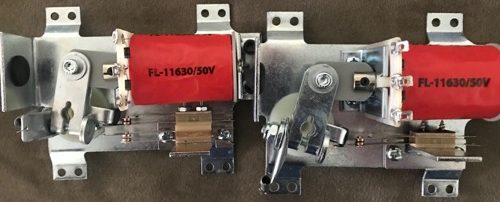
Install of WPC Flippers on Bally Eight Ball Deluxe
Eight Ball Deluxe is a beloved early Bally SS pin. Unfortunately, it uses linear flippers. Linear flippers wear more quickly and the rebuild kits are far more expensive.
Many people ‘downgrade’ to the early style Bally flippers, which is fine. In our case, the flipper brackets were damaged and had to be replaced. So we decided to install WPC style using the parts above.
Above is a photo of the install of the right flipper vs. the existing linear left flipper. It would not fit in the same orientation as the original, which was almost vertical. It was easy to rotate it slightly to the left. We needed to miss two lamp sockets. We also had to move a wiring harness wire holder and rotate the fuse holder slightly – all easy to do.
We played several games with the original on the left and the new on the right. Both seemed equally powerful. The WPC flippers are quieter and do not have the ‘thunk’ of the linear flippers.
Be sure to replace the flipper with a style that does not have the indent on the shaft, otherwise the WPC style clamps will not hold the flippers well.
For the left flipper, we will need to move the relay board down slightly – also not a big deal.

The photo shows what we had to do for the lower left flipper. These Bally machines with an upper flipper have the flipper switch located next to the EOS switch. We removed the EOS switch bracket, flipped it around, and reinstalled it to give us room for two switches. We replaces the screws and used 1″ #4 screws and nuts. We should to install two caps on that flipper – one for the EOS switch and one for the flipper switch to the upper flipper. However, the cap on the EOS switch seems to be more important than the cap on the NO switch that activates the upper flipper – and we don’t know why. That NO switch does not seem to wear rapidly without the cap, while the EOS switch does.
External Links
How a Flipper Works – Steve Kulpa’s great explanation. [Steve’s website is down as of 2020. He has allowed us to reproduce it on our website.]
Parallel vs. Serial Coils – A group discussion on the differences between coils.
Coil Cross Reference – Extremely helpful information about pinball coils and cross references from Pinball Medic.
Copyright 2006 – 2025, all rights reserved.
Comments
Comments, including suggestions, improvements, errors, etc. are welcome (see below).
If you have a specific question about your game that does not directly apply to rebuilding flippers, please see our FAQ section.
Great help so far. I’ve gotten a “dead pin” running with your help. But now I’ve hit a snag that I’d like to ask a question. I have a data east “jurassic park” machine. With your help, I’ve located two bad circuit boards = play field power supply and the main power supply. I fired it up and started playing all looking good. I got a couple of minutes of play time when the left flipper quit and the upper flipper quit. The right lower flipper continued to work. Just looking for obvious signs, I noticed the left flipper plastic (yellow) seemed dark maybe burnt compared to the other two. Looking for heat, I checked the flipper control board for blown fuses = none. However, the board has visible burned damage (like the previous two boards). I’m ready to buy and plug in a third board. I read the DE service bulletin with the upgraded board. My machine already has the upgraded board from the factory (still has DE stickers on it). I understand all you’ve posted about the mechanical aspects of rebuilding these SS flippers, that’s well within my mechanical ability. My concern is what caused the current flow that burned this board. I don’t want to burn up a new board. Can you point me in the right direction?
“However, the board has visible burned damage (like the previous two boards).”
It would be helpful to know what has burned up.
By the upgraded board, we assume that you are referring to, “Data East made a mistake in their first few games (Jurassic Park, Last Action Hero and Tales From The Crypt) and those flippers will not operate properly if the EOS switches are broken or out of adjustment. Later Data East machines did not have this problem and the flippers could continue to operate with defective EOS switches. How to modify early Data East solid state flipper boards.”
https://homepinballrepair.com/how-sold-state-flippers-work-fliptronics-de-sega-stern/#desega
If that board has been properly modified, then the EOS switches should not cause the problem.
Burned up components means that something is drawing too much current. In this case, it usually means that the flipper coil is defective. Flipper coils usually do not fail. And when they fail, the wire breaks and they stop working. But sometimes, a coil that is overheated will cause the insulation within the coil to melt and short the windings of the coil together. That means that the resistance drops and too much current flows. The best way to check that is to check the coil resistance. Compare all three. You should unplug CN2 from the flipper control board prior to measuring resistance.
What we don’t like is that two flippers quit. That board is capable of running three flippers and the circuits are separate. If you have two damaged circuits, either that means that you have two damaged coils (possible, but unlikely) or something else is causing the failure.
Upper right comes from CN2-1,2. Right comes from CN2-7,8.
Let us know what burned up on that flipper board and get back to us. In the meantime, we will do some digging too.
Could an EOS without fish paper on it cause a weak flipper? I replaced the EOS on my DOOZIE and the flipper is weak. The replacement did not come with fish paper between the blades but the original has it. could this cause an issue with flipper power?
I have replaced the coil, bushing, plunger, etc as well as the cabinet switch.
Most of the time, the fish paper is there to prevent the power from shorting to the flipper mechanism. It should be on the EOS switch, otherwise you run the risk of having that power applied to the entire flipper mechanism. That could cause a shock or a short.
But we find it difficult to believe it would cause the flipper to be weak. We are guessing that the EOS switch needs to be cleaned (try isopropyl alcohol) or the contacts are not touching flat on the switch – although they should on a new switch.
We are guessing that the cabinet flipper switch is worn / pitted. It maybe possible to file those tungsten contacts.
There is another possibility that you have a frayed wire someplace. Or there is resistance in the Jones plugs.
We would clean and inspect the EOS switch and make certain it is making good contact when it is closed. Also compare the wiring to the coil on the two flippers. Possible that one is wired wrong?
Also confirm that the flipper moves freely. A common mistake is pulling down the flipper itself too tight to the bushing so it binds. It may feel like it is moving freely, but if you cannot pull up and down and feel that it is loose, then the flipper is binding to the bushing.
Then we would use a clip lead with a good sized wire and try firing the flipper with by shorting the contacts on the cabinet flipper switch to see if it stronger than pressing the switch. If it is, then file / clean the cabinet switch or replace it.
If that does not work, put a clip lead across the EOS switch and BRIEFLY hit the cabinet flipper button. Do not hold it in as you have bypassed the EOS switch and will burn up the coil.
If that does not work, then it is either physically binding, wired wrong, coil is wrong / bad, not getting full power / ground and the wiring is suspect.
Well, I did everything you suggested (except cleaning the cab switch as it is brand new). I ended up desoldering all the coil wires and re-soldered them. I works now. Thanks again for taking time to reply to my questions
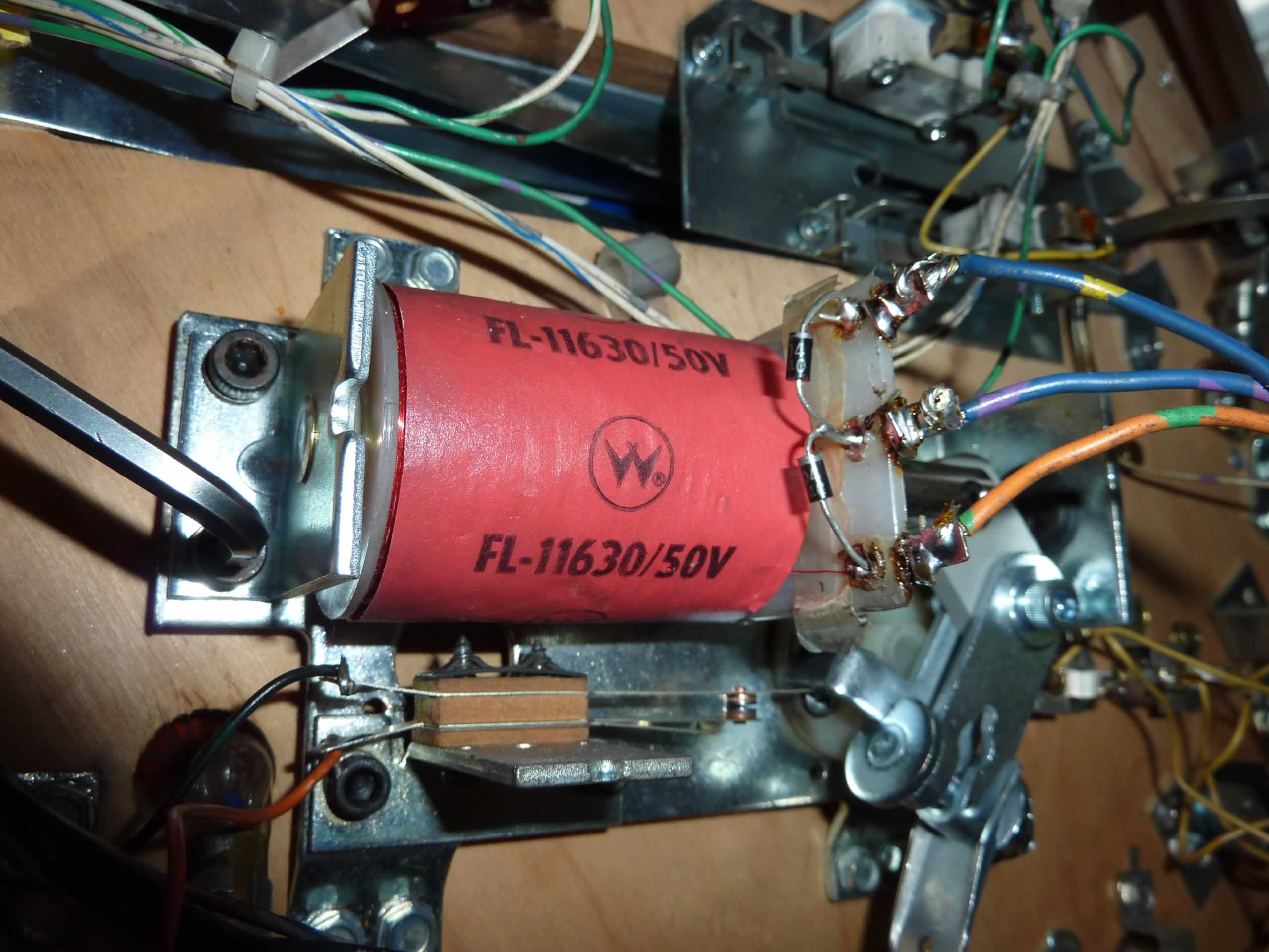
i have a 1980 Bally Skateball, I am having trouble with the upper right hand flipper, at one time everything worked correctly. Now the upper right flipper is very weak, when I hit the button, the flipper will make 1/2 swing or less, I can’t get a full strong swing. I’ve replaced the plunger, sleeves, etc with a rebuild kit and it does the same. I’ve adjsted the switch but still have a week swing. Do I need to replace the coil or am I loosing power somewhere else. I’m not real proficient with electricity but can understand the mechanics of how things work. Any suggestions will be helpful. thanks
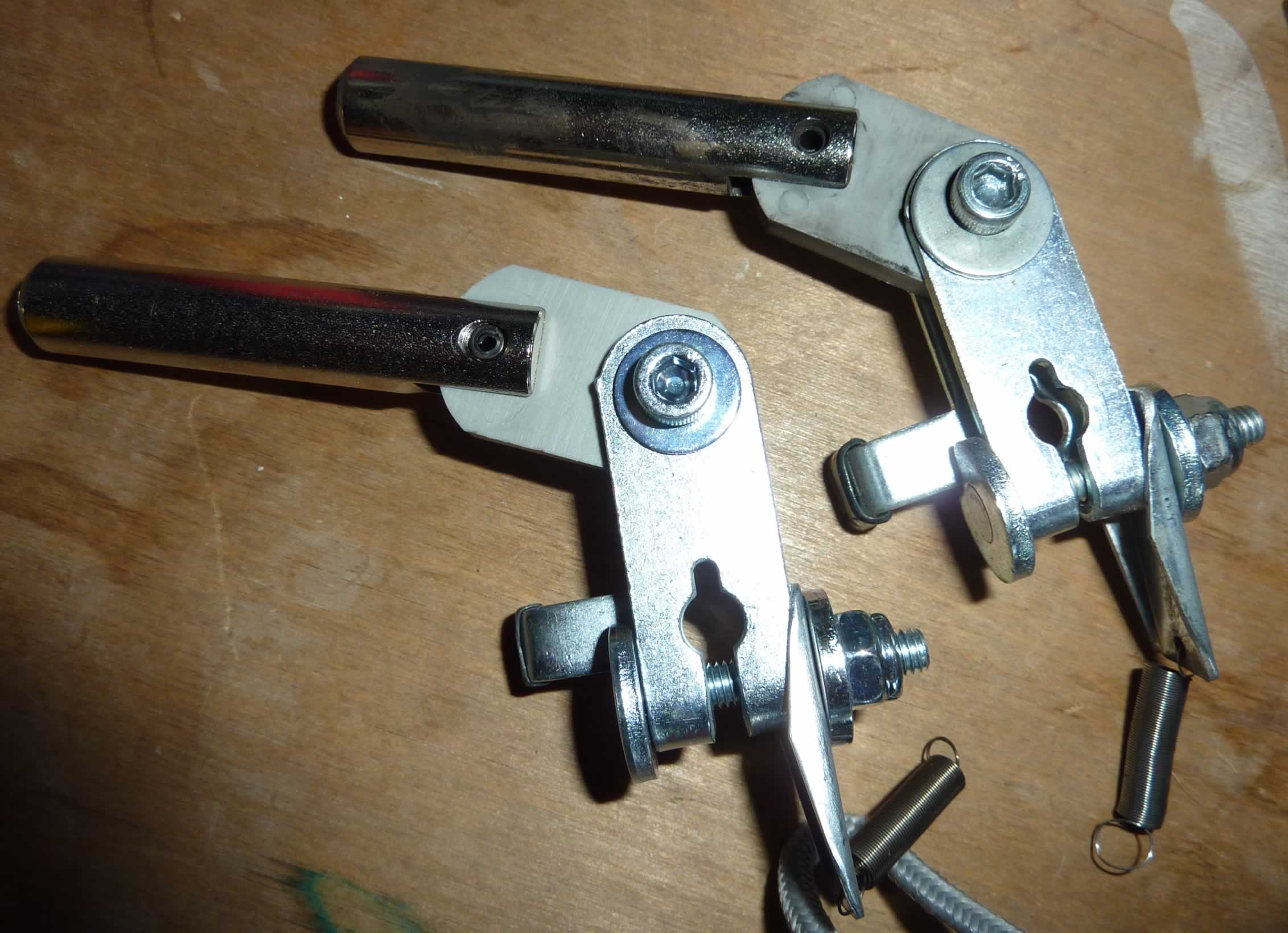
Please take a look on the page you posted on. Starting in the section, “Rebuilding the Flippers” and there is a photo of what we link your lower right flipper looks like.
The caption on that photo says “The open switch activates the upper flipper. That must be replaced also.”
There are two switches. The one that is normally closed (NC) is the EOS switch for that lower right flipper. The normally open switch (NO) upper switch is what activates the upper flipper.
There are important rules to make this work for the upper flipper. Ignoring what activates the lower right flipper for the moment, be sure that:
1) That normally open switch is new and the correct one. Sometimes people put low power gold plated and they will not work. It has to be the tungsten high power switch. It must be cleaned with isopropyl alcohol if it is new.
2) It must be wired correctly.
3) It is supposed to be adjusted so that as the lower flipper activates and opens, the EOS switch on that lower flipper opens, then that other NO switch closes. That is done to insure that the high power portion of those two coils is not on at the same time.
4) At that point, power is sent to the upper switch. It must have a properly operating EOS switch that is closed. If it is a new switch, which it should be, insure that it is wired properly. Clean the contacts with a Q-tip and isopropyl alcohol (not rubbing alcohol which might contain lanolin).
5) Check to be certain that the correct spring is on the upper flipper. If the spring is too strong, the flipper will be weak.
6) Insure that the correct coil part number is on the upper flipper.
7) If all of this does not help, with the power off, check the resistance of the coils and compare. You will need to put a piece of paper between the EOS switch contacts.
8) Also insure that all wiring is well soldered and there are not any broken strands of the wire where it is soldered. If there is any doubt, unsolder the wire, cut off the end of the wire, twist the wire together, tin the wire with solder, then reattach. Be sure to use wire cutters that do not nick or break the strands of wire.