Bally Driver Board ’76 – ’85
Note: The Bally / Stern Solenoid Driver & Voltage Regular Board serves two functions: Control the solenoids, and supply the +5, +12 V DC and display voltages. This page only covers the solenoid driver board section.
Solenoid Driver Section
Troubleshooting a failed solenoid is similar to the Bally lamp board. In the case of a failed right slingshot, the power comes in J5-15 and is controlled by Q10. Q10 is turned on and off by the output of U2 pin 13, via U3 pin 8 in and out through 7.
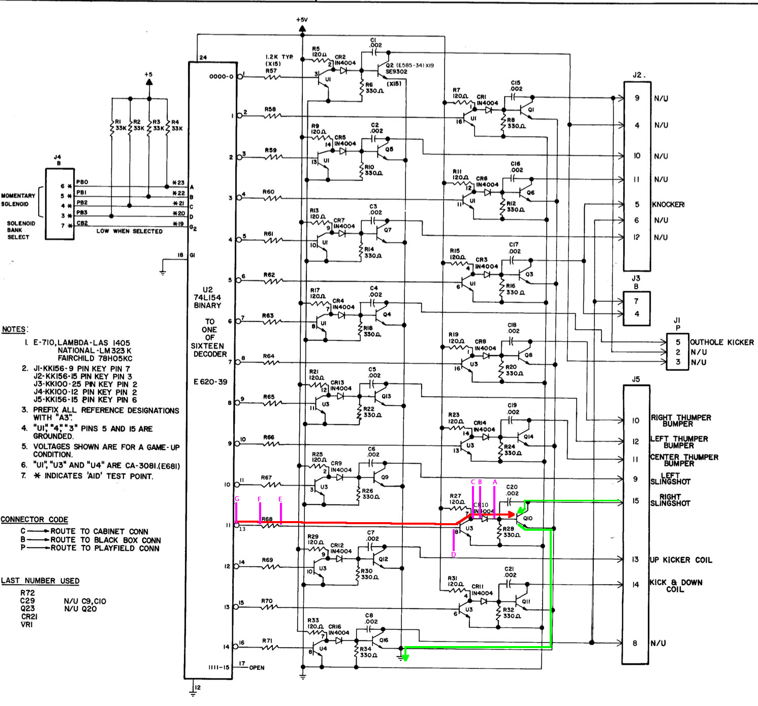
Prior to using the digital logic probe, it is assumed that you have done typical troubleshooting, which would include shorting J5-15 to ground (or the tab on Q10) to insure that the slingshot fires. This proves that the power supply and wiring is good.
Also, using your DVM, insure that ~43 VDC is not present at either side of the diode CR10. If it is on the banded side, then Q10 is shorted and must be replaced. Failure to check this could destroy your probe. If +43 VDC is on both sides, U3 is likely fried and the diode is bad.
After confirming that there is no high voltage present at diode CR10, we can safely hook up the digital probe (see “Using the Probe” above). Connect the probe to +5 VDC.
Turn on the power, enter the service menu and set the solenoids firing. The solenoids will fire in order. From the manual, the Right Slingshot is 04. When 04 fires on the menu, we should see a signal as drawn in the diagram (above).
Set the probe to point “A”. If there is a signal there but the solenoid does not fire, then Q10 is likely defective. Confirm with your DVM that there is a connection between Q10 and J5-15, Q10 and the diode, and Q10 and ground, prior to replacing Q10.
If no signal at “A”, test “B”, the non-banded side of diode CR10. If signal there, the diode is defective. This is unlikely, so check your work. If the diode is bad, are you sure that Q10 is not shorted? Also check R28. A bad R28 will act like a bad diode to the probe.
If no signal at “B”, check “C”, pin 7 of U3. If signal there, the trace / solder is bad between U3 and diode CR10.
If no signal at “C”, test “D”, pin 8 of U3. If signal is there, U3 is likely defective. Confirm that other solenoids using U3 work prior to replacing it. Also check R27. A bad R27 will give the same indication as a bad U3 to the probe.
If no signal at “D”, test “E”. If signal there, trace / solder is bad between R68 and U3-8.
If no signal at “E”, test “F”. If signal there, R68 is open, or more likely a bad solder joint.
Signal at “G”? Then a broken trace between U2 and R68. If no signal at “G”, U2 pin 13, then U2 is likely defective. U2 is a decoder chip – see the Decoder Chip section. If one of the connections to it (pins 12, 18 – 24) were bad, many of your solenoids would not work properly.
Bally Driver Board ’76 – ’85 Test Procedure
Solenoid is not firing. A “Yes” means pulse; or switch from high to low, or low to high. Confirm no high voltage at (A) before proceeding. See photo for test points.
1) Test (A) – Yes = Replace Q10 (check traces first) – No = Test (B)
2) Test (B) – Yes = CR10 defective (check solder) – No = Test (C)
3) Test (C) -Yes = bad trace / solder -No = test (D)
4) Test (D) – Yes = U3 bad (check R27) – No = Test (E)
5) Test (E) -Yes = Trace / solder bad R68 to U3 -No = Test (F)
6) Test (F) -Yes = R68 / solder bad -No = Test (G)
7) Test (G) – Yes = Bad solder/trace U2 to R68 – No = U2 defective. See decoder ICs