B. Solid State Troubleshooting
1) Early Bally / Stern
– Voltages Required
– Solenoids
2) WPC Bally / Williams
3) Williams 11
4) Williams 3 – 7
5) DE – Sega – Stern
– DE / Sega V3 & 3B
– Sega / Stern Whitestar
C. EM‘s
This covers Bally pinball machines known by the shorthand -17 which were made from 1976 – 1979, -35 which were manufactured from 1979 – 1985. Also covered were early Stern SS pinball machines known as M-100 and M-200.
This section covers checking to insure the voltages are present. It also covers troubleshooting non-working solenoids.
Prior to starting, check the tools required and cautions.
Understanding the Layout
The pinball machine must have power at the right voltages in order to start up (boot). Only three voltages need to be present for the machine to start (boot):
1) +11.9 VDC (nominally +12)
2) +5.0 VDC (between 4.9 – 5.2)
3) +43 VDC (solenoid voltage)
The other voltages have to be there for the game to play. But those do not have to be present for the game to boot.
To troubleshoot, the power flows as follows:
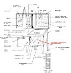
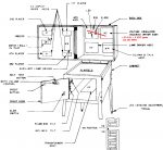
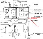
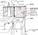
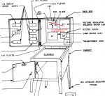
Images 1 – 3 show Bally & Stern pinball machines where the transformer is below the playfield, in the cabinet. Images 4 – 6 show those where the transformer is in the backbox (head).
Testing the Rectifier Board – Images 1 and 4
In this step, the power comes in from the wall (usually 120 or 220 VAC), through a fuse and filter, to the power transformer and to the ‘rectifier board’. Boards located in the backbox are referred to as “-18” boards. Those located in the cabinet near the speaker are called “-49” or “-54”.
Note that these boards have very high voltage present (between 180 – 240V). That can kill. Read the caution section before proceeding.
What can go wrong
1) Connectors burned or fail. Common. Visually look for burned connectors. Will be checked further under voltage testing.
2) Rectifiers fail. Common. Will be checked with voltage testing.
3) Board failure. Burned traces. Bad connector pins. Common. Will check visually and resistance.
4) Fuse blown. Common. Can be a bad fuse. Or another issue like a blown rectifier.
5) Main fuse is blown. Unlikely. Unplug the power, remove and check the fuse in the can in the cabinet.
6) Transformer fails. Extremely unlikely. Will be checked under voltages.
Solutions
Look for burned connectors. These are especially common on machines with the transformer in the backbox (Image 3), but can also occur with cabinet transformer models. If the connectors are visibly burned, replace the plugs and board connectors. To replace the plugs, you will have to crimp new plugs.
If this is a backbox transformer, rather than repairing this board (which is doable, but a pain), just buy a new board. Cabinet boards are easier to repair, but replacement boards are available, too. Some replacement boards come with new plug housings and crimp connectors!
For this game to boot, it must have good 11.9 V DC and 43 VDC (solenoid). The others should be checked, too, but those two are crucial.
Testing
Steps:
1) Turn power off.
2) a) Unplug all the connectors on the other boards (optional, but a good idea).
Or, unplug J3 Solenoid Driver / Power Supply, J4 MPU, J1 Sound Board (may vary from game to game), each display, J4 Lamp Board, J1 Aux Lamp Board.
b) Image 1 (-49 or -54 boards in cabinet). Unplug all connectors except J5 & J6.
c) Image 4 (-18 boards in backbox). Unplug all connectors except J2.
See caution section above. Voltages are above 200 volts and can kill. Do not proceed unless you are qualified.
 3) Connect voltmeter (DVM) black lead to ground.
a) Image 1 (-49 or -54 boards). Connect to TP marked ‘GND’.
b) Image 4 (-18 board) connect black lead to ground side of R2 or R1 (picture).
4) Turn on power.
5) Make the following measurements (note one is AC, the rest are DC):
TP1 – Image 1 (-49 or -54 boards). 6.5 V DC (5.5 to 7.2 is good). Switched lamps.
Image 4 (-18 boards). 5.4 DC (4.5 to 6.0 is good).
TP2 – 230 V DC Display Voltage**. 200 to 250 V DC is good.
TP3 – 11.9 V DC. Crucial. 11 to 15 is acceptable.
TP4 – 7.3 V AC. 6.3 to 8.3 V AC is good. Note that it is AC, so set the voltmeter.
TP5 – 43 V DC. 37.6 to 48.4 is good.
** Note if you have LED displays installed, this fuse should be removed as high voltage is not needed. Plus it is dangerous.
Conclusion
If these voltages are good, proceed. If not, diagnose the problem. Typically fixing this is to replace the board AND the plug connectors (the plugs themselves). If replacing the board, it is a good idea to replace the plug connectors.
If a fuse blows on this board, it is usually a shorted rectifier. If the voltage is low, it is usually a failed (open) rectifier.
Turn off the power and plug in all the plugs on this rectifier board when completed.
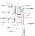
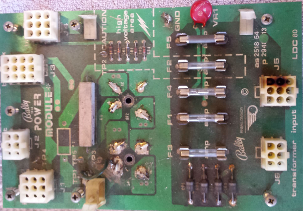
Testing the Voltage Regulator / Solenoid Board – Images 2 and 5
The Voltage Regulator / Solenoid Board serves two functions when it comes to power: +5 V DC power supply, and 190 V DC power supply.
The 190 V DC powers the displays. The +5 V DC power supply is crucial to booting (starting up) the pinball machine.
What can go wrong
1) Connectors. Plugs and header pins. Fairly common.
2) 5 V DC regulator. Common. This LM323 (Bally E-00710) fails with age.
3) Electrolytic capacitor. C23 dries up and fails with age.
4) The high voltage blows out.
Solutions
Many people just purchase a new board. For those who do not do board work, that is fine. But please do not throw this board out. Sell it to someone who can fix it. If purchasing a new board, expect to crimp new plugs. This is especially important with J3 and J4.
This board is exceptionally easy to fix. The fixes usually involve simple steps like replacing the voltage regulator (LM323), C23 and/ or header pins and crimping new plugs. Or resolder where the header pins meet the board and hope for the best.
Testing

It is best to use a ground on the board under test. Once again, Bally did not provide a ground TP (test point). The most convenient spot is the (-) side of the large capacitor C23, but be sure to not short that capacitor. Or the (-) lead of C26. Note that the (+) side of C26 has high (190 V) voltage. Otherwise, use the ground on the rectifier board.
1) Turn off the power.
2) Insure that all plugs are connected on the rectifier board (previous test).
3) On this board, unplug all plugs except J3
4) On the MPU, unplug all plugs (or J4).
5) On the Lamp Board, unplug all plugs (or J4).
6) On the sound board, unplug all plugs except those that go to the speakers (if present) – usually J1.
7) Unplug J1 of the Aux Lamp Board (if present).
See caution section above. Voltages are above 200 volts and can kill. Do not proceed unless you are qualified.

7) If using the ground on the rectifier board, measure ground on the voltage regulator / solenoid board. Either the (-) side of C23, or (-) of C26. Note that the (+) side of C26 has high (190 V) voltage – stay away!
This should read less than 0.1 V DC.
8) TP5 – 11.9 V DC. Same as TP3 from the rectifier board, or at most, down 0.1 V DC
9) TP1 – 5 V DC. 4.9 – 5.2 V. Higher than 5.2 can cause issues with some games booting, especially with aftermarket MPU boards.
TP1 – 0 V AC. (Close to zero.) This is rough measurement of how C23 working.
10) TP3, TP6 & TP 7. All should be the same as TP1. If not, then you have a connector problem at J3. Resolder these header pins, clean the pins (Dremel with an abrasive tool can work) and inspect the plug for any burning and replace if needed.
Note that cleaning these header pins may remove the tin plating – which maybe oxidized anyway.
11) + C23 connector. Less than 0.25 V AC. If higher, replace C23.
Testing the High Voltage
If using LED displays, your high voltage (HV) should be off. If using the old plasma displays, it might be wise to check it. But this could run 230 V and can kill you. See Cautions, above.
12) TP2 – 190 V DC. 170 – 195 is OK. Note that most try to adjust this downward to 170 to 175 to make the displays last longer. There is a small pot (variable resistor) to adjust this. The screwdriver handle must be well insulated.
Conclusion
If all voltages are good, proceed.
If TP5 is bad (and TP3 on the rectifier board is good – those two TP should read the same), you have a connector plug or header pin on this board or on the rectifier board that is bad; or a wire connecting the two is broken.
If TP1 is bad, your voltage regulator is bad. Replace it. Even better, purchase EzSBC as a replacement.
Note: If installing an EzSBC as a replacement for the original LM323 voltage regulator, R49 should be removed. Also, a wire jumper must be installed over across R50 (or remove R50 and replace it with a wire).
This is a switching power supply which means it will run cool and not waste power by creating heat. However, the output might cause noise in the audio board. If that occurs, install a 220 – 1000 25V or higher uF electrolytic capacitor between the 5V output and ground on this board or the 5V input to the sound board. Plus (+) to the 5V side and the minus (-) to ground. For more information consult the Wikipedia page.
Note that because of the way Bally designed this circuit, the +5 may run a bit high. If it is above 5.2, it could cause booting problems, especially with aftermarket boards. Try removing one end of R49 to see if that lowers the reading to about +5.0. Do this in a way that you can reinstall this resistor if this does not work.
If TP3, TP6 and TP7 are low, you have a connector (plug or header pin) issue at J3 on this board.
If the AC at C23 is high, replace C23.
If the high voltage is bad (high or low) then rebuild the high voltage, put in LED displays and sell your old ones, or get a new board.
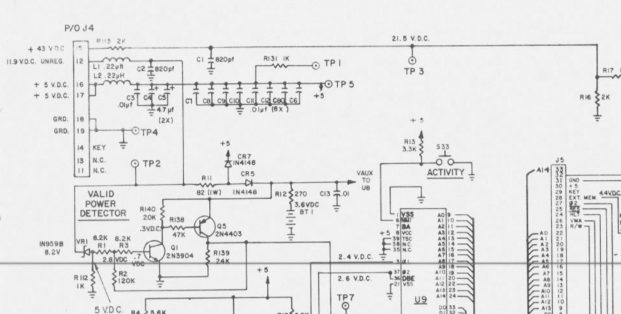
Testing the MPU Board
See images 3 and 6 (above). The MPU board is the brains of this machine. It holds a small computer that has to boot and run properly for it to work.
There only have to be three voltages for this machine to start up: +5, +11.9 and +43 (solenoid). +5 comes from the regulator / solenoid board you just checked.
What can go wrong
1) Connectors (header pins and plugs), wires.
2) Board problems.
This is the final step of this process. If the MPU will not boot (startup) yet the voltages are OK, then it is almost certainly a board issue. These MPUs can be fixed, but that is advanced work. Many people get aftermarket boards.
Testing
1) Turn off the power.
2) Plug in J4 on the MPU board.
3) Confirm that J3 and J2 are plugged in on the rectifier board. J1 does not matter.
4) Confirm that J3 is plugged in on the Voltage Regulator / Solenoid Board.
All Other Plugs Should Remain Unplugged from the Boards.
5) Turn on the pinball machine. If it boots, you should confirm the voltages anyway.
6) Connect the voltmeter (DVM) black ground lead to TP4 on the MPU board. This is ground.
7) Readings:
TP5 / TP1 – 5V DC (4.9 – 5.2) – same as TP1 on the Voltage Regulator / Solenoid board.
TP3 – 21.5 V DC (18.8 – 24.2) – half the solenoid voltage.
TP2 – 11.9 V DC (11 – 15) – The same as TP5 on the Voltage Regulator / Solenoid board.
Conclusion
If these voltages are good, and your MPU does not boot, then you have a problem with the MPU board. Fix or replace.
If these voltages are low, but the testing on other boards were OK, you have a connector (plug or header pin) or wire issue. The 5 V DC comes from the voltage regulator board (J3 pins 14 & 15). The 21.5 V DC is the solenoid voltage divided in half. It comes from the rectifier board (J3 pin 12). The 11.9 V DC comes from the rectifier board (J3, pin 8) via the voltage regulator / solenoid board (J3 pin 12 through pin 13).
If the 21.5 V DC is high but it measures OK on the rectifier board, there is a problem with the MPU board.
If all voltages are low, it is likely the ground is bad. Ground comes from the Rectifier Board (J3 pin 15 & 17) through the Voltage Regulator Board (J3 pins 15, 16, 17; out through J3 pins 18 & 19). If these are bad, the boards can still be grounded through the screws that hold the boards in place and through the metal chassis. But this chassis ground is not secure. If these other wired grounds fail, you will find that your game may suddenly quit or reboot.
Final Step
If your voltages are good and the MPU works then:
1) Turn the power off.
2) Plug in all plugs except J1, J2 & J5 on the voltage regulator / solenoid board.
3) Turn the game on.
Everything should work EXCEPT the solenoids and flippers. The sound board has its own +12 V DC power supply from the solenoid power that we are not checking here.
4) If everything works, turn the power off.
5) Plug in all plugs, including those on the voltage regulator / solenoid board.
6) Turn it on AND listen to insure none of the solenoids lock on. If this happens, you will hear a ‘thud’ as the solenoid plunger gets pulled into the coil.
If a coil stays on, turn off the game immediately and troubleshoot. If left on, the coil may burn up.
Troubleshooting Solenoids
If a solenoid is locked on, see this section.
If a solenoid does not fire, then the issue could be:
* Switches not activating.
* Coil not getting the voltage.
* Transistor is bad.
* Coil is bad (open – check resistance with the power off compared to other drop target coil).
* Thinner wire on that coil, which controls that coil, is broken somewhere – usually at the coil or the plug at the circuit board.
* Plug or header pin bad. These IDC plugs are terrible and those wires come loose or break. Header pins solder cracks.
* Defect on the board or other bad solder joint.
Performing the Solenoid Test
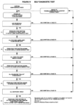

These Bally and Stern pinball machines have a primitive service menu (see the operating manual). To access the service menu, press the red button located on the inside of the coin door three times.
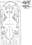
The pinball machine will now rotate through the solenoids. The location of the solenoids are in the manual as indicated on the last picture (above). The circuit diagram will also indicate where, on the Voltage Regulator / Solenoid Board the solenoids are controlled.
If the solenoid in question fires during this test, then the problem is likely to be a switch problem. If it does not fire during this test, skip the switch matrix section.
Testing the Switches
The switches in early Bally and Stern pinball machines are in a switch matrix. For a coil / solenoid to fire, the switch needs to be activated.
The switch matrix test in these early machines is primitive. If there are multiple closed switches, only one will be displayed. For this switch test to work, all switches must be open. The pinball must be removed.
See the ‘Bally Service Menu’ (above) and press the service button four times. If all switches are open – none are closed or stuck closed, there will not be a switch number displayed. Press a switch. The number associated with that switch must light up on a display. See the switch numbers and locations in the above picture.
A solenoid will be activated when a switch is closed. Press that switch and see if it registers. If not, there is an issue with the switch matrix. See the section on the switch matrix. Note that the switch matrix for these early machines is not as easy to interpret as the later more sophisticated pinball machines. The schematic lists the switches in the matrix in a confusing way. Plus, the coin door switches are not included in that diagram, but a separate one.
Note also, that if a coin door switch is stuck closed, that can cause all sorts of odd issues because there is not a diode on (most of) those switches.
Also note that in the case of drop targets resetting, all the drop target switches will need to be read closed. A single one can prevent resetting.
Repair of that switch might require replacement, cleaning, or resoldering / repairing the wires. See the section on fixing switches.
Testing Coil Voltage
Both tabs of every coil must have full solenoid voltage of about 43 V DC (although this may test higher than this value when not ‘under load’). To test:
* Set your voltmeter to DC (not AC!).
* Connect the black lead to ground. Any ground will do, including that ground braid that travels around the backbox and cabinet (assuming it is not broken and the cabinet and backbox braid are connected together).
* Turn the game on. Start a game (flipper coils do not get voltage unless the game is started).
* One at a time, touch either tab on the nonworking coil. Then touch the other. 37.6 to 48.4 is good.
If there is not voltage on the coil(s), go back to the beginning of this page and test the power supply. If all coils except the flippers have power, make sure the game has started. If still no voltage to the flippers, then there is a problem with the relay on the Solenoid / Power Supply Board.
If voltage is present but the solenoid does not fire, proceed to the next section.
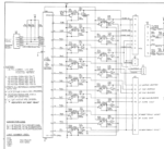
Testing the Transistor Circuit
Note: The flippers are controlled by the mechanical switches located just inside the cabinet from the flipper buttons, not by these transistors.
Each coil is fired by turning on a transistor. The transistor works like a light switch (and the coil is the light). The coil will not fire if the transistor is broken (open) or the wire circuit is broken.
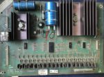
The above photo shows the Solenoid / Power Supply Board. The transistors that control the solenoids are those lined up at the bottom of this circuit board. Each one of those transistors has a metal tab. If we momentarily short that tab to ground, the solenoid should fire.
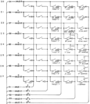
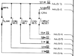
Check the circuit diagram in your manual to identify which transistor controls the broken solenoid. Look on the left side of this diagram as in the second photo. In this example, on plug J2, the chimes are
connected. For example, the ten’s chime comes in J2 pin 9. Follow the drawing and note that it is controlled by Q1. The knocker is connected to J3 pin 4 and is controlled by Q3. The left bottom pop bumper is connected to J5-10 and is controlled by Q13.
STAY AWAY FROM THE HIGH VOLTAGE – this runs the displays and is around 180 V or so. It is potentially deadly. It is also located at the top / left of this board. See the Caution.
Take a heavy duty clip lead and connect one side to that ground braid. Turn on the pinball machine and start the game. Briefly touch the correct transistor. If we touch Q13 in this game, the left bottom pop bumper should fire. If it does not, try another transistor that is being used by the game. If this one fires and the one under test does not, you may have any of the following:
* Coil is bad (open – check resistance with the power off compared to other drop target coil).
* Header pin (that the plug connects to) is not soldered to the board properly. Often called ‘cracked’. Resolder the back of the header pins.
* Thinner wire on that coil, which controls that coil, is broken somewhere – usually at the coil or the plug at the circuit board.
* Plug is bad. These IDC plugs are terrible and those wires come loose or break. Header pins solder cracks.
* Defect on the board or other bad solder joint.
If the coil does fire when you test the tab, then this transistor maybe bad. Replace with a TIP102. Or the IC driving this transistor could be bad.
Comments
Comments, including suggestions, improvements, errors, etc. are welcome (see below).
If you have a specific question about your game that does not directly apply to checking voltages on an early Bally or Stern pinball machine, please see our FAQ section.
I am an electrician trying to help a friend troubleshoot a Bally 8-ball machine. I am getting 4 volts on the MPU board and the LED comes on and stays on never blinking. The self test switch doesn’t do anything at all but when you turn the machine on the back lights all light up but the displays do not work nor the solenoids. Any help would be appreciated
Hi Matt. We generally cannot take the time to respond to specific questions anymore. But we can throw a few ideas out at you.
The first thing to do is check all the voltages. This starts at the rectifier board located near the transformer. There are test points there for you to use. Be sure to see if you are supposed to get AC or DC as one test point is AC. Note that dangerous high voltage is also there, at 230 V DC and ~180 V AC.
From there, move onto the voltage regulator / solenoid board. The +12 and +5 are crucial. If the (nominally) +12 is too low, then the +5 cannot be right. There is a voltage regulator on that board, the LM323, and that is known to fail. But there can be other issues, too, such as the large electrolytic capacitor. And the 0.100 and 0.156 connectors.
Look out for the exceptionally high voltage on that board. There is 230 VDC present there.
Once all those voltages are OK, then move to the test points on the MPU board. That board will not boot if the +5 is below about 4.8.
All of these steps, problems, testing and solutions are outlined on this page for you. If there are sections that are not clear, please feel free to point that out to us and we will do our best to make it more understandable.
For more information, please check out:
https://homepinballrepair.com/troubleshooting-early-bally-and-stern-pinball-machines/
https://homepinballrepair.com/faq-frequently-asked-questions-about-pinball-repair/
I have a Bally Special force pinball, and the game works fine as intended, but the transformer started to smoke last time I turned it on. Again, functioned as normal that day and after a couple hours of being on, the transformer smoked. Is it failing? If so, must the new transformer match the old one exactly (part #) or can any transformer with the same voltage lines be spiced onto the harness for the game?
Matt, that is terrible news. That should never happen. There is a fuse on the input. And each output of the transformer has a fuse also in order to protect the transformer. It almost sounds like someone, at some point, put in the wrong value fuse.
Please note that we do the best to diagnose this without seeing the machine. When there is smoke, there is a chance of fire. The pinball machine should not be turned on again until a qualified technician has insured that it is safe to do so.
The values of the fuses are in the manual. Our only copy is quite blurry and we cannot read them. Consult with the manual and make sure of the follow match:
*A or amperage. That has to be what is called for.
*The fuses will be indicated with a ‘SB’ (slo blo, or slow blow) or nothing at all. If there is nothing, then it is a normal or fast blow fuse. If you put a fast blow fuse in where a slow blow one is called for, it will fail. If you put a SB in where a normal one is called for, it will not protect properly.
*The voltage should be 250 V.
Transformers rarely fail. Are you sure it is the transformer that is smoking and not something else down in the cabinet? If it is the transformer and it smoked, it is likely trash. If it is trash, you will need essentially an exact same transformer. It has to have the same power capacity and the same voltage outputs. We suggest contacting The Pinball Resource to see if they have a transformer to match. If not, a general search or look on eBay to find one.
But before installing it, a qualified technician will need to figure out what caused that transformer to fail. It is likely that something is shorted. With the wrong fuse in there, the short burned out the transformer. If you find a replacement and install it, it will likely fail again.
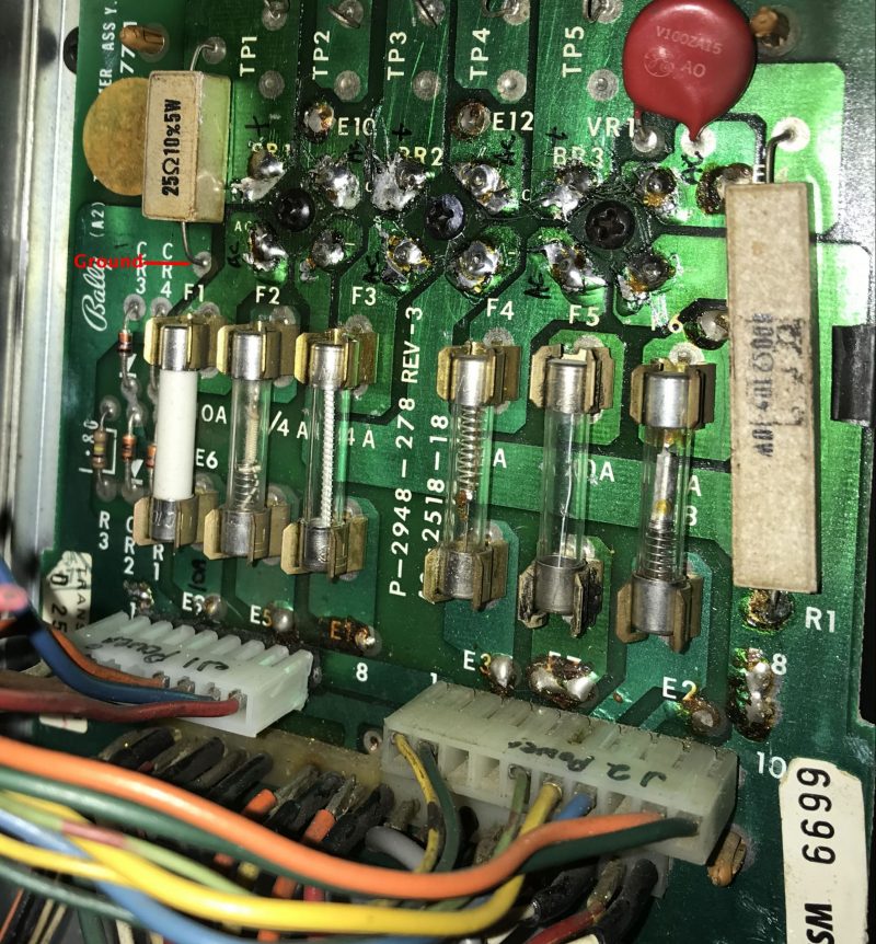
The photo shown of the -18 board shows a number of slow blow fuses. My parts list shows F6 as the only slow blow. thoughts? TIA
Interesting observation. We have no idea where that image came from, but we always recommend checking the manual, the PCB and the backbox for a list of the proper fuses.
It looks like F2 and F6 should only be SB.
We are constantly finding pins with the wrong fuses in them.
We will search out a photo with the proper fuses in place and replace that photo.
Thanks.
In your directions for how to test a -54 Rectifier, it appears there’s an error. You direct someone to have only J6 connected. In truth, J5 needs to be connected, too, or else there will be missing/erroneous voltages.
Thank you! You are exactly correct. Without J5 connected, there will be no GI AC, high voltage for the displays nor the 43+ V DC for the solenoids. We have made the correction.
We appreciate your feedback.
The HomePinballRepair Team
Hi, I have a Bally Paragon that Im trying to bring back to life. Its previous owner was a hack. Im working on the rectifier board where he had some wires reversed. The new rectifier board has 1 more pin on the J1 than the old connector. I picked up a new connector with 9 pins to match the new board. Is there a wiring diagram/ pic as to where the wires/pins connect to on the new board?
Thank you
Do you have a copy of the manual? It is convoluted to follow, but the connections are listed there. It is one of the yellow sheets in the original manual. Unfortunately, the connections are not listed by color – but you are lucky in that J1 has only 6 wires.
J1 goes to the playfield. When you look at the manual (we cannot post a photo here for some sad reason) you will then need to trace where each of the wires goes to the playfield. One will be to the solenoids, one to switched lamps, but four will go to the GI bulbs. That is AC so it is not terribly critical which one goes to where. But there will be two pair. One of each pair must go to ‘Gen. Ill. Ret’ and the other one from that pair must go to ‘Gen. Ill. Buss.’. Otherwise the GIs will not light.
The original is an 8 pin plug. We are thinking that this aftermarket board might have 9 pins because some games used the same board but had one more connector – not sure.
But the important part is to install the key (or polarizing) plug into position #4. We know someone who re-did the plugs and left the key out. The plugs were put in either off by a pin or in the wrong position and the game burst into flames.