B. Data East / Sega versions 1, 2, 3, 3B
1) Board Locations
2) Main Power supply
– Power Supply Board
– Solenoid and Switched Lamps
3) PPB Power Supply
4) Sound Board Power
C. Solid State Troubleshooting
1) Early Bally / Stern
– Voltages Required
– Solenoids
2) WPC Bally / Williams
3) Williams 11
4) Williams 3 – 7
5) DE – Sega – Stern
– DE / Sega V3 & 3B
– Sega / Stern Whitestar
D. EM
This covers Data East and Sega pinball machines known as System 1, System 2, System 3 and System 3B. These machines were sold under the Data East and Sega names from 1990 to about 1995.
There are several similarities between these systems and Williams System 11, although Data East and Sega would deny that. But those who are familiar with Williams System 11 may feel right at home here.
There are differences between the power supplies with different part numbers and, sometimes there are revisions within one part number. We tried to take into account those differences, but it is important to note that these procedures may vary between boards.
This section covers checking to insure the voltages are present. It also covers troubleshooting non-working solenoids.
Prior to starting, check the tools required and cautions.
Understanding the Layout
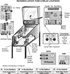
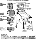
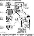
All version have the following circuit boards:
* CPU Board
* Sound Board
* Power Supply Board
* PPB Board (the first two, Laser War and Secret Service, have only a 50 V flipper supply)
* Flipper Control Board (located in the cabinet)
There are also separate bridge rectifiers and capacitors located off the boards in the backbox.
Some may have a shaker motor board in the cabinet.
Testing the Power Supply (Main Board)
What can go wrong
1) Fuse blown. Common. Can be a bad fuse. Or another issue like a blown rectifier.
2) Bad fuse clips. Data East fuse holders fail regularly.
3) Bridge rectifiers fail. Common. Will be checked with voltage testing.
4) Voltage regulator fails. Failed C2 and / or C3 can result in low 5V. A failed IC1 can result in the full 12V going to the CPU. If 5V voltage is good, then the regulator is good.
5) Connectors burned or fail. Common, especially the GI plugs. Visually look for burned connectors and replace.
6) Board failure. Burned traces. Bad connector pins. Common. Will check visually.
7) Main +18 V capacitor gets old and fails. C1. C2, C3 or C7 fail.
8) Main fuse is blown. Unplug the power, remove and check the fuse in the can in the cabinet.
9) Transformer fails. Extremely unlikely unless wrong fuse is used. Will be checked under voltages.
Checking Voltages
The DE/Sega system 3 has two different power supply boards: “PS Power Supply” and “PPB Board”, plus two rectifiers and a capacitor located by themselves in the backbox. Each needs to checked separately. Additionally, the sound board has two voltage regulators. And the Solid State Flipper Board has a low voltage power supply which provides the ‘hold’ power for the flippers.
Power Supply Board
The power supply board creates the +12, -12, +5 VDC supplies that are critical to proper operation of the game. It also creates the very high and dangerous high voltages used for the displays.
| Note: If there is any chance the power supply is malfunctioning, it is better to isolate the power supply so that it does not damage the other boards. For most models, that means unplugging everything except CN1 and CN2 of the power supply board. If the +5 rises too high, it can blow the chips on other boards. |
Power Supply Versions
There were eight power supply versions used on Data East / Sega 1, 2, 3 and 3B systems. They can be broken down into three types:
Alpha Numeric Power Supply 520-5000-00
Used in Data East System 1, 2 and early System 3. This includes Laser War, Secret Service, Torpedo Alley, Time Machine, Playboy 35th, Time Machine, Torpedo Alley, Secret Service, ABC Monday Night Football, Back to the Future, Phantom of the Opera, Robo Cop, and The Simpsons.
DMD (128 x 16) 520-5047-00
Batman (Data East), Checkpoint, Hook, Star Trek 25th Anniversary, Teenage Mutant Ninja Turtles.
DMD (128 x 32, ‘Normal’ Size) 520-5047-01 & 520-5047-02
Guns N Roses, Jurassic Park, Last Action Hero, Lethal Weapon 3, Rocky & Bullwinkle, Star Wars, Tales From the Crypt, Tommy, Wacky Gator, WWF Royal Rumble. This power supply has a more robust high voltage supply for the larger display. Note that -02 Rev B can be used in -01 games, but -01 cannot be used in -02 games. Each board has a Rev A and a Rev B, but the differences are not important for our troubleshooting here.
DMD (128 x 64) 520-5047-03

Batman Forever, Baywatch, Mary Shelly’s Frankenstein, Maverick. There is no high voltage power supply for the larger DMD on this board. The power is generated by two separate boards. There is a separate +5 V DC and the high voltage is not generated on the Power Supply Board.
All versions have nearly identical +5, +12 and -12 volt DC circuits.
Note: If you have replaced the original displays with LED or LCD, then the high voltage section should be disabled by removing the proper fuse. On DMD power supply boards, these are F4 and F7. On Alpha Numeric displays, this is F3. Place a label stating that this fuse should not be replaced.
F7 on DMD displays just removes the center tap from the high voltage section of the transformer. There will still be high voltage present CN1-4 to CN1-7.
| Note: A common problem with these versions of power supplies are the fuse holders. They frequently fail / lose their ‘spring’. Inspect and replace when necessary. |
+/-12 and +5 Power Supply
In order to check voltages accurately, it is important to use the ground on the board under test.
F1 and F2 protect this supply. If either is blown, the machine will not operate.
1) Turn the machine off.
2) Connect the black lead to ground TP2.
3) Connect the red lead to TP1. Turn the machine on. Read 5.0 V DC (4.9 – 5.2, 4.8 is too low).
4) Connect the red lead to TP3. Read +12 V DC. This is unregulated, so it can be a bit low or high (10.5 to 13.5 or so).
5) +5V DC – 3J6 pins 7, 8, 9 or 10. +4.9 – 5.2V DC is OK.
+12V DC – Either side of F5 (this is unregulated so about 10 – 14V DC is OK).
Troubleshooting the +/-12 and 5 Voltages

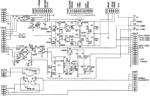
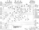
Note that the DE/Sega circuit is nearly identical to the Williams System 11 circuit. Williams was nice enough to record the proper voltages on the circuit diagram which we have included here. If there are issues with the +5, it is helpful to measure and compare those voltages. Note: High voltages are nearby on this circuit board.
* If the +12 or -12 voltages are low, it can be a bad (open) bridge rectifier at DB1. A shorted bridge will blow a fuse. Test it using the diode tester. Also check for bad or cracked solder joints at this bridge rectifier on the board. When performing the diode test, disconnect the transformer by unplugging CN1.
* Inspect C4. If it is leaking or bulging, replace it. Later games replaced C4 with four 4700 MFD at C11 to C14. Those can also fail. Inspect for leakage or bulging. If one is bad, replace all four.
If the +12 V is OK, the problem is with the 5 V regulator.
The 5V supply is controlled by transistor TR5 and IC1. If the 5V reads about 4.5V or so:
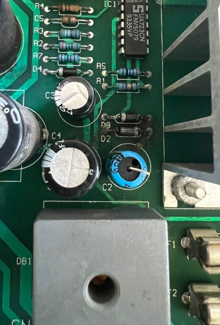
* Inspect / test C2, C3 and C7. A failed C2 or C3 will result in low 5V DC. C7 seems to be especially prone to leaking. If C3 fails, the +5V DC is likely to be half.
* C5 and C6 are a less likely to fail but should be inspected / tested.
If the 5V reads high, perhaps as high as 12V, then IC1 has likely failed (and catastrophic damage may have occurred to the CPU).
Look for a leaking or deformed capacitor – although if not leaking / deformed, it does not mean it is good. Can also check with a capacitance meter. Some voltmeters have capacitance testing built in.
Check the voltages on IC1:
| PIN number(s) | V DC |
| 2, 3, 4, 5 | 5V |
| 6 | 7.1V |
| 7 | 0 (ground) |
| 10 | 6.47V |
| 11 & 12 | 26.7 |
* If pins 12/11 are low on IC1, it is likely C2 or C3. This is a voltage doubler.
* If pin 10 of IC1 is OK, then it maybe TR5. If the +5 is still missing, test the transistor TR5.
* If one side of R6 has +5, but the other side is low, check C7. Less likely is a C6 failure.
* If the transistor is good, check pins 5, 4, & 3. If pin 5 is +5 and pins 4 or 3 are not, it is likely IC1.
If the -12 V is low or missing:
* Inspect C1. If it is leaking or bulging, replace it.
* Check the bridge rectifier (see above).
High Voltages – Display
High Voltages (see cautions). Note that there are not any test points for the high voltage supplies. It may be easier to measure these voltages at the plug on the display. Note that these voltages are dangerously high – only qualified tech should attempt.
Alpha Numeric Displays
Alpha Numeric Display Measurements (all V DC):

Measured on the Display Board at CN4
#1 = -100
#3 = +100
#5 = Ground
#6 = +5
Measured on the Power Supply Board at CN5
#1 = Ground
#3 = -100
#4 = +100
#6 = 5
DMD Displays (Except the Largest 128 x 64)

DMD Pin Measurements (for all DMD games, all V DC):
#1 = – 110
#2 = -98
#3 = key, N/A
#4&5 = Ground (read nearly zero vs. Power Driver Board, but may get a very low reading)
#6 = +5 (4.9 – 5.2)
#7 = +12
#8 = +68
Power Supply Measurements (CN5)

#1 = Ground
#2 = -98
#3 = -110
#4 = +68
#5 = +12
#6 = +5
Troubleshooting the High Voltages
All these high voltage circuits used a similar design. The larger displays used more robust (higher current) transistors. In all cases, if either the plus (+) or minus (-) voltage is wrong or missing, turn off the power and check the resistance of the resistors. If off, you could try replacing them and see what happens. Otherwise, all of the major components in that section should be replaced. Both transistors (each half has two), and all of the diodes. The zener diodes are especially prone to fail. Note that the (+) side (+68) and the (-) side (-110 & -98) are separate. If only one side is out, it might be necessary to replace only the components in that side.
Great Plains Electronics used to sell rebuild kits for these supplies, but, as of 2022, no longer do. However, their parts list serve as a great guide. Here is a checklist for Williams high voltage power supplies from GPE. It can be used as a rebuild guide, but be careful to compare the parts listed to those on your power supply board and substitute as needed. The alpha numeric power supplies used very different components than the DMD high voltage supplies. And the smaller DMD games had different components from the larger DMD. And the 128 x 64 (largest) DMDs were altogether different.
Only the DMD supplies have a +12 volt supply. That design is fairly simple. Check insure that there is voltage coming into VR1. Use fuse F4 as a test point (check both sides). If that checks good, but not at the output, then VR1 has likely failed. The two small electrolytic capacitors C15 and C14 can also fail, so check them for leakage, damage, or if they are shorted and replace as needed. If you have a capacitance tester, now is the time to use it.
If there are problems with the high voltage power supply, the best options are to either 1) buy a new aftermarket board, or 2) replace the plasma displays with modern LED displays that do not require the high voltage. We prefer replacing the displays since the original ones are nearing the end of their useful life. If you decide to remove the original displays for LED, be sure to remove the fuse(s) to this high voltage section.
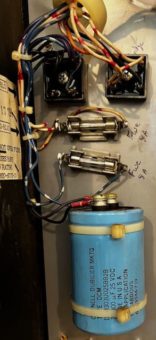
Off the Boards Backbox Voltages
– Controlled Lamps & Solenoids
Note: As far as we know, all DE and Sega System 1, 2, 3 & 3B pins have two fuses, one before each of these bridge rectifiers. They should be located near those rectifiers. If your’s does not have them, install a fuse and holder on the AC side of each rectifier and let us know.
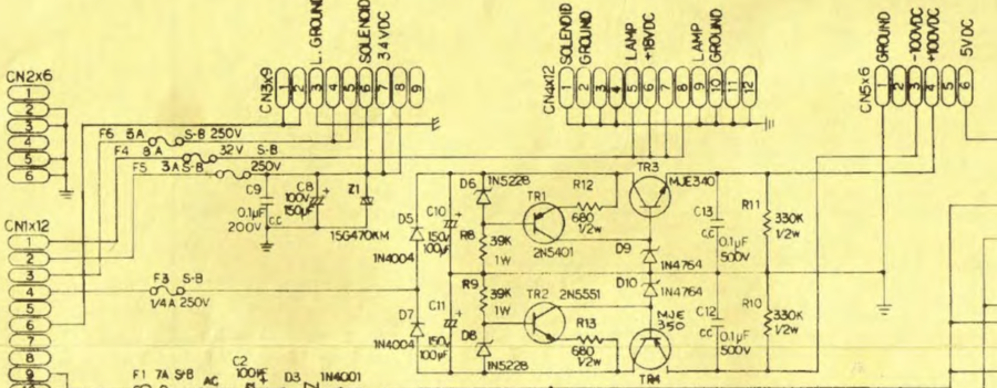
These are two rectifiers located by themselves in the backbox. These supply the +18 V DC to the power supply board and +34 VDC for some of the solenoids (not the flippers). Those power supplies consist of two fuses, both 8A Slo Blo (slow blow), two rectifiers and one large capacitor.
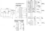
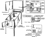
The first drawing shows the main power transformer and the AC outputs. The 6 V AC powers the GI lamps. The rest of the outputs go to the various power supplies and are converted to DC.
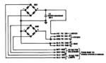
The first of these power supplies is in the second picture – the two bridge rectifiers. BR1 along with C1 converts the 13 V AC to 18 V DC for the switched lamps. The large capacitor removes the ripple (noise) output from the bridge.
BR2 converts the 25 V AC to 34 V DC for some of the solenoids.
Testing
Turn off the power.
Note: These voltages are not regulated, so some variation is expected and is OK.
1) Connect the black lead of your voltmeter to the (-) minus of C1 and the red to the (+) plus side of C1. Turn back on the power. This voltage should be about 18 V DC. Switch the meter to AC and check. The voltage should be very low, 0.2 V AC or less is typical.
2) Leave the black lead on the (-) minus side of C1. Connect the red side to either the (+) output of BR2 (orange wires) or to CN1-2 or CN1-3 . This value should be about 34 V DC. Do not check for AC since there is not a capacitor here (although there is a small one on the power supply board).
Troubleshooting these Voltages
If the voltages are low, it is usually a bad (open) bridge rectifier. It is important to remove the bridge from the transformer when performing this test. The easiest way is to simply remove the fuse on the AC side of the rectifier. Also remove CN1 and CN2 from the Power Supply Board.
If either of those 8A fuses blow, then it is likely that the rectifier needs to be replaced. To test, turn off the machine, remove the 8A fuse, unplug CN1 on the Power Supply board, then test the rectifier.
The large capacitor is for the switched playfield lamps. That usually does not fail by shorting. It usually loses capacitance which would increase the AC to the lamps. To insure that it is not shorted, check its resistance.
The output of these supplies then pass through that main power supply board. The board passes the DC voltages through fuses and then back out. There is almost nothing that can go wrong there, other than a bad fuse holder or a bad connector.
If the lamp fuse on the power supply board blows, it could be a shorted bulb, shorted socket or a wiring issue. If the fuse for the this voltage solenoid blows, it could be a locked on solenoid, shorted coil or diode.
The solenoid voltage does include two small capacitors on the power supply board. C8 is a 150 uF electrolytic cap that should be inspected. If it appears damaged, has leaked, or is otherwise deformed, replace it.
Oddly, DE/Sega included a Z1 on the board that appears to be a Zener diode but it is not. As best we can tell, it is Metal Oxide Varistor (MOV) also sometimes called a Varistor. If it is defective – there isn’t an easy way to test it other than looking for visual damage. It could be removed and not replaced as similar designs do not have this component. But it is there to prevent too high of voltage going out the computer boards and damaging them. It may be a good idea to replace it with a 47 Volt MOV V47ZT1.
Testing the PBB Power Supply
The PBB supply serves several functions, from providing fuses for the GI lamps, switching between solenoids and flashers, high power drivers for certain solenoids and a relay to turn on and off solenoids.
But the function we are looking at here is the flipper power supply. The flippers use 50 V DC and it is generated here. 48 VAC comes in from the transformer, BR1 is the bridge, located on this board, that converts it to 50 V DC. There is a small electrolytic cap C1 which is 100 uF 250 V. There are a few differences in the connectors between generations of boards, but, other than that, the circuit is pretty much the same.
Measuring the Voltage
There are not any test points on this board. The voltage can be measured at J7 or at the flipper coils.
Note that the 50 V DC may measure higher than 50, perhaps as high as 70 V DC. That is because the power is not under load and capacitor C1.
Troubleshooting
Not much can go wrong other than the bridge and C1. If the bridge rectifier opens up, then the voltage will drop. If it shorts, the fuse will blow. Disconnect the bridge and test it using the diode tester. Be sure to disconnect the bridge from the transformer when performing this test. Either remove J4 or remove the 5A SB fuse going to this bridge.
If C1 leaks, it can cause the flippers to be weak or the fuse to blow. Connectors could burn or be damaged, but this is more likely with GI connectors.
Testing the Sound Board Power Supply
Data East had high quality (usually) stereo sound boards. Sega continued to use similar designs. It was only when Stern took over manufacturing from Sega that the sound boards seemed to take a step backwards into mono, regrettably, including the Lord of the Rings pinball machine.
|
Disclaimer: There are two major generations of sound boards involved. The first only generated the -5V DC. The other voltages are from the main power supply. There are other differences between the boards. Most of those involve the logic portion, but there are differences in the amplifier section also. We did our best to find a way to confirm that the power supplies are working, but we likely missed something. Please let us know so we can fix this. |
Differences Between Sound Boards
DE System 1, 2 & 3 (early) – Laser War was the only DE System 1 and it used +5 and +12 directly from the main power supply. The +12 was used on the stereo amps.
This same power supply is used on sound boards in DE System 2 Time Machine, Secret Service, Monday Night Football, Playboy 35th, Teenage Mutant, etc. System 3 started out with the same power supply design in Back To The Future, The Simpsons,
The only test for +5 and +12V DC is to determine that the connections, including ground, are good.
However the -5V DC is generated on the sound board and that needs to be tested.

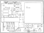
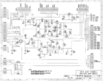
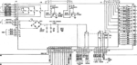
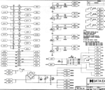
DE System 3 (later) & 3B – Later Data East System 3 games, starting sometime around 1991 (Star Trek, Hook, etc.), the sound board also generated the +5V & -5V DC power for pre-amplifiers LM833N. These boards continued to use the main power supply +5V DC for the logic and the +12V DC for the output amplifiers. There are a number of different generations of these boards, but the power supplies seem to be the same. This picture is for the 520-5050-00 sound board. Other boards have the same power supplies with some differences. These differences can make voltage measurements difficult.
These power supplies are labelled as +5A and -5A to differentiate from the +5 from the main power supply board.
Measuring the Voltages
The first step is to determine if you have a sound board with a power supply that looks like the first image or the second one. Pull out your schematic and then confirm that it is the right one for your sound board.
There are no test points on these boards, so finding a spot to measure the voltage can be a challenge.
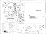
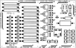
DE System 1, 2 & 3 (early)Board 520-5002-x
These boards (first image in this section above) only generated a -5V (from the -12V input).
The other voltages, +5 and +12V DC, come from the main power supply board. It is also important to determine that the +5, the +12 and ground connections are good.
Confirming the +12, +5V DC and Ground are Good
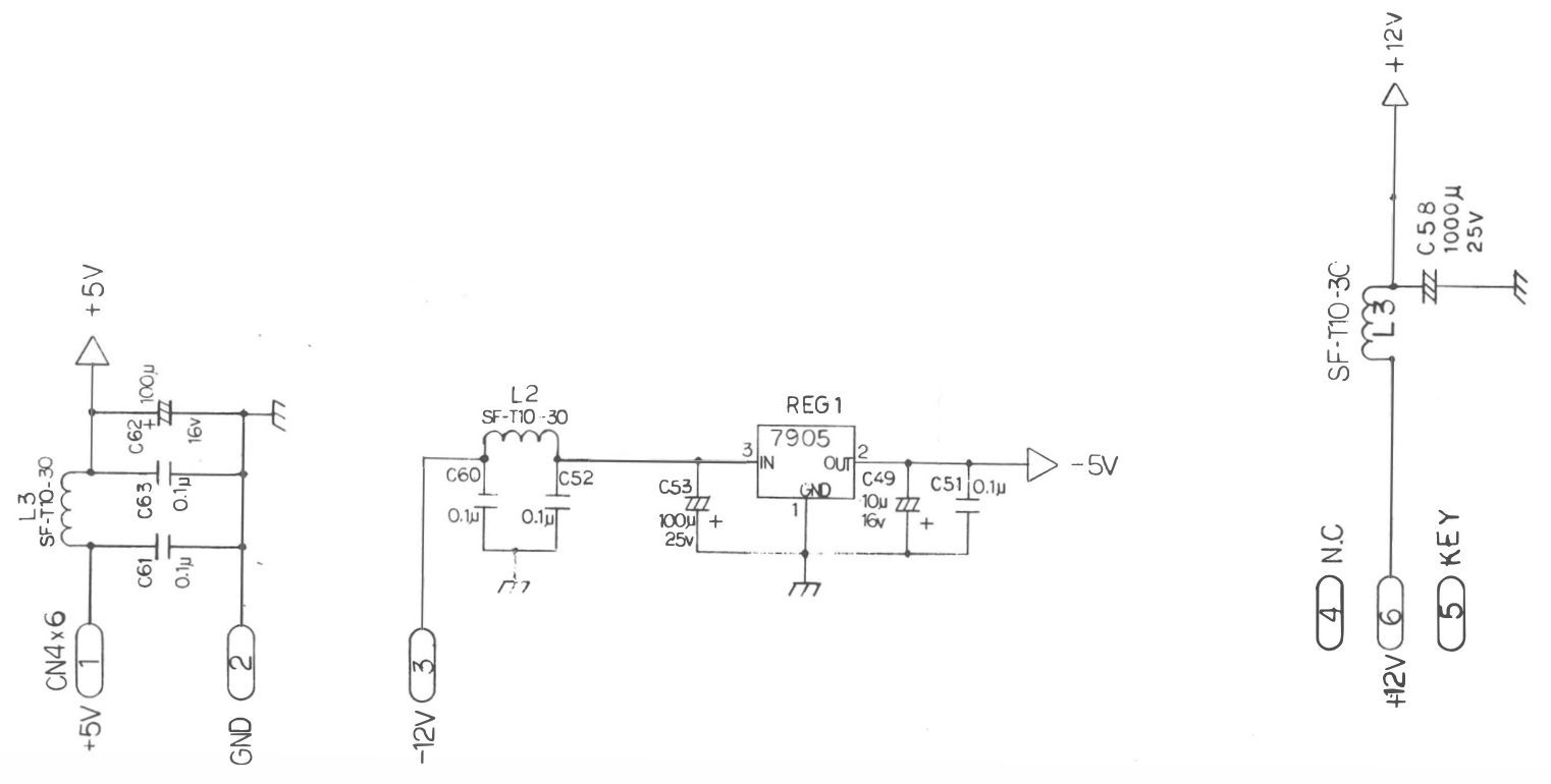
Confirming the +12V DC on these early models seems to change from game to game, so be certain to check your manual and hope that it is accurate. Example: Laser War schematic has two L3’s!
The +12V DC can be confirmed by measuring across C56 or C59 on many games. One side is ground and the other side is +12V DC.
However, first generation DE Sound Boards System 1 (Laser War) did not have a C56 or C59 on the +12V DC. Later models such as Secret Service have C61 and C57, so this gets messy.
Alternately, either side of L1 will yield +12V DC (although on Secret Service, that maybe L3). Use a corner screw as ground, but this is not a reliable way to confirm the ground on this board.
The +5V DC can be confirmed by measuring across C63 (or C61 on some models). One side is ground and the other side is +5V DC.
Alternately, either side of L3 will yield +5V DC. Use a corner screw as ground, but this is not a reliable way to confirm the ground on this board.
Measuring the -5
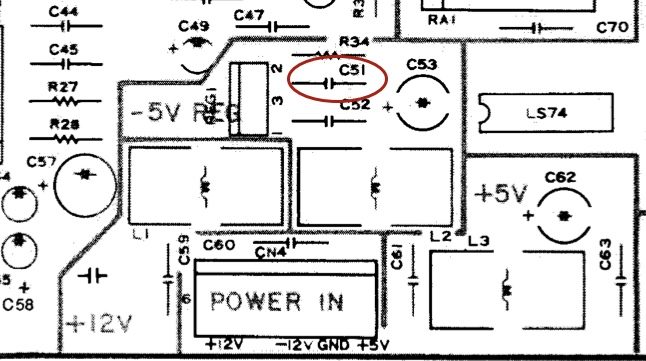
Locate C51. One lead should be -5V DC and the other should be ground.
If the -5V is missing, then check the voltage across C52 or C60 which should be -12V DC. C52 is located immediately below C51, while C60 is just above the Power In plug CN4 (on most games).
What can go wrong
1) Electrolytic caps fail. Leaking caps can cause board damage.
2) Reg 1, the -5 voltage regulator, fails.
3) Header pins solder points crack / fail, power plug fails, IDC pin to the wire fails, etc.
If either the +5V DC, -12V DC or the +12V DC are bad, check them at the main power supply board. If they are good their, you either have cracked solder at the header pins (remove the both boards and inspect), or a bad wire / plug connection.
If the -5V is missing, but the -12V DC is good then suspect the 7905 voltage regulator. But check continuity and look for cracked solder joints, plus ‘buzz out’ the traces with your voltmeter prior to replacing.
Also insure that the ground is good.
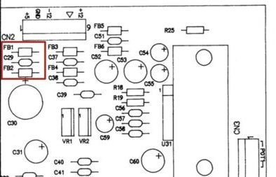
DE System 3 (later) & 3B Board
Confirming the +12, +5V DC and Ground are Good
Note: There are two +5 voltages. One is from the main power supply board while the other, designated as ‘5A’ is derived from the +12V DC.
Measuring the +5
This is the +5 generated from the main power supply board. Touch your DVM lead, either wire from FB1 or FB2, and connect the other end to ground. Any screw on any of the corners is grounded, but one of the wires of C29 (usually on the left side closest to C30) is better to use as ground. Compare this value to that measured at TP1 on the main power supply board. This should be pretty close with less than 0.1V DC difference.
If greater than 0.1V DC, try unplugging and plugging back in CN2 on the sound board. If this changes the value, check the back of the header pins for cracked solder joints, the condition of the pins (for corrosion) and/or consider replacing the plug with Trifurcon crimp connectors.
By measuring the +5 vs. ground, if the +5 is good, then the ground is good.
The +12 is used to generate the +5A, so if the +5A is good (next step) then the +12 is good.
Measuring the +5A

The +5A is generated on this board and is a different +5V DC supply from that checked above. This voltage is generated from the +12V DC supplied by the main power supply. If the +5A is good, the +12 has to also be OK.
Given that there are some differences between generations of these boards, finding a point to measure the +5A voltage is not easy. In (we think) all versions, one lead of C47 should be a good place. The other lead should be ground.
Also, U30 pin 8 should read +5V DC.
Measuring the -5A

In (we think) all versions of later generation sound boards, one lead of C40 and C49 should read -5V. The other lead should be ground.
U30 pin 4 should also read -5V DC.
What can go wrong
1) Electrolytic caps fail. Leaking caps can cause board damage.
2) VR1, the -5 voltage regulator fails.
3) VR2, the +5 voltage regulator fails.
4) Header pins solder points crack / fail, power plug fails, IDC pin to the wire fails, etc.
If the +5V or +12V DC are bad, check them at the main power supply board. If they are good their, you either have cracked solder at the header pins (remove the both boards and inspect), or a bad wire / plug connection.
If the +5A is bad but the +12V DC is good, suspect VR2. But check continuity and look for cracked solder joints, plus ‘buzz out’ the traces with your voltmeter prior to replacing.
If the +12V DC is good then the ground is good.
If the -5A is bad but the -12V DC is good, then suspect VR1. But check continuity and look for cracked solder joints, plus ‘buzz out’ the traces with your voltmeter prior to replacing.
If the -12V DC is good then the ground is good.
External Links
Data East Power Supply Corrosion Repair – Troubleshooting a leaking capacitor.
Copyright 2022 – 2024, all rights reserved.
Comments
Comments, including suggestions, improvements, errors, etc. are welcome (see below).
If you have a specific question about your game that does not directly apply to this page, please see our FAQ section.