Fix Those Flicking Pinball Lamp Sockets
If you have pinball lamp sockets that flicker, dim and sometimes don’t work, this step-by-step procedure will fix them for you.
Two different Types Of Lamps
Up until recently, most pinball machines use two different types of sockets:
- Those round types for #44 or #47 bulbs. These are known as miniature bayonet bulbs.
- #555 miniature wedge shape.

Note that there are different size bulbs that use bayonet or wedge shapes. These can be for flashers or specialty bulbs. The fixes here also generally apply to them.
Also, new games that have LEDs may use small circuit boards or a different type of connector that is not addressed here and generally do not have these types of problems.
Note: Click on the photo for a larger image.
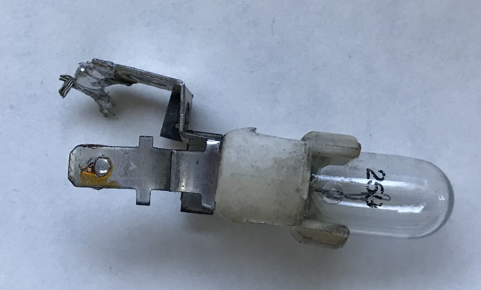
The Diode

All SS lamps that are controlled by the computer (except early Bally & Stern) are part of a lamp matrix and have a diode. If the lamp never lights, it could be a bad diode that is open.
To test, remove the bulb, then put your DVM in the diode test mode and connect the leads across the diode. One direction will read high and the other direction will read low if it is good. If both directions read high, it is defective – replace it.
If both directions read nearly zero, the lamp will light, but so will other lamps when only one lamp should light. Also replace the diode.

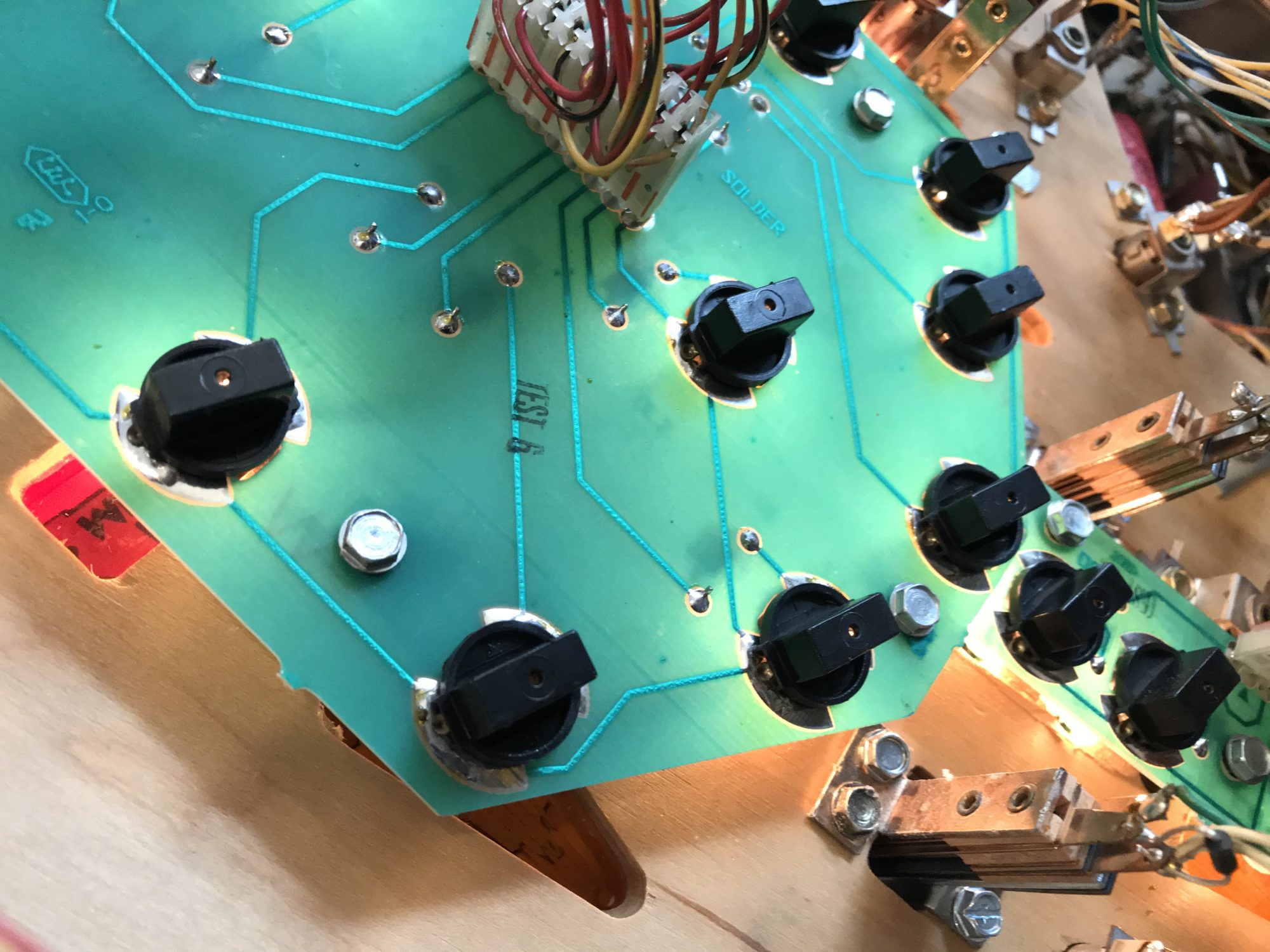
Note that it is crucial that the band of the diode be in the same direction as it was originally. In the above photos, the wire is connected to the lower tab. The band of the diode goes towards the tab with the wire.
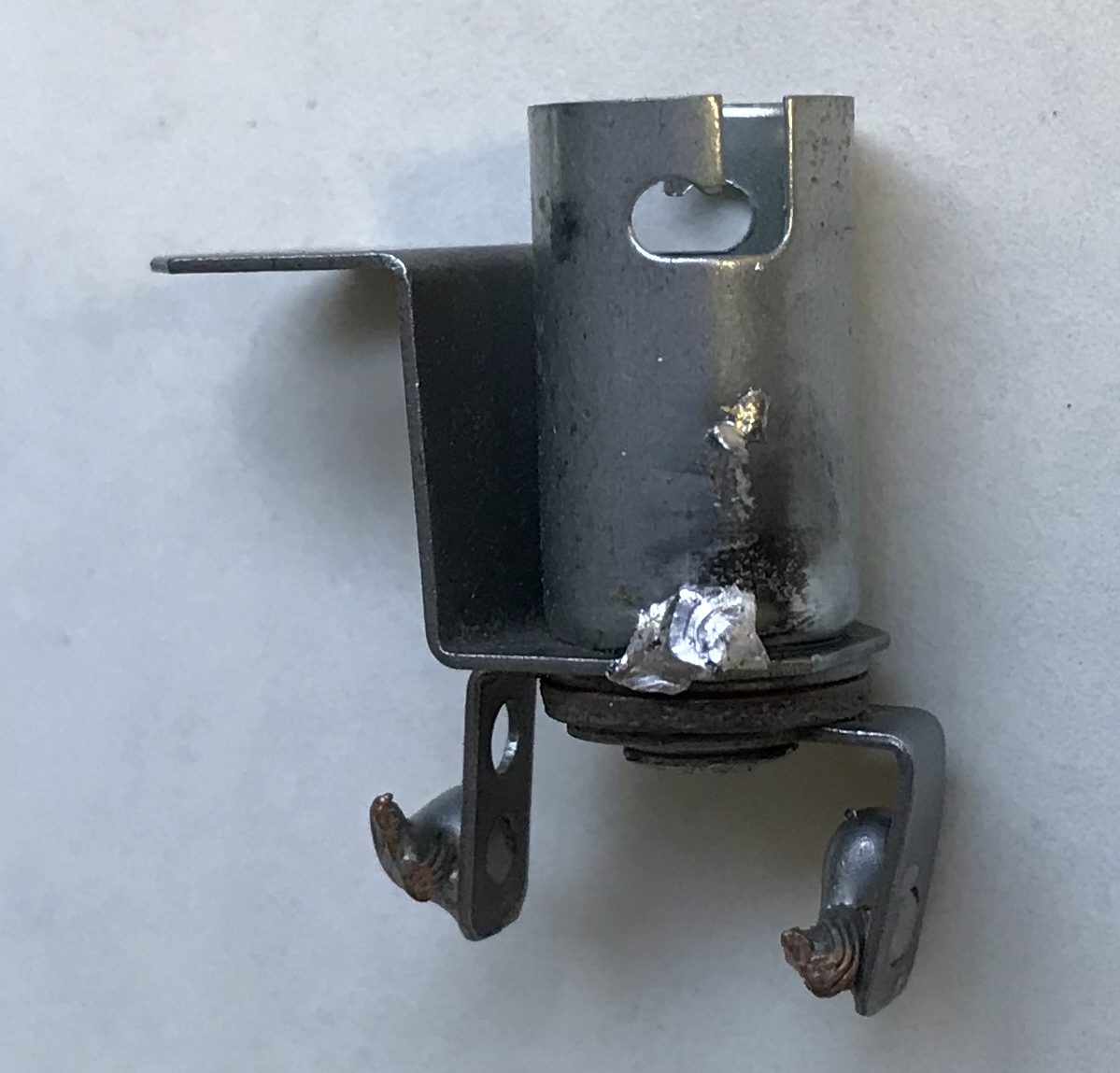
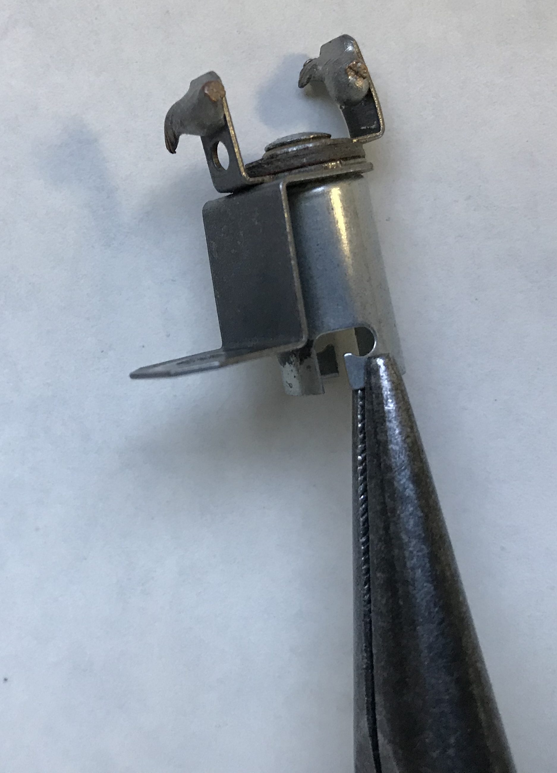
#44 / #47 Bayonet Bulb Socket

Most of these sockets can be restored. As they age, corrosion occurs and corrosion (oxidation) makes a great resistor and reduces the brightness of the bulbs. Plus, where two metal parts meet, electrical contact is sometimes lost.
Both of these points in the first photo can be fixed with solder, or solder and wire.
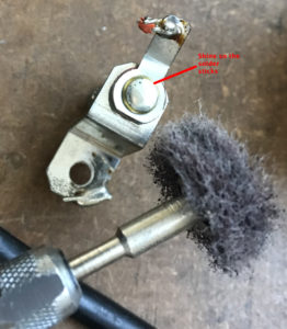
In the second image, cleaning and a little mechanical adjustment will do the trick.
At points 1) and 2), the important first step is to shine them up and remove any remaining corrosion (oxidation) so that the solder will stick. That is accomplished using an abrasive tool such as a wire brush, stone, or carbon steel brush. All of these are available as Dremel tools which makes this a fast and simple procedure.
Some Differences in Construction
On the bottom of the bulb socket (#2 above), there might be an ‘open flange’ with a hole in the middle of it. Or it might be a closed tab or button. It does not matter as the fix is the same.
Also, some the sockets might have a tab connected to the barrel (#3 above), or that barrel might not have a tab and the wire is connected to the bracket (#2 picture above). It does not matter as this fix is also the same.
Some sockets might have a third tab. The wire comes into that third tab, then a diode is connected to bottom tab (#2 picture above). This is a crucial difference as the diode must be left in the circuit. The ‘fix’ wire must be made from the diode non-banded side (not the wire / diode banded side) to the lamp button.
Soldering The Weak Points

Pull out your Dremel and one of the abrasive tools. We prefer the wire brush, but the carbon steel brush 443-02 will work too. Wearing safety glasses, carefully shine up spots on both the tube that holds the bulb and where the tab comes in.
If those spots are not perfectly clean, the solder will not stick.
Next, heat up your soldering iron. If your iron is adjustable, turn it up high. We use 700 F (370 C) but it could be hotter. The solder will not stick to the bulb socket unless it is hot enough.
Pick a shiny spot on the bulb tube and heat it. After it gets hot, apply solder until it flows on the tube. Continue to heat where the tab comes into make a solder bridge. It likely will not look neat, but we don’t care. The point is to make certain that the electricity flows from the tab to the tube that holds the bulb.
Test the solder spot with a screwdriver and make certain it sticks. It may take practice to make this a good solder connection.
Next, we are going to fix that pesky spot where the electricity comes into the point at the base of the bulb. Once again, we have to use our abrasive tool to shine up the tab in the center.
Once it is shined up, pull out your very hot soldering iron and apply a tab of solder on that tab.
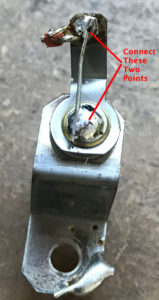 Find a short piece of thin stiff wire. We keep leads from resistors specifically for this purpose. Remove the bulb. Solder that short length to the spot of solder from the previous step. Solder the other end to the tab where the wire comes in. After the socket has cooled, replace the bulb. Using a stiff wire here has the added benefit of increasing the ‘spring’ pressure on the base of the bulb.
It is possible to use stranded wire for this connection, but that will not increase the pressure on the bulb.
Some move the wire connection from the tab to the base of the bulb, but this is not recommenced.
At this point, you have taken care of the weakest points on a bulb socket.
Clean The Other Bulb Contact Points

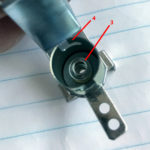
There are two areas of the interior of the bulb that needs to be taken care of (#3 & #4 in the photo). They are the point where the bottom of the bulb makes contact. And the sides that connect to the tube of the bulb. Both of these are going to be fixes using an abrasive only – no soldering.
There are two ways to do this: 1) Use a bulb socket cleaning stick, available through parts suppliers such as Marco and The Pinball Resource. 2) Or use one of our abrasive tools connected to a Dremel.

The bulb socket cleaning stick is the easiest. It can be done quickly at the pinball machine without taking much apart. But we have gotten mixed results from using these. Try bulb cleaning stick first. If it fixes it up, great. If not, pull out the Dremel.
For the Dremel, use a small stone tool or the carbon steel brush and shine up that contact point. A quick low speed spin with the center contact point shines it up and removes the corrosion. While at it, also spin carefully around the inside of the tube.
The tube of the socket has two ‘ears’ where the bulb locks into place. Those ‘ears’ can be easily bent using needle-nose pliers. It is easy to bend them too far. Just a small bend inwards is all that is needed. After adjustment, insert a bulb. The bulb should be snug. If it is too difficult to insert the bulb, adjust with the pliers.
Pop Bumper Lamps
Pop bumper lamps that use #44/47 bayonet bulbs have terrible sockets. If you are determined to keep them, use the dremel tool and shine up the sides and the bottom contact.
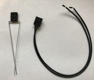
For reliability, replace them with a #555 style socket for pop bumpers. The straight wire type can be used, but it is easier to use a flexible wire. The downside of the flexible wire socket is that it stands higher and the bulb may not fit in with the pop bumper cover on. If using LEDs, use the shorter bulbs that are readily available.
#555 Miniature Wedge shape
In the early to mid-1980’s, some games converted the conventional bayonet bulbs to wedge shape. Unfortunately, many of those sockets were terrible and not a whole lot can be done to fix them.
For example, if your #555 lamps under the playfield in your Eight Ball Deluxe are giving you fits, the best to do is replace them with bayonet base #44/47.
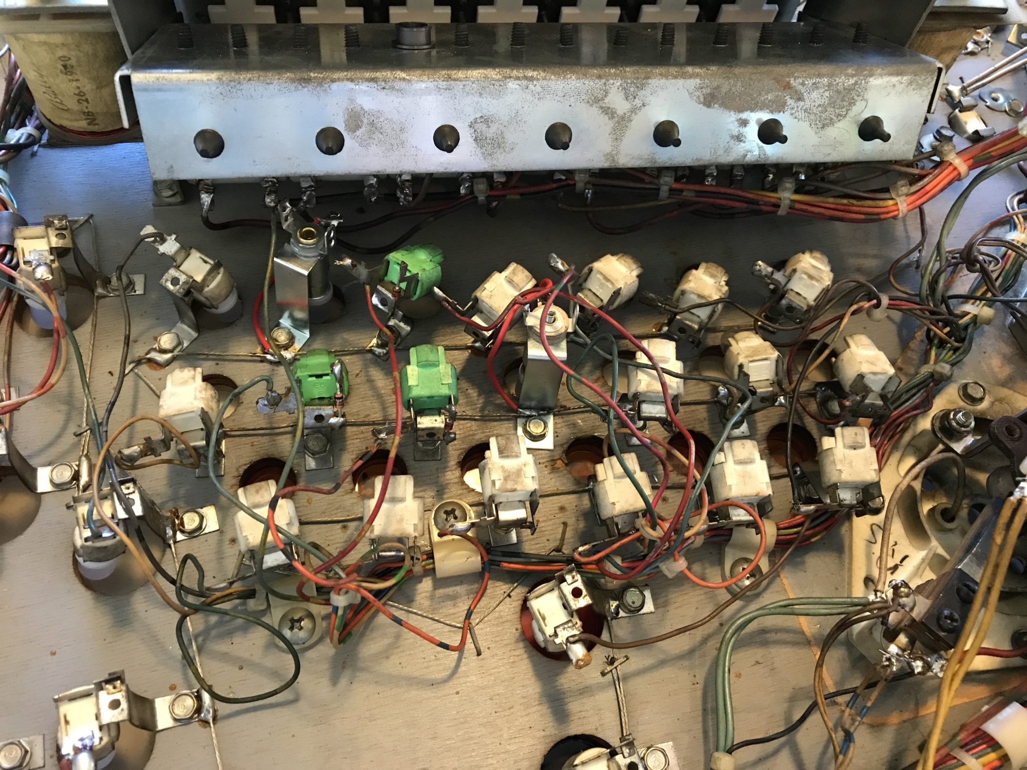
#555 sockets are frequently used on lamp circuit boards in later games. Sometimes the lamps will flicker, dim or not light at all. They are easy to fix.
I usually remove the lamp boards from the playfield. Turn off the pin, unplug the connector and remove the few screws that hold the board to the playfield. The cause of the problem is almost always the plug pins or the contact points where the lamp holder screws in.
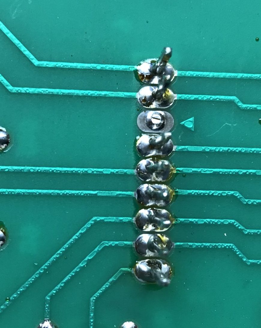 Inspect both sides where the plug connects to the board. On larger board, a bad solder connection could affect two or more lamps. If necessary, reheat and add new solder so that it flows around the pin. Be sure to heat the pin so that the solder sticks to it.

The most common problem affects only one lamp. Usually, the bulb holder makes a ‘dimple’ of sorts on the contact area. We find the quickest fix is to heat up the solder on the board. Adding a small amount will make it melt easier.
Finally, if one bulb does not light at all, it could be an open diode. Or someone replaced a diode and put it in backwards. Test as indicated near the beginning of this page.
If more than one lamp lights when only one should, a diode maybe shorted.
Comments
Comments, including suggestions, improvements, errors, etc. are welcome (see below).
If you have a specific question about your game that does not directly apply to fixing lamps, please see our FAQ section.
I just fixed a bunch of lamps on two Williams 90’s games and found over the years that the chief problem (more than even bulbs burning out, or diodes going bad, etc) are the the little gold nipple tabs on each side of the lamp socket making good contact with the lamp circuit board. They’re springy so I simply bend the tabs up on each side and that fixes the problem 95% of the time.
Great comment Carl. We do that too and should have mentioned it in the article. Between re-flowing the solder in the contact area on the board, bending down those tabs just a little bit (we try to clean the oxide off, too, but that is tough), and reflowing the header pins, all the problems on those boards can usually be solved.
And you are also right, those diodes rarely go bad.
We have also recently experienced so problems with the LED wedge lamps in those holders. Sometimes they seem a bit too large and are difficult to insert. And the wires can be a bit too far to one side or the other to make contact. We usually recenter the wires and that helps. Rarely, we end up flipping the bulb around 180 degrees and, for some reason, that solves the problem – even though these bulbs are supposed to work either way.
I am working on a Bally Creature from the Black Lagoon and managed to get all the #555 wedge syle lamps working using the methods discussed above. I am now trying to fix the Bayonet Bulb Sockets that are not working and when I use an alligator wire to jump a working socket via the common ground to the non working socket, the non working socket lights up indicating the socket is fine. What would be the next steps? Thank you.
Creature from the Black Lagoon is a Williams WPC pinball machine. As such, there are two types of lamps: GI’s and switched lamps. The switched lamps do not have a “common” wire, so we assume you are troubleshooting the GI’s. If that is not correct, then our following suggestions are not correct.
The GI’s do not really have a “common ground” per say as they are AC. If you have the WPC schematics manual, there is a page, usually #1, that shows the ‘Power Wiring Diagram’. This shows the GI lamp connections at the top of the page on the right. For the GI’s to light, two things have to happen: 1) The fuse has to be OK. 2) The Triac has to turn on. If you have an entire section of GI’s out, the most likely culprit is a blown fuse. Those are F106 – F110. There are two ways to check the fuses: 1) Turn your meter to AC and check the voltage across the fuse. If the Triac is on and the wiring is good, the fuse should read ~0 VAC. 2) But a better way to check the fuse is to turn the power off, pop out one or both ends of the fuse and measure the resistance. You could also unplug J115 and J120 and measure the resistance across the fuse while it is in the fuse holder.
If the fuses are good, then the culprit could be a bad Triac (a transistor that works on AC), or a bad plug / wiring. With the power on, you can measure the AC from J120 and any pin 7 – 11 (just pick one) vs. 1,2,3,5,6 (one at a time). If all measure good AC, but measuring the AC across the non-working lamp socket, then you have a broken wire which you will have to track down.
Please get back to us and post what you have found.
Thanks so much for your reply. Actually my problem is with the feature lamps specifically Row 8 of the Lamp Matrix and they all have a Red-Gray wire in common.
Row 8 Red-Gray wire J133-9 / Q83.
Across Row 8:
Lamp 1 works
Lamps 2-6 Do not work
Lamps 7-8 work
When I jump a wire on the Red-Gray lug for a NON- working lamp to any other working lamp (doesn’t have to be in the row, any lamp) the lamp lights up. With that I am assuming that the lamp socket and associated Diode are both good on the non working lamps. Since these lamps are daisy chained with the Red-Gray wire I looked for a break and eureka I found the red-gray wire had come out of the Molex connector on one of the non working lamps. I put the wire back in making sure it made good contact but it didnt fix the lamp or any of the other daisy chained lamps. I then jumped a wire to the diode of the lamp with the replaced wire and it lit up.
I tried to hunt down another break in any of the non working lamps or wire harness and on first visual inspection didn’t find anything.
I’m assuming it’s not the connection on the power board or transistor since they all use the same J133-9 / Q83 and if the problem was there none of the lamps would work. Correct?
Any advice would be appreciated.
Carl, you have done a great job of troubleshooting. Not knowing which game it is, we are assuming that since you are calling out J133, it is a WPC89 or WPC-S pin. J134 and J135 electrically, are exactly the same connection. On many games, only one of those is used. But if your game is one where there should be a plug going to one of these other positions, please check. This should be somewhere around page 3-19 of your manual (we are looking at Getaway).
In the event that only one plug should be used, then the obvious and not very helpful response is that you have a broken wire someplace. Assuming only J133 is used and not the other two plugs, then you are also correct that it has to be the wiring. If all these wires are on the playfield, then it is a broken chain. And that since some of the lamps work, it is between a working lamp and a non-working one. On rare occasions, two wires go to the same plug (as a loop through) but if these are all on the playfield, that is unlikely here.
You have proven that the lamp board is OK since the entire row is not out. Your socket is OK. Assuming you connected the jumper to the correct side of the diode, it is OK (these diodes rarely fail although the leads can get broken). So it almost has to be the wiring.
But one part of your comment has us confused: “I then jumped a wire to the diode of the lamp with the replaced wire and it lit up.”
We are not sure what you did there.
In your manual, someplace around page 3-3 is a diagram of how the lamp matrix works. J133-9 Red-Gry wire goes to the banded side of the diode. The non-banded side goes to the lamp. The other side of the lamp goes directly to the column. So if you jumped the Red-Gray wire to the banded side of the diode, it should light up.
If you jumped the Red-Gray wire to the non-banded side of the diode, it will also light up, but then your matrix will be messed up and lights will light when they are not supposed to.
We hope this helps.
Thanks for your reply. The game is Creature from the Black Lagoon. I also have a Williams Getaway and Hurricane so all this troubleshooting and understanding the lamp matrix will be helpful for the other games if problems should arise. I did some additional troubleshooting and using a voltmeter on continuity setting I found continuity across all the non working lamps in Row 8 Red-Gray wire. I also found continuity between the working lamps in that row on the Red-Gray wire. But there is no continuity on the Red-Gray wire between a non working and working lamp. If I can’t find the wire break I’m wondering If I can connect a wire on the Red-Gray lug on one of the working lamps to a non working lamp and that will complete the daisy chain for all the non working lamps. Correct? Thanks for all your help and guidance. I feel we’re inches away from solving this.
Lamps are all fixed on Creature pinball! Jumping a wire from a Red-Gray lug of a working lamp to one of the non working lamps Red-Gray lug completed the daisy chain and fixed all the non working lamps in this row with the common Red-Gray wire. Just to review, 3 lamps in this row worked and 5 lamps did not. I first found continuity between the 5 lamps. I then found continuity between the 3 working lamps but No continuity between the working and non working lamps which indicated a break somewhere in the wire harness that connects all 8 lamps. Using a jumper to complete the connection fixed all the lamps and all lamps are now working in the Creature pinball.
Great read on socket repair! I plan on replacing most of my #44/47 with LEDs and will follow your advice. My question is should I use dielectric grease (sparingly of course) when installing the new bulbs? I use it quite a bit on other non-pinball electrical connections, just don’t know if it’s appropriate here. My pin is a 1966 Cross Town.
Thanks for your advice!
John
Thank you for your nice comments. We would like you to know that the sockets can usually be repaired. Please see: https://homepinballrepair.com/repair-pinball-lamp-sockets/
However, if you are replacing them because you want the new look, that is understandable. Note that if it is necessary to solder directly to the socket leg, you will likely have to use a Dremel brush or sandpaper to make it so that the solder will stick.
Grease or oil is only used on pinball machines in a few spots and those are where metal moves against metal. The only time we use dielectric grease (or Super Lube) is on the circuit boards that are in some EM score reels or stepper reels. We never use it in lamp sockets.
-The Home Pinball Repair Team
Great tutorial. Have learned a lot from information you provide. Do you know why some of my playfield lights flicker ever time any of the solenoids on the playfield is activated? It’s only the lights at the bottom of the playfield of centaur! Any help would be appreciated.
Thanks
Ary
When you say ‘playfield lights’ do you mean the always on GI lights? Or the switched lights?
The GI lights are a simple circuit with the lamps directly connected to the AC of the transformer. If it is only the bottom GI lamps that flicker, we would guess that it might be caused by a bad plug or wire?
The switched lights are DC and controlled through a lamp board. There are three plugs that carry the return to that lamp board, each serving different areas of the game. We think that J1 and J3 serve the playfield. There is another plug that supplies power and ground, but that would affect all the lights. We would check each of the three plugs. It could be that one is loose.
There is also an Aux Lamp board. If there is an issue with the plugs, it would affect only those lamps on that board.
The schematics in your manual for the Lamp and Aux Lamp boards lists what lamp goes to each.
Those plugs to the lamp boards tend to burn. Especially prone are the ground connections. They are J1-13, 14, 15 on the Aux Lamp Board and J4-1,2,11,12 on the Lamp Board. If there is any sign of darkening on any of the plugs, those plugs and board pins should be replaced.
Unfortunately, all the circuits share a common ground. So when the solenoids fire, that could raise the ground voltage and cause the lamps to dim. But that should affect all of the lamps if that was the issue.
It’s not the GI lights. Only a few switch lights are affected, and always flicker as soon as any of the solenoids are activated ( I.e. flippers, sling shot, or pop bumps). All 3 lamps are the closest to the flippers. Nothing else flickers. I checked the bulbs, socket, and wires, and it looks good. I checked the connections on the boards, and they seem to be ok ( nothing out of ordinary). The mpu board has evidence of previous battery leak that had been “repaired”, but looks a bit rough. I noticed several capacitors that look like resistors still have corrosion on them( on mpu board). They are labeled c68, c69, and c70. Not sure if that has anything to do with this or not, but may need to be replaced. Obviously it has to do with change in voltage as soon as a coil is activated. It’s really odd.
If it is the switched lamps and only those closer to the flippers, it almost certainly has to be due to something in the wiring or the bulb sockets that is affecting current flow – assuming that the wiring is not somehow tied in with the flipper wiring.
There is nothing on the CPU board that can cause this issue. It is related to the lamp board, the wiring, and the condition of the sockets.
You could try running a clip lead on the COMMON wire going to these lamps to the COMMON wire in an area where the lamps are not flickering. If that were to solve the problem, then it is a problem with the wiring supplying power to those lamps. If not, then the issue is elsewhere.
Excuse me for probably a dumb question but I’ve had several pinball machines over the years and have done lots of work on them but I still would call myself a novice.
Does one use dielectric grease after cleaning, for good long term continuity?
We never use dielectric grease.
Our of curiosity, where would you consider using it?
On older bulbs that are still usable, I lightly drag the bottoms across a file to remove any corrosion.
Working on my first machine a Playmatic New World from 1976.