B. Solid State Troubleshooting
1) Early Bally / Stern
– Voltages Required
– Solenoids
2) WPC Bally / Williams
3) Williams 11
4) Williams 3 – 7
5) DE – Sega – Stern
– DE / Sega V3 & 3B
– Sega / Stern Whitestar
C. EM‘s
When experiencing problems, the first step is ALWAYS to check for proper voltages. Without being certain that the voltages required are present, you cannot properly troubleshoot a pinball machine.
This covers all WPC pinball machines made by Williams and sold from 1990 to 1999 under the Williams and Bally names.
This includes: WPC 1990 – 1991 (Alpha Numeric), WPC 1991 (Dot Matrix), WPC 1992 (Fliptronics 1), WPC 1992 – 1994 (Fliptronics 2), WPC 1993 – 1994 (DCS), WPC-S 1994 – 1995, and WPC-95 (1995 – 1998).
All of these machines use the same power supply / driver board, except WPC-95, so be certain to know which board applies to your pinball machine.
Prior to starting, check the tools required and cautions.
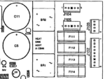
Understanding the Layout
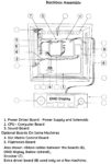
The common circuity is located in the backbox as shown in the picture. Not all boards are in all machines. Early alpha numeric machines did not have a DMD board. And Fliptronics was introduced with The Addams Family. More complex machines added boards under the playfield, usually for optical switches (optos) and some motors. The power transformer and a power filter box are located below, in the cabinet.
WPC89 Fliptronics is shown in the first picture. But all WPC89 machines have a similar layout. Alpha Numeric machines lack DMD and Fliptronics boards, early DMD machines lack Fliptronics boards, and WPC-S is essentially the same as WPC89, with the only change in the components on the CPU board.
WPC95 has a completely changed layout. And the plug numbers on the boards are also different.
Voltages Required
There must be +5, +12 and ground present on the CPU board or it will not work. Other boards such as display, sound and Fliptronics require other voltages.
There is always the hazard that the voltages will be too high and a board can be damaged. With Williams WPC, while that possibility is quite remote, it may be wise to disconnect the power to the other boards and concentrate on the power supply by itself.
We usually take a fine Sharpie and mark the plugs on their side with the plug number. But these plugs are keyed (check the plugs for the key!) and they are difficult to mess up.
Many of these connectors pins on these boards are not used.
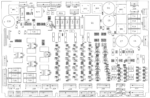
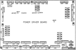
Power Driver Board
The Power Driver Board is the largest board in the backbox. It serves two functions: 1) convert the AC from the transformer to DC used by the other board, and 2) control (or ‘Drive’) the solenoids, flashers and light bulbs.
What can go wrong
1) Connectors (header pins and plugs), wires. Burned, broken wires, tarnished header pins. Check to see if any look burned or discolored. If they do, replace both the pins and the plugs.
2) Board problems – voltage regulator, capacitors, rectifiers, etc. We will test for those.
3) The +5 is the most problematic on WPC89 and WPC-S. Issues with the regulator, bridge and large filter capacitor are the most common.
4) Less common are issues with the +12 (digital), but they do occur.
Many of these problems can be easily fixed. The voltage regulator is easily replaced. Replacing the large electrolytic capacitors and the bridge rectifiers requires advanced desoldering / soldering skills. Many of these boards have been damaged during attempted replacements, so this should not be attempted by beginners.
Note that the WPC95 power supply is far more reliable than the WPC89 & WPC-S power supply. But with age, this can fail too, especially as the electrolytic caps get old.
We do not recommend replacing any of these parts unless there is a problem with them. Replacing a working part rarely improves the board’s reliability and can damage the board. Example: Don’t replace a working bridge rectifier or transistor. Electrolytic capacitors, however, are an exception to this rule.
To Isolate the Power Supply (Optional)
For WPC89 and WPC-S:
J101 (+12 digital and +5)
Power Driver Board Voltage Readings
Measure the DC values on the Power Driver Board. Except for the 5V, they don’t have to be exact. When possible, connect the black lead to ground on this board – use the test point (TP). Note that there are LEDs on these boards that confirm if a voltage is on. But these LEDs do not give voltage, so using a DVM is better. Test points (TP) are indicated on the photos below.
WPC89 & WPC-S

TP1 = +12 (unregulated, can vary, 10 – 14 is typical)
TP8 = +18 (Lamps)

TP100 = +12 (should be very close to +12)
TP101 = +5 Digital (should be very close to +5 or 5.1)
Troubleshooting the Voltages
For WPC89 and WPC-S
If the V DC is good feeding into Q1, the LM323 voltage regulator, but the +5 at TP2 is low or absent, then the LM323 is likely defective and should be replaced. Or replaced with the EzSBC modern equivalent. Prior to doing so, check the back of the board and insure that the solder connections for the LM323 are not damaged.
Note that it is very difficult to test the voltage to the input to the LM323 as there is not a TP for it. The easiest way is to turn the power off, then clip a test lead to the top left lead of bridge rectifier BR2. Use the ground TP5 on this board for your black lead. Then turn the power back on.
This voltage is unregulated, but should read about +9 V DC, but higher is not unusual. The LM323 spec is that the input voltage has to be between 7.5 and 15 V DC.
If the voltage is below about 8.5 volts DC, you may have an issue with BR2 or C5. Check the AC voltage on pins 1 & 2 on J101. It s should be about 9 V AC. If significantly lower, then check to insure that the transformer is setup for your wall voltage. Also check to insure that your wall voltage is not low.
If the AC V is good, but the output of BR2 is low, it maybe the capacitor C5 or the bridge rectifier BR2. If BR2 shorts, fuse F113 will blow. If one or more of ‘sides’ of the bridge fail open, then the +12 at TP1 will drop. Test BR2 with the diode tester and J101 removed – power off.
It the AC is good, but the output of BR2 is low, check the large electrolytic ‘cans’ for leakage or deformity. The top should be flat. If not, replace them. C5 is the one used in the 5v power supply. Other large capacitors are used in the other power supplies.
If TP1 is low (+12V), similarly check C30 and BR5. The AC comes in J112, pins (1 or 2) and pins (3 or 5).
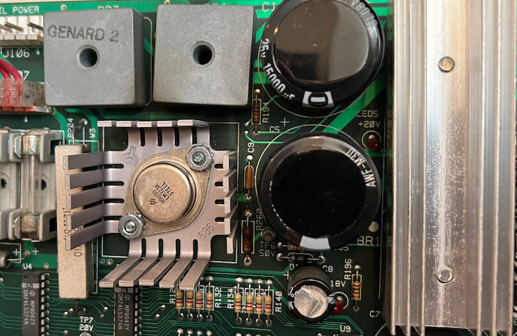
If TP2 (+5 V DC) is high, it could be a defective LM323 voltage regulator. It could also be a bad ground. If pushing on the LM323 causes the 5V DC to jump around, try tightening the nuts holding the voltage regulator to the heat sink. Those nuts and screws are the ground for the regulator. Don’t over tighten as these can be broken off.
If this does not work, remove the board and inspect the back. Insure the screws make good contact with the ground trace.
Less likely are issues with +12 (Digital) at TP3 or +18 at TP8. If TP8 is good, then the voltage regulator LM7812, Q2, has likely failed. If the +18 at TP8 is low, suspect the bridge BR1 or the large caps C7 & C6.
For WPC95
Less likely are issues with +12 (Regulated) at TP100 or +18 at TP102. If TP102 is good, then the voltage regulator LM7812, Q2, has likely failed. If the +18 at TP8 is low, suspect the one of the diodes D11 – D14 or the large caps C11 & C12.
If one decides to replace the LM317K with the more modern EzSBC – something which we have never done and do not recommend – it will be necessary to remove R1 and R2 and short pin 3 to ground. Failure to properly ground the EzSBC will result in failure of the voltage regulation.
If TP103 is low, it should be one of the diodes D3 – D6, C8 or the fuse / fuse holder.
Note that the +5 voltage regulation on WPC95 is better designed than the WPC89 and WPC-S design. The +5 has its own power supply and does not use the +12. It also uses a LM317K at Q1. The LM317K is an adjustable voltage regulator. Williams set the +5 V DC to be a little high at about 5.1 via the resistor network of R1 and R2. This makes means the CPU is far less likely to have reset issues.
If TP101 is low, check the output of the diodes D7 – D10 (the banded side of D9 or D10), or the + side of C9 – there is not a test point here and this may be hard to check. If this voltage is significantly below +12 V, then diode check D7 – D10. If those are good, inspect C9 – look for damage, leaking or bulging. If present replace C9.
If there is +12 at the + side of C9, check R1 and R2. Also check the solder connections on the back of Q1 / LM317K. If all of those are good, the LM317K might have failed.
Other Board Voltages
If you have plugged back in the Power Driver Board and the game still does not boot, there could be other boards involved:
DMD Driver Board – For DMD machines – if your display is not working.
Fliptronics Board – WPC pinball machines from The Addams Family on (~1992) have this board.
Sound Board – If your sound is not working, start here.
CPU Board – The CPU does not create its own power, but it has to get there for it to boot.
CPU Board
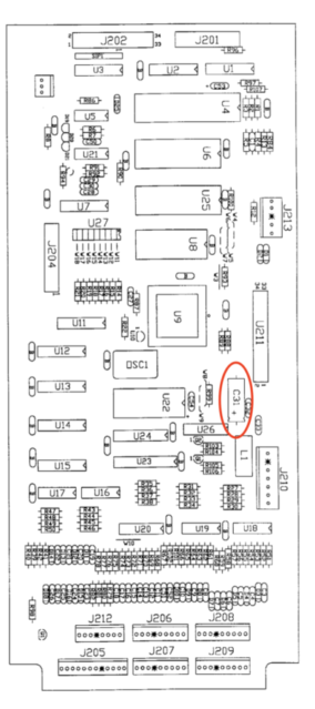
The power comes in J210 in all models. Unfortunately, there are not convenient test points to confirm the voltages.
It is always best to use the ground on the board under test. On the CPU, this takes a little creativity. On J210, pins 1 & 3 are ground. If you have a clip lead with a hook, unplug J210 and put the hook around pin 1, towards the outside, then push J210 all the way back on. Otherwise, the screws holding the board in place should be grounded.
Alternatively, the (-) minus side of C31 is ground and the (+) plus side of C31 is 5 V DC.
What can go wrong
Not much, and a whole lot. This is generally a reliable board as long as you don’t let the batteries leak. Or put solenoid voltage into the switch matrix. And a few other things.
But the board cannot boot if the voltages and ground are not present.
J210 Voltage Tests
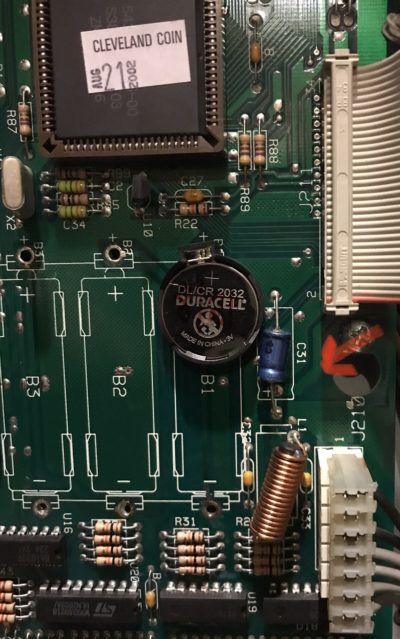
Pins
1,3 – ground. The (-) side of C31 can also be used.
4, 5 – +5 (4.9 – 5.2). The + side of C31 can also be used.
6, 7 – +12
Troubleshooting
If the voltages are good on J210, including ground (this is important), then the CPU could be defective. However, it is possible that one of the other connected boards could prevent booting.
Turn the power off and disconnect the ribbon cables coming off the top of this CPU board at J201 and J202 if present. Also unplug the ribbon cable at J204 if present. Turn on the power and see if the game boots. With these ribbon cables removed, there will not be sound nor will the displays work. LED 203 should be flashing if the CPU has booted. If the game now boots one of the other boards is preventing the game from starting. Sometimes this is because the ribbon cable is not plugged in properly on another board. Carefully inspect the ribbon cables and insure it is inserted on both sets of pins.
Other issues that could prevent booting might be socketed chips not being seated properly including the large almost square ASIC chip.
DMD Driver Board (WPC 89 and WPC-S)
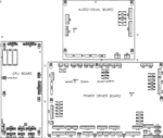
Audio Visual Board (WPC95)
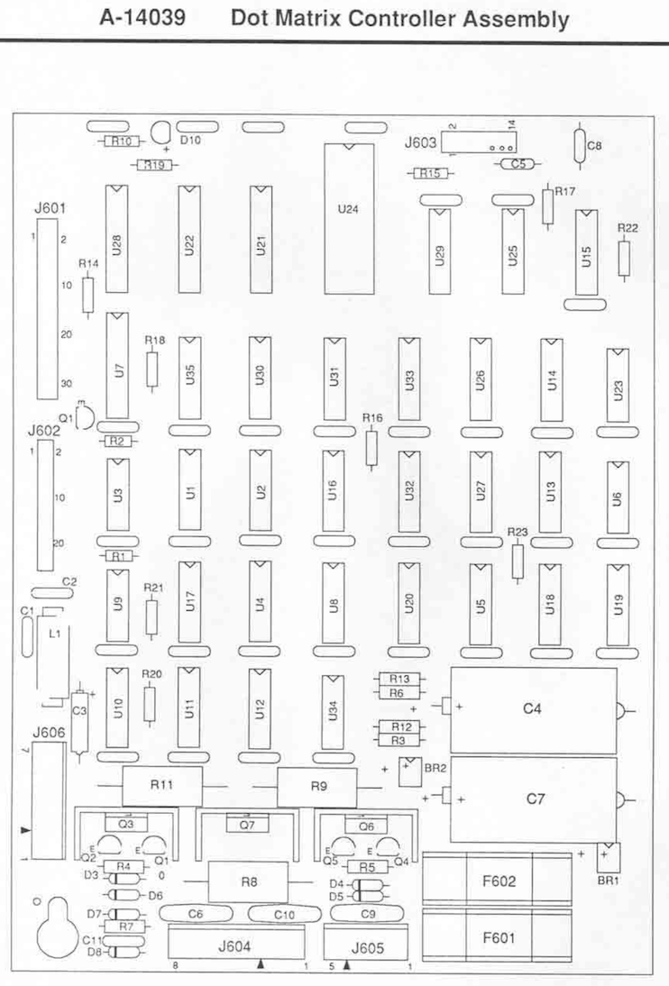
Note, this board has extremely high and dangerous voltages. Prior to proceeding, read all of the cautions.
This board requires +5 and +12 V DC from the Power Driver Board via J606. But it also receives AC directly from the transformer and converts it to high voltages at J605.
Note that WPC95 combined the DMD board with the audio board. WPC89 and WPC-S has a separate board. The following applies only to the ‘Visual’ part of the WPC95 board.
There are two sections to this board: high voltage supply, and, the digital driver section. We are only going to check the high voltage section.
What can go wrong
1) The high voltage section of the Williams WPC board is prone to overheating and component failures.
2) Board problems – voltage regulator, capacitors, rectifiers, etc. Check to see if any look burned or discolored. If they do, replace both the pins and the plugs.
Voltage Tests

The easiest place to test these voltages are not on this board, but on the DMD display itself. The display has pins that are bent at a 90 degree angle from the board. That makes access to those pins rather easy.
Note: It is important to not accidentally short one pin to the other when taking these readings.
All DMDs use this same plug. The #1 pin is on the left. It would be better to use a ground on this board, but if not easily attached to, use the Power Driver Board ground, or another available ground.
Pin Measurements (all V DC):
#1 = – 120
#2 = -108
#3 = key, N/A
#4&5 = Ground (read nearly zero vs. Power Driver Board, but may get a very low reading)
#6 = +5 (4.9 – 5.2)
#7 = +12
#8 = +60
Troubleshooting
The +5 and +12 volts come from the power driver board. If they are absent here, but present at the Power Driver Board, it is likely a connector. There are a few components for +12 that could go bad, but this is unlikely.
#1 and #2 can vary a little bit from these readings, but there must be a 12 volt difference between them.
If pins #1, #2 or #8 are wrong, either rebuild the power supply or replace the board. The power supply in this board tends to get hot and that damages the board. Since replacement boards are available, it is better to not fix this board anymore.
Fliptronics Board (WPC89 & WPC-S only)
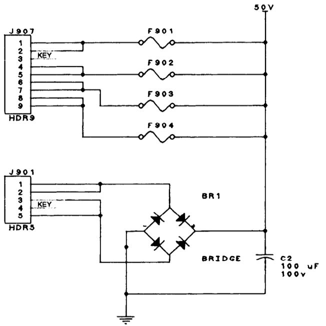
WPC pinball machines use the Fliptronics technology from The Addams Family, on. The Addams Family was the only one where two boards were used, the second board to create the 50 V DC for the flippers. All other machines used Fliptronics 2 that had the 50 V power supply built in. Fliptronics 2 also has the coil diodes built into this board, a major advantage.
If all of your flippers are not working, it could be this power supply. Note that for The Addams Family, the +50 volts is done on the the power supply board for Fliptronics 1.
This board also receives +12, +5 and ground from the Power Driver Board, via J904 and cannot operate without those voltages and ground.
What can go wrong
The AC comes into the Power Driver Board and then back out to the Fliptronics Board. This Fliptronics board consists of a bridge rectifier to convert the AC to +50 V DC, and fuses for each flipper. If the bridge rectifier goes bad (shorts), F112 on the Power Driver Board will blow.
If one of the other fuses blows on this board, either the flipper coil is damaged or one of the TIP 102 or TIP36C transistors is shorted.
Voltage Tests
Set your DVM to V DC. Connect the black lead to any ground. Touch the red lead to each side, one at a time to fuse clips F901 – F904. Both sides of each fuse will likely read higher than the 50 V, because there is not a load. 70 V DC is common.
There are not any test points on this board to confirm +5, +12 and ground. But C1 is a good place to check +5 and ground. Connect your black lead to ground on the Power Driver Board TP5.
C1 (+) side = +5 V DC (same as +5 on the Power Driver Board).
C1 (-) side = ground (read nearly zero vs. Power Driver Board, but may get a very low reading).
Troubleshooting
+50 V DC
Note that there is not a fuse on the Fliptronics 2 board before the bridge rectifier. That means if this bridge is bad, then fuse F112 on the Power Driver Board will blow. The problem with this setup is that if F112 blows, it could be a shorted bridge BR3 on the Power Driver Board, or bridge BR1 on the Fliptronics 2 board. The way to troubleshoot this is to unplug J901 and replace F112. If F112 blows, it is BR3 on the Power Driver. If F112 does not blow, it is BR1 on the Fliptronics 2 board.
If +50 V voltage is absent on any fuse on the Fliptronics 2 board, then check fuse F112. If that is good, and the other solenoids have power, either you have a connection problem, or the bridge is open (unlikely).
If voltage is present on one side of a fuse, but not the other, the fuse is blown. Replace it and hope it does not blow again.
If the fuse blows again, did a flipper activate before the fuse blew? If yes, you have a shorted TIP 102 or TIP36C. If no, then the flipper coil is likely bad (shorted). Or, the diode on the flipper coil is shorted. Or (unlikely) the diode for that coil (D17 through D24) on the Fliptronics 2 board is shorted.
If all the voltages check out, but a flipper or all of them do not work, you have a problem with the control side of this board. That could be:
* The 50 V is not getting to the flipper coils. Check the voltage at the coils.
* Ribbon cable to the Fliptronics board / CPU. Either side.
* U2 (74HCT374) on the Fliptronics board is bad.
* Flipper switches or flipper opto switches are bad or not connected properly.
+12, +5 and ground
If these are missing and they are good on the Power Driver Board, then you have a connector (plug, wire, header pin) problem.
Fliptronics Board (WPC95)

WPC95 uses the same technology as used in the Fliptronics 2 board, except that it is built into the Power Driver Board.
What can go wrong
Not much with the power. The flipper power goes to the coils from J119 and this power is generated from the same power that runs the other high power 50 V DC solenoids. If you tested TP 105 on the Power Driver Board and it is good, then the power to the flippers should be good.
Voltage Tests
Set your DVM to V DC. Test TP 105. If 50 V is present, then the coils should have power.
Connect the black lead to any ground. Touch the red lead to each side, one at a time to fuse clips F115 – F118. Both sides of each fuse will likely read higher than the 50 V, because there is not a load. 70 V DC is common.
Troubleshooting
If no voltage is present on any fuse, then check fuse F107 & 108. Those will blow if one of the diodes in the power supply is shorted.
If voltage is present on one side of a fuses F115 – F118, but not the other, the fuse is blown. Replace it and hope it does not blow again.
If the fuse blows again, did a flipper activate before the fuse blew? If yes, you have a shorted TIP 102 or TIP36C or a diode on the coil is shorted (unlikely). If no, then the flipper coil is likely bad (open).
If all the voltages check out, but a flipper or all of them do not work, you have a problem with the control side of this board. That could be:
* Ribbon cable to the Power Driver board / CPU, J211 to J102. Either side. But that would affect a lot of solenoids.
* U5 (74HCT244) is bad.
* Flipper switches or flipper opto switches are bad or not connected properly.
* Power is not getting to the flipper coils.
Audio Board – Sound board


WPC89 and WPC-S have a separate audio board. WPC95 combines the audio board with the video. This applies to the audio board only.
WPC89 had two generations of sound boards: original and DCS.
What can go wrong
The WPC 89 sound board uses the + 5 V DC from the Power Driver Board. But they also generate +12 V DC and -12 V DC from AC supplied to the board. It is this power supply that can be the cause of failure. The 1 uF Tantalum capacitors have a bad habit of failing, sometimes by vaporizing. Inspect the board for signs of a failed small capacitor.
WPC89 DCS and WPC95 sound boards (Audio Video Boards) generate their own +5 and -5 V DC.
Voltage Tests
Set your DVM to V DC. If possible, connect your black ground probe to a ground on the board (see the above schematics.
WPC89 (pre-DCS) Ground are pins 6 & 7 on J501 and pin 2 of J503. The (+) side of C24 is also ground, but getting to that is tough. The corner screws and the pad around them are also ground.
There are not any test points, but the easiest way to check the voltages are at the pins of J503.
J503 Pins (V DC)
1 = +5 from the Power Driver Board
2 = Ground
3 = -12 V
4 = +12 V
Troubleshooting
If the +12 or -12 are missing, then it is usually the failure of the voltage regulators LM7812 (+12) or LM7912 (-12) or one of the small Tantalum caps. Less likely is a failure of one of the discrete power supply diodes. C24 or C25 can fail or leak. Inspect those caps for leaks or bulges. Also check fuses F501 & F502. Failure of the fuses can mean a shorted diode or shorted / failed capacitor.
WPC89 DCS

WPC89 DCS has a similar power supply except that it generates +5 and -5 VDC.
Ground are pins 6 & 7 on J4 and pins 4 & 5 of J3. The corner screws and the pad around them are also ground.
There are not any test points and it is difficult to test the +5 and -5 DC. U25 pin 1 has +5. U26 pin 3 has -5. It might be easier to connect to the (+) end of Tantalum cap C18 which has +5. C19 on the (-) end is -5.
Troubleshooting
If the +5 or -5 are missing, then it is usually the failure of the voltage regulators LM7805 (+5) or LM7905 (-5) or one of the small Tantalum caps. Less likely is a failure of one of the discrete power supply diodes. C20 or C21 can fail or leak. Inspect those caps for leaks or bulges. Also check fuses F501 & F502. Failure of the fuses can mean a shorted diode or shorted / failed capacitor.
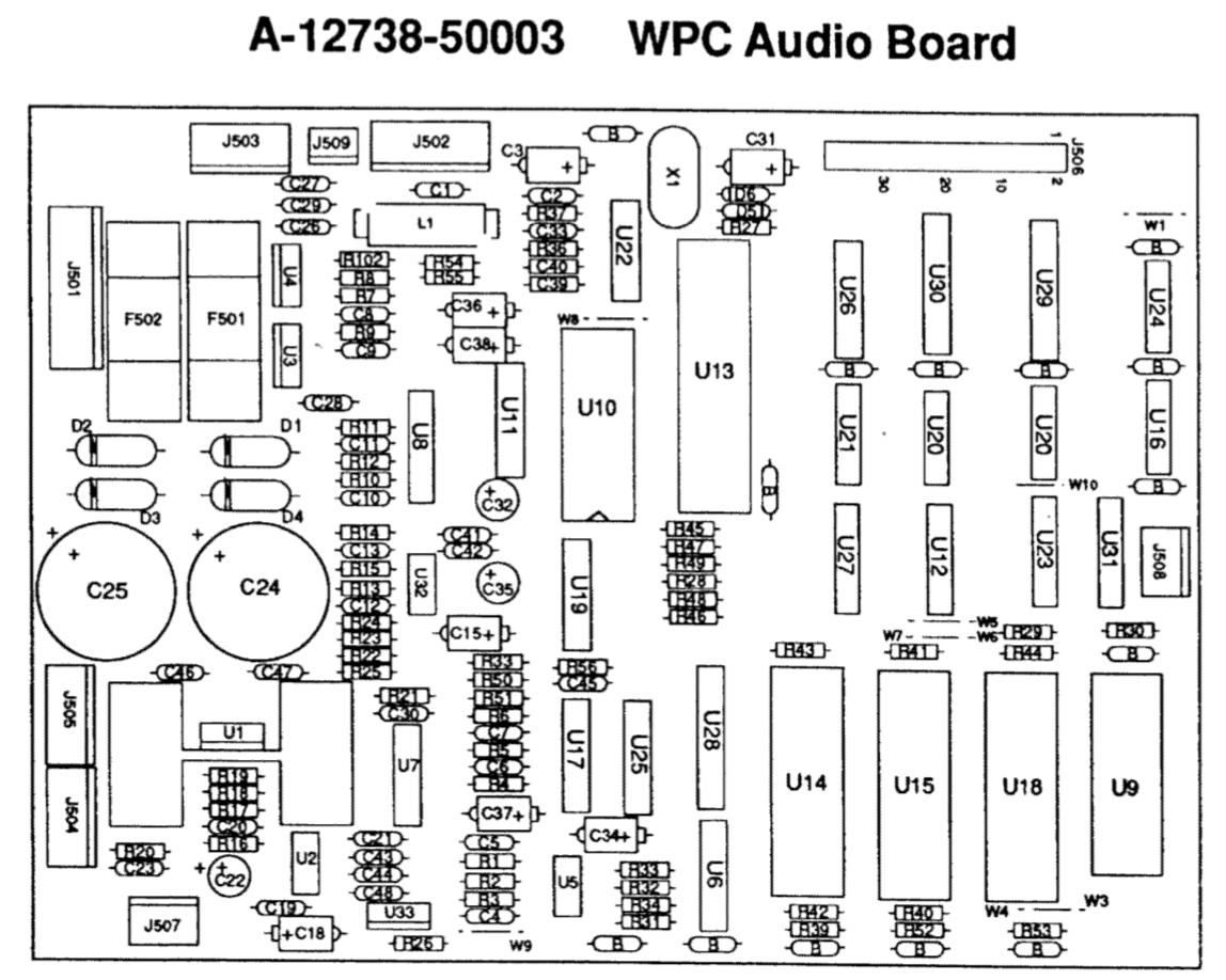
WPC95 Audio Visual Board (Audio only)
WPC95 has a similar power supply that generates +5 and -5 VDC.
Ground are pins 5 & 6 on J605 and pins 3 & 4 of J505 and J504. The corner screws and the pad around them are also ground.
There are not any test points and it is difficult to test the +5 and -5 DC. U7 pin 1 has +5. U8 pin 3 has -5. It is also possible to check for these voltages on several of the ICs. U5 and U6 have +5 on pin 5, and -5 on pin 3.
Troubleshooting
If the +5 or -5 are missing, then it is usually the failure of the voltage regulators LM7805 (+5) or LM7905. Less likely is a failure of one of the discrete power supply diodes. C36 or C37 can fail or leak. Inspect those caps for leaks or bulges. Also check fuses F501 & F502. Failure of the fuses can mean a shorted diode or shorted / failed capacitor.
External Links
Williams WPC PowerDriver Board Wholesale Capacitor Replacement
Fixing WPC Game Resets – By far the best and most up to date step-by-step troubleshooting procedure.
100uF/10V Phillips Capacitors – These capacitors go bad, drag down the +5 V in WPC89 and WPC-S pins.
Understanding ESR – For those non-electrical engineers, understanding what ESR is (previous link).
Comments
Comments, including suggestions, improvements, errors, etc. are welcome (see below).
If you have a specific question about your game that does not directly apply to this page, please see our FAQ section.