How to fix a malfunctioning switch matrix on a Williams / Bally WPC pinball machine
The cause of a malfunctioning switch matrix is either a playfield wiring problem, missing diode on a switch, or a circuit board problem.
Note: For most images, click on the thumbnail for a full sized image.
Understanding the Switch Matrix

The columns are constantly sending out pulses (strobing). But the rows only get a signal when a switch is closed. On the picture to the right, a single switch in row one is closed. The computer knows which column from the timing of the pulse. The computer knows which row from where the signal arrives. If the pulse is from column 3 going to row 1, the switch would be 31 (assuming switches are labeled by column and row).
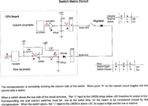
The image to the right is from a Williams WPC manual explaining the way the switch matrix works. It is nice to understand this, but necessary for troubleshooting.
If you are running into issues where two (or more) switches register when one is closed, or two or more lamps light when only one should; the best guide for troubleshooting false switch or lamps issues we have ever read is here.
Williams / Bally WPC Switch Matrix Testing
Determining Where the problem is located
Prior to proceeding, read about Switch Matrix Troubleshooting.
Is it on the Playfield.
Part of a Column Not Working
If only part of a row or column is not working, then the issue is on the playfield. It is not on the CPU circuit board.
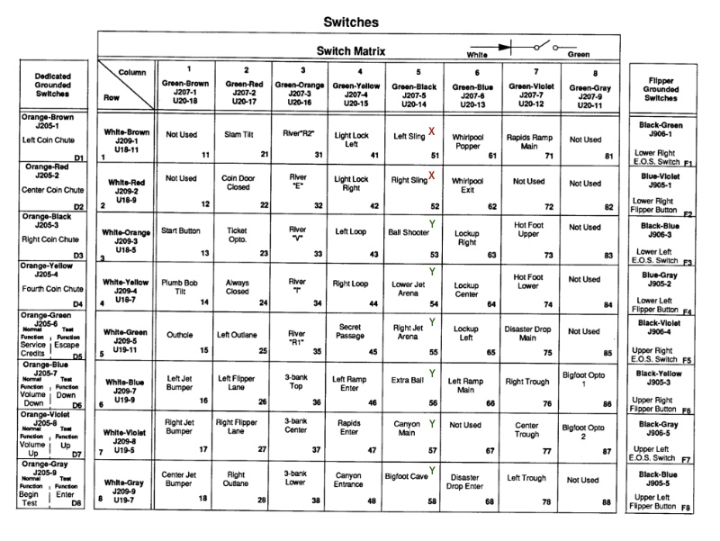
This will take some work to find. Pull out the switch matrix (best to make a copy of it) and mark which switches are working and which are not. In the photo, the user has marked what switches in the column are working and what are not.
In this example, left sling and right sling are not working. Lift up the playfield and look for those two switches. That column as Green-Black wires going from switch to switch. That wire is likely to be broken at the switch. If the wires look good at those two switches, look at the others in that column. The break is likely to be there.
Sometimes it is not a complete break, but a frayed wire. Look carefully. 99% of the time the issue is at the connection to the switch. But if you are really unlucky, the break could be between the switches but that is darned unlikely.
If a broken connection isn’t found, try running a clip lead from the (Green-Black in this case) wire on a working switch to a non-working switch. If the non-working switches now work, you have found the area of the problem. Just keep searching to find the break.
Be very careful not to short any wire or clip lead from that switch matrix to solenoid lamp voltage or you will blow an IC on the CPU board.
A Single Switch Not Working
This is unlikely to be the switch matrix, but it could be a break in the wire going to the last switch in the switch matrix. It is more likely to be a defective switch.
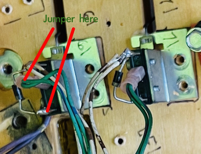
Either test the switch with a volt meter set to resistance, or jump the switch. Note, jump the two tabs on the switch that do not have both a wire and diode connected. Usually, this is a white wire (with a color stripe) to a green wire (with a color stripe).
Note that one of the two wires has a connector on it. It will be necessary to access the tab on the switch below that connector. Other side to the end of the diode that does not have a wire connected.
If jumping those two wires activates the switch, then the switch is defective.
An Entire Column or Row is Out
This could be a wire break on the playfield (unlikely), a connection problem at the CPU or a defective CPU board.
First, test the switch matrix in the CPU.
Enter the service menu to the switch matrix test. See the manual for this procedure. Then unplug the column and row plugs. Be certain to unplug all of the switch matrix plugs including the cabinet switches (dedicated / direct switches can remain plugged in). In a WPC89 pin, that would be all of the plugs on the bottom of the CPU (see photo below) except plug J205.

Next, connect a small clip lead that would involve a switch that is not working. It must include the column or row that is involved. For example, of the entire row 5 is out, connect a clip lead from any column (J206 or J207) to pin 5 of J208 or J209. Since the switch matrix is not connected, no diode is needed.
To test a column, pick that column and connect it to any row. For example, if column 8 is not working, connect a clip lead from pin 9 of J206 or J207 to any pin on J208 or J209. If that switch in the non-working row or column registers, the board is working. Troubleshoot your plugs and wiring on the playfield or cabinet. If that does not register, the problem is on this CPU board.
Note that plugs J206 and J207 are identical and either can be used. Also plugs J208 and J209 are identical. Plug J212 is for cabinet switches and pins 1, 2, 3 are columns while 4, 6, 7 & 8 are rows. WPC89 and WPC-S are identical. WPC95 is similar except J208 pins 10 – 14 are not part of the switch matrix. If the issue is a switch matrix row, jump to Williams / Bally WPC Row Testing Procedure, below.
Testing the WPC Switch Matrix With A Digital Probe
Testing Columns
Testing the columns with a digital probe is relatively simple. Each column should be pulsing all of the time. If it is not, find the problem by tracing where the pulses disappear. First, hook up your digital probe (See “Using the Probe“) to +12V DC and ground. Check to see that it is operating by touching the pins on J206 or J207. All pins (except the broken one) should cause a pulse on the probe. If not, check the connections and settings.
Select the column that is not working (see the circuit diagram). For example, if it is column 1, that would be J206 or J207 pin 1 (A). If you get a pulse, it is working and your problem is not on the board. If it is not pulsing, check the other pins to insure they are pulsing. If they are, then the problem is on this board.
For column 1, if not pulsing at J206 or J207 pin 1, go to U20 pin
18 (B) of ULN-2803. If you get the pulse there, then the problem is a break in the trace on the circuit board between this IC and the plug. Sadly, many of the problems here are due to battery leakage, so look for that.
If not pulsing at U20 pin 18 (B), go to U20 pin 1 (C). If pulsing, then the problem is with U20*.
If not pulsing, go to U14 pin 9 (D). If pulsing, there is a break in the line between U14 pin 9
and U20 pin 1.
If not pulsing at U14 pin 9 (D), then U14 could be defective**. U14 works by converting the digital signal to the pulses we are looking for. Just for fun, insure that those digital pulses are present at those pins 3, 4, 7, 8, 13, 14, 17. If one or more is missing, all your columns should be messed up, not just one.
* Or the resistor package R67 – R74 open or shorted, or C11
shorted, or the trace is shorted to ground, or U20 is not grounded at pin 9.
** Or pin 8 is not grounded, pin 16 does not have +5, or the data coming in pins 3, 4, 7, 8, 13, 14, 17 is missing.
WPC Column Testing Procedure
1) Test (A). If present, problem is not at the board.
If no pulse at (A), test (B). If at (B) expect break in the trace between A & B.
2) If no pulse at (B), test (C). If pulse at (C) expect U20 to be defective.
3) If no pulse at (C), test (D). If pulse at (D), expect break in the trace between (C) and (D).
4) If no pulse at (D), expect U14 to be defective.
Note: prior to replacing an IC check to insure that the IC is grounded and also gets power. A defective resistor package at R67 – R74 can also kill the pulses on the output of U20.
Williams / Bally WPC Row Testing Procedure
First, hook up your digital probe (See “Using the Probe“) to +12V DC. Check to see that it is operating by touching the pins on J206 or J207. All pins should cause a pulse on the probe. If not, check the connections and settings.
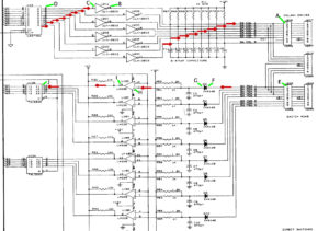
Next, consult the switch matrix circuit diagram. The drawing shows the continued pulsing of the columns. Connect a clip lead from any column connection on J206 to the broken row at J208. For example, if row 7 is to be tested, connect to J208 pin #8. In the example, row 1 is under test.
Next, touch your diode to the pin where the clip lead is connected (E). It must pulse or your connection or probe is not working. Then move to diode (F). If no pulse, then the trace is bad – frequently caused by battery leakage.
If there is a pulse, move to the other side of the diode. If no pulse, the diode is bad. Or, the bridge network (R52 – R66) is defective.

If there is a pulse, move to the LM339, U18 or U19. In this case, check leg 11(H). If no pulse, the trace from the diode is bad (again, check corrosion), or less likely the resistor has failed. Go back and check the trace and either side of the resistor to find the break.
If pulsing at leg 11, check the output. In this case it is leg 13 (I). If no pulse, then the LM 339 is defective. Or, less likely, the 10k resistor R30 is bad.
If pulsing at leg 13 (I), move onto the 74LS240, U13, and check the proper leg (J). If not pulsing, other trace is bad between there and (I) the LM339, U18 or U19.
If it is pulsing at (J), then the 74LS240 might be defective. Also check for the presence of pulses at lets 3, 5, 7, 9 (or 12, 14, 16, 18). It is possible for one part of the 74LS240, U13, to be bad. we would replace it and hope it fixes the problem.