Switch Matrix – Theory and Troubleshooting
Reproduced with permission from terryb.
Written by terryb
All solid state pinball’s use a switch matrix and although the actual implementation may vary slightly, the theory and troubleshooting are the same.
The purpose of the switch matrix is to reduce the number of driver circuits from 64 to 16 and minimize playfield wiring. This is achieved by pulsing each column sequentially while monitoring all of the rows. This is why the column is called the strobe, or send side, and the row is called the return side.
For a list of common problems and troubleshooting, you can jump to this section of the document.
Switch Matrix Theory
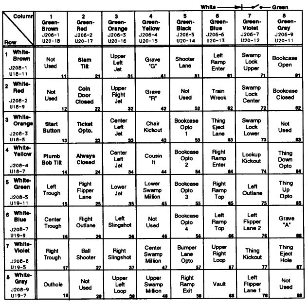
Image 1 is the switch matrix from an Addams Family. The wire color, board connector and pin, and the IC or transistor identifier are provided for each row and column. So for any switch we can move left across the row to get the return side info and up the column to get the send (or strobe) side info. The switch number, which is displayed during diagnostic tests and on the Switch Locations page in the manual, is also provided.
Most of this information is also available in the system diagnostics.
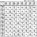

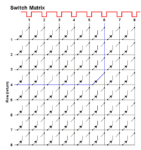
Note: Switch columns and rows are not wired in the same order as they are shown on the switch matrix. For example in column 6 the physical wire might go from “Left Ramp Enter” to “Thing Eject Lane” to “Train Wreck.”
Each column of switches is connected by a green wire with a colored stripe (for example, green-red for column 2) running from one switch to the next. The same is true of each row, except in this case it’s a white wire with a colored stripe. [Editor’s note: Color wires are for WPC games. Other manufacturers wire colors may vary.]
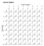
Each switch has an associated blocking diode as shown in Image 2. Since current can flow in only one direction through the diode, the result is isolation of the switch when it’s closed. If this isolation is lost the switch matrix will exhibit bizarre behavior. The root cause will be a reversed diode, shorted diode, switch improperly wired or diode lead touching one of the other switch lugs (this is common on switches where the pinball can hit them).
Editor’s note: If performing a diode test on a microswitch (enclosed unit), the switch must be held closed. If the diode test is performed on an ‘open’ switch, the diode will read shorted.
In some early solid state games there is also a capacitor across the switch. The purpose of the capacitor is to “stretch” the closure of the switch (extend the pulse width) so the CPU can reliably determine the switch has been closed.
Note: On WPC games switch 24 is always closed (there actually is no switch) and the blocking diode is located on the coin door board.
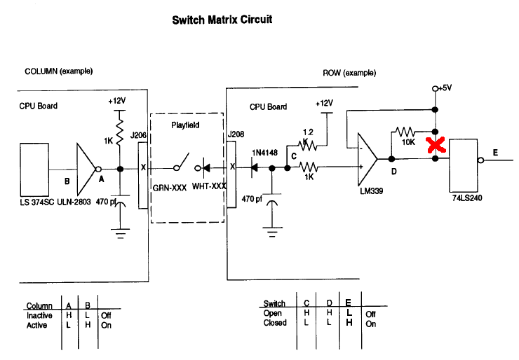
The inactive state of each column is high (test point A in image 5), thanks to the 12 volt pull-up resistor on the output of the ULN2803. The inactive state of the row is also high (test point C in image 5), because of the 12 volt pull-up resistor on the input of the LM339.
Note: There is an error in the WPC manual in regards to the switch matrix circuit in Image 5 (it shows a connection that does not exist), which has been noted in the image.
If you check at the switch while in the inactive state, both the column side of the switch and the row side (the side without a band) of the diode will be high.
When the system strobes the columns, the output of the ULN2803 on the CPU goes low (test point A in image 5) and the column side of all the switches in that column go low. If a switch is closed, then the row side of the diode will be pulled down close to ground. When the row goes low (test point C in image 5) the LM339 on the CPU senses a switch is closed.
If you check at the switch in active mode, the column side of the switch will be low and the row side of the diode will be low if the switch is closed or high if the switch is open.
The matrix strobes each column in sequence, pulling down column 1 and checking all of the rows, then strobes column 2 while checking all of the rows, and so on. This sensing happens at a rate of 500 reads per second.

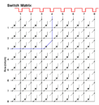
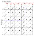
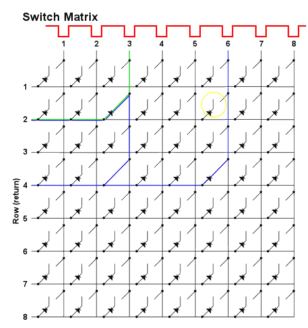
Image 3 shows a pulsed signal alternating across the 8 columns. The columns are strobed at 500 pulses per second, so there is 2ms between each column being pulsed. So at 2ms column 1 is pulsed low, at 4ms column 2 is pulsed low, etc.
In Image 3, switch 43 is closed (column 4, row 3). The system will read a low on row 3 when column 4 is pulsed (the blue line shows the current path) and determine the switch in column 4 and row 3 is closed.

By cycling through each column sequentially, the system can differentiate between the switches in each column while the rows are separated by the blocking diodes. If a diode is shorted, or has been installed incorrectly, the system will get confused since the isolation between switches no longer exists.
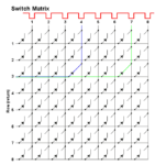
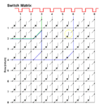
In Image 4 switch 43 is pulsed low at 8ms and switch 73 goes low at 14ms so even though they are in the same row, the system knows two different switches have been closed.
Note: All matrix circuits are pulsed and are best tested with a logic probe or oscilloscope.
All testing should be done using the switch edge diagnostics and all balls removed from the game. It’s easy to miss relationships between different switches when in game mode.
Opto Boards
Keep in mind when troubleshooting switch matrix problems that optos work differently than mechanical switches. Since there is no physical connection between the strobe and the return side of the opto, it cannot directly cause a problem like a shorted blocking diode can. Instead the opto board can cause problems like ground short errors or symptoms that resemble a shorted diode.
As I will explain later, knowing which switches are closed is an important part of troubleshooting random switch indications. In the case of optos though it doesn’t matter if the switch is open or closed since there is no physical connection as described above.
If there are optos in the row or column you are having problems with, remove the connectors from the board and see if your problem goes away.
Troubleshooting the Switch Matrix
There are a few common problems you will come across with the switch matrix.
- I recently worked on the game or it’s new to me and has matrix problems.
- All of the switches in a column are not working.
- All of the switches in a row are not working.
- Two or more consecutive, but not all switches, in a column or row are not working.
- Row or column of switches all show closed.
- Ground short error in switch edge test.
- Closing any switch in a row, or column, causes a switch in another row, or column, to indicate closed.
- Random switch indications.
Human Error
Before troubleshooting any problem, the first question to ask yourself is if you have recently done any work on the game. Or if the game is new to you and has problems, never rule out mis-wiring by the previous owner.
If after replacing a diode/switch you have switches indicating closed when they shouldn’t be the diode or the wiring is reversed. Check your setup and make sure the band on the diode is oriented towards the switch and then the green wire (see Image 9).
An entire column is locked on or not working. The column driver is extremely vulnerable to a short from GI lighting, the lamp matrix and flasher/solenoid power. Flasher and solenoid voltages can take a while to go to zero, so damage can occur even after powering off the game.
If one of these voltages does contact a switch, then as soon as the column driver (ULN2803) scans it, it overloads and fuses. Flasher/solenoid voltages and above can blow through the ULN2803 and take out the 74LS374 that drives it, potentially crippling the CPU.
And as always check all connectors and then check them again.
Column Failure
First we’ll cover a column of switches not working, and the first question we need to answer is whether the problem is on the playfield or the circuit board. There are a couple of ways you can check this out. The following method works fine or you can use the jumper method explained at the end of this document or the Siegcraft switch matrix tester.
The quickest approach is to test continuity between the column wire under the playfield (with the game off) and where the column connector is soldered to the circuit board (on the back side of the circuit board). It is important to test to the board, not just to the connector, since you could have a bad connector.
If we use Addams Family as an example, and column 3 is out, we can see from the manual (see Image 1) it’s a green-orange wire and the connector is J207/J206 pin 3.
While you’re at it, also test from the strobe wire to ground just to make sure there’s not a short.
If both tests read good, you’ve got a board problem. If you want to confirm this you can use the jumper method at the end of this article.
If there is no continuity from the playfield to the board, check the connector and the last section of wire that runs from the playfield to the connector. If you read a short to ground start tracing the wire from beginning to end looking for a short to ground.
If your problem is on the CPU board, it’s a fairly simple circuit, although different manufacturers use slightly different designs. Some will use a transistor as a driver and others will use an inverter or buffer. In the case of Addams Family an inverter is used (see Image 5).
Get your logic probe out and starting at the connector work back through each test point to find where the pulse is getting lost.
Note: The column test point readings in the manual are for use with an oscilloscope or logic probe, not a DMM.
Note: J206 and J207 (column drives) are electrically the same and the connector may go to either one. The same is true of the two switch row connectors, J208 and J209.
Row Failure
The first part of troubleshooting the return circuit is the same as above; use your ohmmeter to test to the circuit board and ground or use the jumper method at the end of this article or the Siegcraft switch matrix tester. If the problem is on the playfield, troubleshoot as above.
If the problem is on the CPU board see Image 5. Get your logic probe out and starting at the connector work back through each test point to find where the pulse is getting lost. The row you are testing needs to be jumpered to a column as described at the end of the article.
Note: The column test point readings in the manual are for use with an oscilloscope or logic probe, not a DMM.
Partial Row or Column Failure
The only way you can get a partial row or column failure is a wiring problem under the playfield. The switches before the problem will work and the switches after the problem will not work since they’re daisy-chained. Use switch diagnostics while following the wire downstream and closing each switch (remember the manual will give you the wire color) until you find the point where the switches quit working.
Somewhere between the non-working switch and the last working switch the wire is broken or there’s a bad connection. The usual problem is a wire has become broken at the solder joint on the switch, which can often look like it’s still connected so you should gently tug any suspect wires.
Row or Column, All Switches Show Closed
This problem is different than random switch indications in that triggering one switch will cause an entire row or column of switches to indicate closed. This can be rather exciting when you hit one target and eight different things all happen at once. You can verify the problem by going into switch diagnostics and manually closing the switch that causes the problem.
Note: Normally closed switches, or some types of board failures, can cause this problem to occur as soon as you start a game.
If the problem is with a column check the associated column wire for a short to ground. Most earlier solid state games have a column driver transistor which is a common cause of this problem (the transistor number will be noted for each column on the switch matrix rather than an IC number). On some games this will be reported as a ground short error.
These problems are typically caused by a row or column circuit staying low or high rather than being pulsed. For a column problem, get out your logic probe and starting at the connector work back through each test point to find where the pulse is getting lost (see Image 5). Do the same with the row circuitry for a row problem.
Note: The column and row test point readings in the manual are for use with an oscilloscope or logic probe, not a DMM.
Ground Short Error
The system will report the row number and wire color for the suspected ground short when in switch test mode (i.e. – Row – X, Wht – XXX). Check the wire looking for something that is pinching it against a metal part or a diode/switch assembly that is bent and touching ground.
If you remove the row and column connectors and the error goes away the problem is most likely on the playfield. If the error continues the problem is with the board. [Editor’s note: On Williams WPC pins, there are four plugs: two to the playfield (a column drive and a switch row), then two to the cabinet. One of the cabinet plugs is to Direct Switches. All four have to be removed to see if this is a playfield / cabinet problem, or a CPU board problem.]
To test the playfield, disconnect the column or row connector and check from the colored wire identified in the error to ground and see if there is a short. [Editor’s note: The two plugs to the cabinet switches need to be removed also. Those are plugs J212 (switch matrix to the cabinet) and J205 (direct switches).] If you do not read a short there is a problem with the switch matrix circuitry, most likely caused by shorting a high voltage to the switch circuitry. See the associated row circuitry (LM339 and 74LS240, Image 5).
Column or Row Short
A column short is indicated by the following symptoms. When any switch in a column is closed, another switch in the same row, but different column, will also indicate closed. For example, on Addams Family the slam tilt (column 2, row 1) falsely indicates closed when the upper left jet switch (column 3, row 1) is closed.
This will also happen in reverse and for every switch in that column. For example, the upper left jet switch (column 3, row 1) will falsely indicate closed when the slam tilt (column 2, row 1) is closed.
This indicates a short between the column 3 wire (green-orange) and column 2 wire (green-red). See Image 1. The best way to find the problem is with a visual inspection.
A row short is indicated by the following symptoms. When any switch in a row is closed, another switch in the same column, but different row , will also indicate closed. This will also happen in reverse and indicates a short between the two row wires.
Random Switch Indications

Random switch indications occur when one switch is closed and another switch erroneously thinks it has also been closed. For example, A ball hits the left sling and one of the pop bumpers fires. This is typically caused by a reversed diode, a shorted diode, the switch improperly wired or diode lead touching one of the other switch lugs. Any of these issues allows current to flow backwards and take a row low that shouldn’t be low at that time.
While this is often a one to one relationship (one switch closes and one switch thinks it’s closed when it isn’t) there can be multiple one to one relationships.

Note: I’ve added a video at the bottom which briefly covers the switch matrix theory of operation and provides detailed information on troubleshooting shorted switch diodes.
In Image 6 you can see a shorted diode at column 3 row 4. Note the switch at column 6 row 4 is closed and nothing bad is happening. Everything will work as expected because although the diode is shorted its associated switch is open.
In Image 7, the switch at column 6 row 4 is closed and the switch with the shorted diode is now closed. Again, nothing bad will happen because all of the other switches in that column are open. But when one of the other column switches is closed…
In Image 8, the switch at column 3 row 2 is closed in addition to the previous switches. Now bad things start to happen. The shorted diode and the closed switch allow row 2 to be taken low when column 6 is pulsed low. So the system falsely thinks the switch at column 6 row 2 is closed (see yellow circle).
In summary, the following must all happen for the problem to show up: the switch with the shorted diode must be closed, another switch in the same row must be closed and another switch in the same column must be closed.
The combination of three closed switches is not as unlikely as you think when you consider multiball, NC switches and commonly closed switches (ball locks or ball trough).
If you map out the three switches on the switch matrix you will have three corners of a rectangle and the fourth corner of the rectangle provides us with a fourth switch. The shorted, or reversed, diode will be on one of these four switches.
Always use the switch edge test when troubleshooting random switch indications. It addition to providing a graphical display of the problem, you will often find false indications that you weren’t even aware of.
If the problem occurs all of the time, the following technique will often quickly identify the problem.
Remove all the balls from the game and hold open (use a business card) any normally closed switches. If that solves the problem then add the balls back, or open the switches, one by one to identify the specific switch.
Then use the switch matrix diagram to map out your problem using the three switches (the one you just identified, the falsely indicating switch and the switch that causes the problem to show up).
If the problem occurs randomly during a game, you need to identify the pattern. For example, when switch A is closed and switch B is closed and switch C is closed, the system thinks switch D is closed (keep in mind any NC or commonly closed switches).
Unless you’re lucky and two switches you identify are opposite corners on the rectangle, you will need to identify three switches.
If you are able to identify the pattern, finding the shorted diode is then easy using the previously described rectangle approach.
Note: Odd cross-column effects can also be caused by a flaky ULN2803 on the CPU board. A borderline chip will still pass the jumper test described below. (Thanks to Pam at Pinbits.com.)
Testing Columns and Rows
Caution
Do not use this, or any, jumper method unless you know what you are doing. It is not uncommon for beginners to cause severe circuit board damage by shorting pins or applying high voltage to a low voltage circuit.
[Editor’s note: This procedure cannot be used for testing the lamp matrix. It would result in a short and potentially damage the circuit.]
For the jumper cable I recommend either a mini-grabber (also called mini-clip) or a .1″ female to female jumper. You can get the latter at most electronics stores in a variety of lengths, but 6″ works well. If you need to jumper more than one row/column at a time you will need a 1N4004 diode installed in the jumper. This is not necessary for the procedure below, but is required for more advanced testing. The end of the jumper with the banded side of the diode should be placed on the column side when testing.
The connector and switch info are for Addams Family (use Image 1 as a reference), but you can use this procedure with any machine. Just check the manual to identify your row connector and column connector, the pins for each row and column and the switch numbers.
Note: J206 and J207 (column drives) are electrically the same and the connector may go to either one. The same is true of the two switch row connectors, J208 and J209.
Use the following procedure to test each column.
- Remove J209 (return connector) and J207 (send connector).
- Turn on the game and enter switch edge diagnostics.
- Put one end of your jumper on pin 1 of J209 (row 1).
- Place the other end of your jumper on pin 1 of J207 (column 1)
- Switch 11 (column 1, row 1) should indicate closed on the display.
- Move the jumper on pin 1 of J207 to pin 2 (column 2).
- Switch 21 (column 2, row 1) should indicate closed.
- Continue testing each column by moving the jumper.
Use the following procedure to test each row.
- Remove J209 (return connector) and J207 (send connector).
- Turn on the game and enter switch edge diagnostics.
- Put one end of your jumper on pin 1 of J207 (column 1).
- Place the other end of your jumper on pin 1 of J209 (row 1)
- Switch 11 (column 1, row 1) should indicate closed on the display.
- Move the jumper on pin 1 of J209 to pin 2 (row 2).
- Switch 12 (column 1, row 2) should indicate closed.
- Continue testing each row by moving the jumper.
Addendum – Our Experiences
The following is from homepinballrepair.com and does not represent the original author.
Wizard of Oz – WOZ – Jersey Jack Pinball Switch Matrix

We had chronic issues with the switch matrix in a JJP WOZ. Making troubleshooting even more difficult, is that the problem seemed inconsistent, sometimes resolving itself by moving the wiring harness from the playfield. Several playfield functions did not operate properly including the flying monkey and the witch.
We printed out the switch matrix, tested each switch, and identified the error. This process made identifying the problem rather easy to accomplish: There is one column and two rows involved and the two ‘nodes’ are switches that do not work.
We raised the playfield and found that the two switches are located along the left-hand edge of the playfield. These appeared to be inadvertently crushed by a previous owner and were shorted. A quick straightening of the tabs fixed all the issues.
Conclusion
When troubleshooting a switch or lamp matrix problem, the biggest waste of time is to stop and look at all the switches. Following this systematic procedure, print out the matrix and then test each one in the menu, will cut troubleshooting time dramatically, making complex problems seem simple.
Editor’s Notes and Comments
We reproduced the original page from TerryB and (late, lamented) PinballRehab.com because we found it amazingly useful and have referred to it over and over again over the years.
Comments, including suggestions, improvements, errors, etc. are welcome (see below).
If you have a specific question about your game that does not directly apply to matrix troubleshooting, please see our FAQ section.
Hello!
This information saved me from chasing my tail trying to fix a Williams Phoenix that had a whole row of switches out. I had tested for continuity from the connector to the switches and that was fine, but discovered that when I had the connector connected, no continuity to the switches when testing from the back of the board! I thought it was for sure the board! I re-pinned the connector and all is well!
Thank you for your nice comments. We are glad that you were able to find the issue and solve it.
-The HomePinballRepair Team
Thank you for this forum. I studied the information but still haven’t found the culprit. On STTNG, the first four switches on row 1 are open. They are Buy-in, Right fire, Start and Plumb bob. The four switches below are all functioning. Prior to this happening the top playfield diverter locked, burned and shorted out fuses 115 and 103 and Q16 (tip102 operating top diverter). All have been replaced and the top diverter works well with all other solenoids.
My confusion has to do with the fact that the top four switches of row 1 are not working while the bottom four switches are still working. Would this be a defunct diode problem or is it related to something else, like a partially burned U20 (uln2803) on the CPU?
Thank you so much for any help you can provide. Help with such matters is greatly appreciated.
Just for clarification, we would refer to those as the first four switches in the first column, rather than row. Not trying to be picky, but when communicating to another tech, the rows are horizontal and columns are vertical. Page 2-42 of the manual is what we are looking at.
All four of those are cabinet switches. They come into a different plug on the CPU board than the playfield switches. That should be plug J212. Check to see if that plug in installed.
Sometimes battery damage could affect just on plug like J212.
Since other switches in that column are working, we doubt it is a burned up U20 or any other switch in the matrix. You could skip this test and jump to below, but if you want to check that out, enter into the Service Menu and enter into the first switch test. Then unplug J212. We think you need to unplug J206/207 and J208/209 too. Keep in mind that this pin is on and there are dangerous voltages present, especially around the DMD. We are expecting at this point that you are qualified to work on this machine and understand safety issues.
The columns are pins 1, 2, 3 on J212. Take a small clip lead and short from any one of those to pins 4, 6, 7, 8. Since you are having problems with switches 1,1; 1,2; 1,3; and 1,4 – the connections you must try are pin 1 to pins 4, 6, 7 & 8. Those switches should close when shorting to those pins. You don’t need to have a diode for this test since the switch matrix is disconnected.
Note that those cabinet switches go through the coin door board. See page 3-16 of your manual. J3 has the switch matrix coming in from the CPU, so insure that is connected. It looks like the switches you are having issues with are spread out through J7 and J9?
Please let us know what you find out.
Will you help? I did not find a hint here. problem all opto switches send the signal open – closed alternately. When the opto is obscured it is silent, the instance is stable OPEN. when I pick up the card or take out the balls immediately there is an alternating signal closed / Open. When I disconnect the matrix wires, the state is Open. when I collect the columns with the cable from the ditch it is clean and correct.
First question is which game? The Williams / Bally optos work differently than the Data East / Sega / Stern optos.
“…. all opto switches send the signal open – closed alternately…” Not sure what you mean by this. What do you mean by ‘closed alternately’?
“When the opto is obscured it is silent, the instance is stable OPEN.” This sounds like a Bally/Williams game. The optos on those games read the opposite of what a physical switch would do. When a ball blocks an opto, it reads open. When nothing is blocking the opto, it reads closed. That sort of makes sense if one thinks about the opto IR light – not blocked completes the circuit and reads closed. Blocked opens the circuit and reads open.
“I pick up the card or take out the balls immediately there is an alternating signal closed / Open.” If removing the pinball should result in a closed circuit – which is what happens in Bally / Williams games, but you do not get a stable signal, and that happens in all of the optos in the ball trough, then we would replace both opto boards. It is possible that you could try to repair these. The possible causes could be:
* Broken or bad solder connection on the header pins to the board – this is what the plug connects to. You could try to wiggle the plug to see if that changes the ‘open / closed’. On the transmitter side, the power coming in has to be stable. There is + and ground. On the receiver side, there is usually one column wire and several row wires. This would indicate that the column connection is bad if all are flickering on and off at the same time.
* Problem with plug. These plugs use a type of connector where the wires are pushed in (IDC plug). That would either need to be repaired or replaced.
* Problem with an opto board. Depending on the game, there maybe a separate opto board under the playfield. That also needs stable power and switch matrix connection.
* These optos get old after 20 – 30 years. Usually, it is the transmitter that gets weak. But if this is the issue, it is usually just one that goes flaky, not all of them.
Let us know which game & manufacturer you have and we can try more specific information for you.
Williams 1993. I solved the problem. Variation of optical sensors was 10v too low on TP3. replaced all 15000uf / 25v capacitors with 15000uf / 50v. Three of the pieces were swollen. Watch out for the grommets between the sides of the board when soldering. Thank you for the hint, but I’ve already figured it out.
Good find, ArT! In going back to the power supply, it is always important to inspect the electrolytic caps (those usually look like ‘cans’ and have a + or – mark) for any signs of leakage or swelling.
“Variation of optical sensors was 10v too low on TP3.”
Not sure what you mean by this.
Williams 1993 helps. By that, we assume that this is a WPC89 pin. It might help to know the name of the machine, too.
But he needs help again. Williams wpc89 system. I had the problem of alternating fast see if that changes the ‘open / closed’. The voltage on all opto was too low 10v. that’s why all opto sensors went crazy. After replacing the 15000uf capacitors, the voltage on tp1 increased to 14v! instead of up to 12v. opto sensors have calmed down but still some open and close by themselves. I am worried now by too high voltage on tp :(. Tp1 14v !, TP2 increased to 5.9v !!! probably already dangerous for the processor TP3 Ok 12v. TP7 23v! Is it safe voltage? Where to find the reason for higher voltage?
Please help us to help you by identifying the game. Knowing it is Williams WPC89 helps, but not enough.
TP1, which supplies the +12 V DC to the opto transmitters is not regulated. Having it run +14V is not a problem.
TP2 should be between 4.9 – 5.1. Are you sure it is 5.9 V DC? If it is that high, there maybe an issue with Q1, the LM323. Either it is defective, or not properly grounded. See this information for more about voltage checks.
https://homepinballrepair.com/troubleshooting-williams-bally-wpc-pinball-machines/
I’ve already fixed everything. the mistake was complex. from too low voltage on opto plus broken path on j209 in front of the diode.
Great information thanks. I have. WCS94 that has had 2x ground short switch errors during play. This resulted in blowing 2 chips on the CPU boards first time, then again the second time with the u22 security chip. I’ve taken out the playfield and checked all switch wires for stripping or bent lugs touching lamps/flashers. Nothing found. Anything else I should check?
That is a tough one. We have had issues similar to this. Usually, a switch shorted to ground will not cause damage to the CPU board. When the damage occurs, it is usually solenoid or lamp (switched DC, or GI AC) that gets into the circuit.
We have spent hours and hours looking to find the problem.
We have tried different techniques:
* Unplug the switch matrix as well as the dedicated switches from the CPU. Check each lead for stray voltage. The problem with this technique is that those wires can read voltage from just being induced from nearby wiring and set off a false alarm as it is extremely low power/current and not an issue. We have had to hook up a resistor to ground (played around with 1K or so) while measuring the voltage. And this is a pain to setup. It is also not perfect as the short high occur only when a solenoid is in motion.
* Repeat exactly what you did and look over and over again for any issue. This is especially vexing when the problem may not occur for weeks. We have found the oddest things. Be sure to ‘exercise’ every solenoid and switch to see.
We don’t envy you. Best of luck. Please let us know what you find out.
The other thing to check is the power supply. It seems unlikely, but is the correct voltage being applied to the switch matrix? And no AC?
Having a ball! So far discovered a bunch of switch wires fused together under the playfield. Melted due to excess voltage probably, but causing an activation of roll over 2 when “wiggled” on switch edge test. Going through separating them all, then re-insulating. Still have to discover cause….
Preface: No Fear (WPC-S) with random switch indication issue. ‘Slam Tilt’ was being activated when a wireform switch was closed. This guide was great in helping me locate the issue: a previous owner had soldered the white wire to the COM lug vs the N.C. lug on the wireform actuator switch. Desoldered and resoldered to the correct lug and boom – no more phantom Slam Tilt.
Thank you for your nice comment. We try our best to help.
Great info. Having problem that I just can’t figure out. It’s BSD ( Dracula) game. Switch 55 (wire ramp poper) activates switch 56 ( crypt ramp poper) and vise versa. They are both opto switchs. Don’t get any credit dot. I swapped the cpu and power boards with my IJ pinball, with same results. I swapped 10 opto switch board with IJ, with same results! Checked all the diodes on 10 opto board, and all check 0.5ish. So they are all good. I measured voltage on both opto transmitter and reciver voltage on each opto switchs when open and closed, and compared values with 2 other random opto switch’s, they all have very similar values. So I believe the problem is not originating from any opto switch’s. Is it safe to say, It has to be a switch with a physical diode attach? I checked for loose wire, or if a diode has been disconnected, on every switch under playfield, including checking resistance of each diode under playfield ( if under 1 ohm, it indicates bad diode), but with no luck. Not sure what else I should check to pinpoint the problem. Is there any guidance you can give me by any chance? Thank you
On page 3-22 of your manual is the 10 SW opto board. We were hoping that switch 55 and 56 were different plugs, but they are not.
The question we have, is this a symptom of a switch matrix issue. Or a simple wiring problem.
If it is a simple wiring problem find the wires that come down from opto switches 55 and 56. The plug that switch 55 connects to has a gray-green wire and orange-green. The plug from switch 56 goes to a plug that has a gray-blue wire and orange-blue.
If those are not right, reverse where they are plugged and you should be OK. If those are right, then read on.
Before moving things around, we request that you go into the switch matrix test, pull out the switch matrix and confirm that almost every switch works. What we would like you to check is that each switch only activates one point on the matrix. And that no other switches are incorrect.
What could be the issue is:
*There is a diode problem in the matrix. Unlikely since that usually shows up with two switches activated when one is pressed.
*Rows 5 and 6 are switched. If this is the case then all on row 5 or 6 are switched. Or, at some point through the matrix, row 5 and 6 are switched. That will show up in the switch matrix test we ask you to run. But the rows are color coded too.
*There is a problem in the 10 Switch Opto Board. If that is the case, then more than this pair should be affected.
*The wiring to the 10 Switch Opto Board is wrong. Check J3. J3-7 is row 6 and that should be White-Blue. J3-8 is row 5 and that is White-Green.
If all of those are good, then check J1. J1-2 is the phototransistor (receiver) from SW 56 and it should be Gray-Blue. J1-3 is SW 55 and it is Gray-Green.
If none of these end up being the issue, please get back to us.
Hello,
I have a switch issue on my Black knight 1980. When Any single switch on column 3 is closed, all switches in that corresponding row also show closed. I checked all the diodes on all column 3 switches and all test good.
I don’t understand how any single switch on column 3 being closed can activate the whole row?
We would suggest unplugging the switch plugs from the driver board, then test to insure that the switch matrix in the board itself is working.
https://homepinballrepair.com/pinball-switch-lamp-matrix-troubleshooting/#jumper-method
Note that this example is for a Williams WPC game, so you will need to look in your manual to identify which plug is for the row and which is for the column – they should be 2J2 and 2J3.
If the board is OK, then it has to be on the playfield.
We have seen very strange things happen when a switch gets grounded. Or even worse, if it is making contact with a lamp wire.
I used the jumper method on my Barracora (Sys 7). I pulled the Row/Column connectors from the board and proceeded to test them 1 by 1 while in “switch test” mode. Several combinations of row/col pins produced more than ONE result in the “switch test” display. I then tested for shorts between adjacent pins on the board. No shorts were found.
Since the PF switch connectors were disconnected, there were not shorts between adjacent pins, and the switch test showed multiple switches being triggered. I’m left to conclude that the ICs controlling the switch matrices may be bad.
PS: When the game is cold, it seems to work. However, within minutes as it warms up, I get entire columns firing. Is my reasoning sound?
Thank you!
“I’m left to conclude that the ICs controlling the switch matrices may be bad.”
We have learned a long time ago never to just say “yes” or “we agree”. But it is darned likely.
But there is followup part of this discussion: what are you seeing, exactly? Usually, it is a column problem or a row problem. But it sounds like you are seeing both. That may mean something else? Maybe?
Assuming that IC11 is socketed, the quickest thing is to switch that out and see what happens. That would potentially affect both columns and rows.
There are two chips acting as buffers each for the columns and rows. If what you are seeing involves only one of those chips, for example, the columns involved in IC18, we would look at that.
It is unlikely to be IC10.
But what is intriguing is your statement, “When the game is cold, it seems to work. However, within minutes as it warms up, I get entire columns firing.” When we see that, we pull out our can of compressed air, turn it upside down and then carefully start cooling off a chip, then another, to see if they change.
It is also quite possible that you have a cold solder joint or some other part of the circuit that fails as it warms up. We would look at those 4.7K pull up resistors or, less likely, the 470 pF caps.
While unlikely, we would also check out your power supply, especially for AC ripple.
Starship Troopers Sega:
Issue – when closing any switch in column 8 (slings and lanes), ALL switches in the corresponding row show closed.
Likely cause – while tweaking a sling switch from under the play field I definitely bridged “something” and let a bit of magic smoke and electronics smell out….
I have a DMM that unfortunately only has an “auto” mode… And beeps for continuity….
What and how exactly should I probe (I don’t really understand “check to ground” so please talk to me like a beginner…) to find the failure?
Thanks immensely
The first thing you want to do is determine if the problem is on the circuit board or in the playfield.
To do that, unplug the switch matrix from the board. On DR4 of your manual, the switch matrix is listed. The column plug is CN5. The row plug is CN7. Column 8 is CN5-9.
We believe you can enter into the switch matrix test with these two plugs removed. See if you can. If you cannot, then you will have to go into the switch matrix and then unplug these two plugs. Typical warnings apply – high voltage is present at the DMD and power supply that can kill you, so don’t do this unless you are qualified.
Once you are in the switch matrix test with these two unplugged, follow the procedure here. The only difference is that the plug references are for WPC pins. You have CN5-9 as the column and then short to any row in CN7. Repeat for several row pins. If the entire column keeps lighting up, you have a blown board.
https://homepinballrepair.com/pinball-switch-lamp-matrix-troubleshooting/#jumper-method
If it is the board, you maybe lucky and it is Q8. If not, it might be the IC. You could confirm by using your digital logic probe on the board.
If the board tests OK, then it is in the switch matrix. But we think that is unlikely.
Please let us know what you find out.
“If we use Addams Family as an example, and column 3 is out, we can see from the manual (see Image 1) it’s a green-orange wire and the connector is J207 pin 3.”
J206 I think instead of J207? Or do I not understand the image? 😉
Green Orange is definitely column #3. The author says it is J207-3 while the switch matrix says J206-3, which is confusing. But what the author does not point out is that J207 and J206 are the same. Confusing, nevertheless.
So you are both right!
I wish this software would allow me to attach a picture, but it does not.
Take a look at the WPC89 manual page 2. It shows J206 and J207 aligning up with each other. On the CPU, they are immediately above / below each other and keyed the same. Either can be used.
I am having a problem with my Medieval Madness – I am getting phantom opto fires of the moat kick out – it is firing for no reason. I swapped the CPU board and power driver board with my SS and it still happens. I checked all switch diodes and they are all good and not shorted. I swapped the 10 opto board into my friends machine and he doesn’t have the issue, so I am confident that it is not a board issue. I have replaced the opto’s in the moat kick out, gate and moat enter and i also replaced the trough onto boards as well as the flipper opto boards. I unplugged the troll switches and the problem is still there. I am at a loss as to what might be causing the issue. Any ideas?
Since you switched boards with your Scared Stiff, this must be a Williams MM, vs. the remake. Good, because we can help with the WPC95 game.
We assume that you have gone into the service menu and checked out the switch matrix. On WPC games, the optos show closed. Check to see if the opto for the moat kick out flickers. We are assuming that is switch 41. Try blocking it and see if that causes the kick-out.
Switches 31 – 37 and 41 are optos. They need to be fully on and never flicker. Same for the flipper switches.
But are you talking about the left popper assembly solenoid 6 for the Moat Kickout? That would be switch 36 which is also an opto. We think that one is likely the cause of this issue. Check the switch matrix test for that too.
You could try cleaning that opto, but if that fixes it, then the opto is weak – usually the transmitter.
The other possibility is that you have an issue with the 10-opto board. You could re-set J1 which is where the receiver (photo transistor) comes in. And J2 which has the power for the transmitter (LED).
That board has a C1 capacitor. We think it is 100 uF 35V (or 25V). If it is a vertical can with two leads on the bottom (radial), that will leak and destroy that board. It needs to be replaced.
That is an almost 30 year old game. We are big proponents of replacing all of the optos on these games.
https://homepinballrepair.com/pinball-switches-fixing-adjusting/#opto
Sorry, I guess I forgot that there are remake MM’s, haha!
You are correct – I am talking about switch 36 which is the Left popper – it fires randomly while playing the game. I was also getting random castle drawbridge/gate hits for a while, but I found that three of the four diodes on my flipper coils were broken off, and I replaced those and that seemed to get rid of the random gate/drawbridge hits.
I used jumpers to check the switch matrix – all good..
I went into switch edge test and all onto switches are solid and not flickering
I replaced the trough opto boards as well as the flipper onto boards just in case.
The left popper assy onto (#36) tests fine in switch edge test
I checked all the diodes on the 10 Opto board – all tested fine
There is no C1 capacitor on this 10 Opto board – maybe this is a design change from later versions.
I also reflowed all the connector pins on the 10 opto board.
I have disconnected both trolls and troll switches to eliminate them from the picture in case they were causing weird opto issues on the switch matrix (even though they are not opto’s) – still have Switch 36 issue
Replaced all optos for the left popper, castle gate and moat enter. – didn’t fix issue
Replaced catapult switch – didn’t fix issue
Swapped U20 from my Twilight Zone to the MM and didn’t fix
Changed the 339 on the 10 onto board and did not fix issue
Disconnected the shaker motor and removed from the picture to eliminate any issues that might have been causing
At this point, I am quickly running out of ideas on what could be the problem. I feel like I have tried everything and it just keeps happening.
One thing to note is that the moat kick out solenoid – left popper – seems to fire when the ball is getting kicked out of the catapult and the flippers are being hit. Then it fires twice like it is trying to get a ball out of the moat – like when the game does a ball search – two fired of the solenoid and then that’s it until it does it again.
Any ideas at this point would be helpful since I feel like I have tried everything and nothing has fixed it!
In reading what you have done, you are doing the shotgun approach. That is not recommended. There are three LM339’s on the 10 opto board. That ASIC is not implicated in this issue. It is easily damaged and cannot be easily replaced. Please stop.
The nice thing about Fliptronics 2, which is built into the Power Driver Board, is that the diodes for the flipper coils are built into that circuit. Otherwise, those broken diodes would have blown out a transistor or two on that board.
We have no idea why replacing those diodes might have solved the “random castle drawbridge/gate hits”.
It is beginning to sound like you have a switch matrix issue.
“I used jumpers to check the switch matrix – all good..” We are not sure what that means. Does that mean that you unplugged the switch matrix and did the jumper test on the CPU board?
“There is no C1 capacitor on this 10 Opto board”. That is rather strange……
Are there two holes for that cap? And it is missing? Please look in your manual for a picture of that board. It clearly shows where C1 should be. Pg 3-18 on our copy.
The manual shows C1 in the schematic. Every single 10 opto board that we have ever had has that cap there.
It is there to absorb any spikes in the DC voltage. Its absence if the holes are there makes us wonder if someone removed it? If so, was it leaking? We have no idea how its absence might affect the 10 opto board, but random readings would be one result.
On page 3-18 is a list of the other optos that are connected to that board. Are they messing up too? It looks like it is 36, 37, the ball trough 31 – 35, and moat 41.
We suggest two approaches:
1) Remove the playfield glass and the pinballs. Go into the switch matrix test. Press every switch (as many as you can get to) and see that the right switch number responds. We are especially interested in the switches in the same row as switch 36. If they are correct, then you will need to test the ball trough which is a little tough to get to. Maybe the castle gate.
What we are looking for is the wrong switch closing, or, more than one switch closing.
2) That opto is getting weak (?). Replace both the transmitter and receiver. We suggest replacing both the transmitter and receiver.
I might have figured it out – saw an old thread about this issue with someone that had a MM and the color DMD. They found that the color DMD was effecting the 12V that the otto’s use and when they unplugged the color DMD, the issue went away. I unplugged my color DMD and after 10 test games, I have not gotten one phantom opto trigger. I’ll test more, but I think this may have been the issue. I have a switching power supply in the cabinet for some other accessories, so I am going to tap into the 5V and 12V from that to power the color display.