Reproduced with permission from terryb.
Written by terryb
[Editor’s note: While this discussion applies specifically to the WPC lamp matrix, its principals applies to any lamp matrix.]
Most solid state pinball’s use a lamp matrix. The purpose of the lamp matrix is to reduce the number of driver circuits form 64 to 16 and reduce playfield wiring. Although the actual implementation may vary slightly, the theory and troubleshooting are the same.
The lamp matrix works by turning on/off both the supply voltage, which is pulsed at a very fast rate, and the ground (which is also pulsed). Think of it as a light bulb with a switch on both sides; if only one switch is on nothing happens, but when both are flipped, the bulb turns on.
Although the lamp matrix may appear overwhelming at first, it’s really pretty easy to understand and troubleshoot.
For a list of common problems and troubleshooting, you can jump to this section of the document.
Lamp Matrix Theory
Image 1 is the lamp matrix from an Addams Family. The wire color, board connector and pin and the transistor identifier are provided for each row and column. So for any lamp we can move left across the row to get the return (or ground) side info and up the column to get the send (or supply) side info. The lamp number, which is displayed during diagnostic tests and on the lamp locations page in the manual, is also provided.
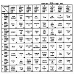
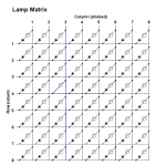
Most of this information is also available in system diagnostics.
Note: Lamp columns and rows are not wired in the same order as they are shown on the lamp matrix. For example in column 5 the physical wire might go from “Thing” to “Light Extra Ball” to “Raise the Dead.”

Each column of lamps is connected by a colored wire running from one lamp to the next. The same is true of each row. The columns use a yellow wire with a colored stripe (for example, yellow-red for column 2). The rows use a red wire with a colored stripe.
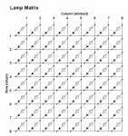
Each lamp has an associated blocking diode as shown in Image 2. Since current can flow in only one direction through the diode, the result is isolation of the lamp. If this isolation is lost (caused by a reversed or shorted diode) the lamp matrix will exhibit bizarre behavior.
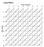
The PDB (power driver board) constantly sends a pulse (or strobe) across the eight columns. This sensing happens at a rate of 500 pulses per second. So at 2ms column 1 is pulsed, at 4ms column 2 is pulsed, etc. This same timing is used when controlling the return lines.
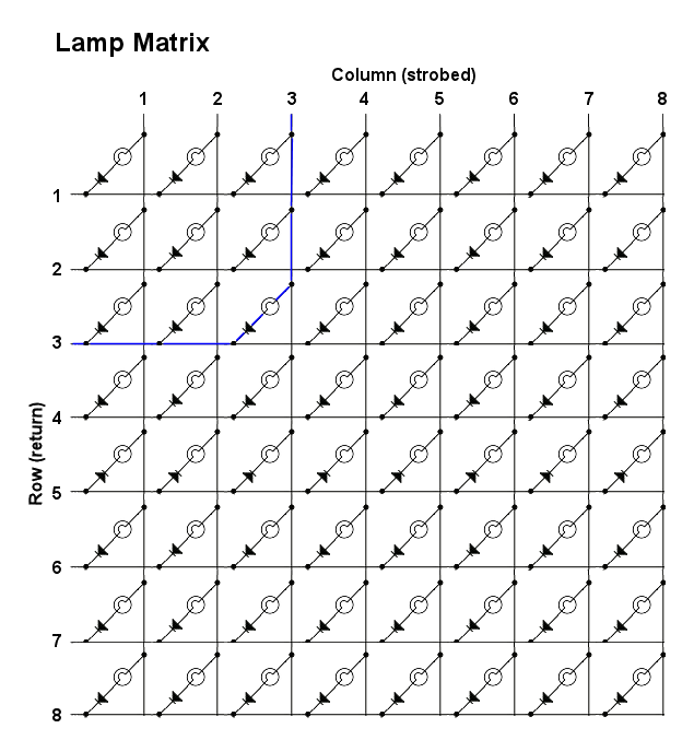
If the row 2 return is taken low at 2ms (providing a path to ground), the lamp in column 1, row 2 lights up. If the CPU wants to turn on the first E in GREED, it will close the circuit for row 3 at 6ms. Since one side is now supplying power and the other ground, the lamp will light (see Image 3).
The lamp circuit uses an 18 volt supply, but since it is pulsed it will read around 12 volts with a DMM. For this reason, when troubleshooting the lamp matrix circuit you should use a logic probe or oscilloscope.
All testing should be done using the row, column or single lamp diagnostics. It’s easy to miss relationships between rows and columns when in game mode.
Troubleshooting the Lamp Matrix
There are few common problems you will come across with the lamp matrix.
- I recently worked on the game, or it’s new to me, and there are lamp problems.
- Controlled lamp fuse keeps blowing.
- A column of lamps are not working.
- A row of lamps are not working.
- Two or more consecutive, but not all lamps, in a column or row are not working.
- Row of lamps always on.
- Every lamp in a column turns on a second lamp in the same row, but a different column.
Human Error

Before troubleshooting any problem, the first question to ask yourself is if you have recently done any work on the game. Or if the game is new to you and has problems, never rule out mis-wiring by the previous owner.
If after replacing a diode/switch you have lamps lighting when they shouldn’t be the diode or the wiring is reversed. Check your setup and make sure the band on the diode is oriented towards the red wire (see Image 1).
An entire column is locked on or not working. The column driver is extremely vulnerable to a short from flasher/solenoid power. Flasher and solenoid voltages can take a while to go to zero, so damage can occur even after powering off the game.
If one of these voltages does contact a lamp, then as soon as the column driver (ULN2803) scans it, it overloads and fuses. Flasher/solenoid voltages can blow through the ULN2803 and take out the 74LS374 that drives it.
And as always check all connectors and then check them again.
Controlled Lamp Fuse Keeps Blowing
This problem can be caused by a short in BR1 (WPC) or D11-14 (WPC-95) or a short under the playfield. Test the bridge/diodes with your DMM in diode/continuity mode and remove the column connector to identify if the issue is playfield short. If it is a playfield short, test each column wire with your DMM for a short to ground.
If that’s all OK, then check each of the column drivers with a DMM in voltage mode. You should get 6-12 volts, if any read higher (approximately 18 volts) then that circuit is locked on (staying high instead of being pulsed). You can also test each column for a pulsed signal using a logic probe.
First test the the TIP107 with a DMM in diode continuity mode for a short (or test with a logic probe). If the transistor is good then the problem lies with either the ULN2803 or the 74LS374. Get your logic probe out and starting at the connector work back through each test point to find where the pulse is getting lost.
Note: The column test point readings in the manual are for use with an oscilloscope or logic probe, not a DMM.
Column Not Working
First we’ll cover a column of lamps not working, and the first question we need to answer is whether the problem is on the playfield or the circuit board. The simplest test is to connect one lead of your DMM, while in diode/continuity mode, to the column wire under the playfield and the other to where the column connector is soldered to the circuit board.
You can also use the jumper/bulb method described at the end of this article.
Note: Test to the board not just to the connector since you could have a bad connector. If we use Addams Family as an example, and column 3 is out, we can see from the manual (see Image 1) it’s a yellow-orange wire and the connector is J137pin 3. While you’re at it, also test from the strobe wire to ground just to make sure there’s not a short.
If you don’t get continuity between the column wire and the board, check the connector and the last section of wire that runs from the playfield to the connector. If you read a short to ground start tracing the wire from beginning to end looking for a short to ground.
If both tests read good, you’ve got a board problem.

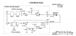
If your problem is on the board, it’s a fairly simple circuit, although different manufacturers use slightly different designs. Some will use a transistor as a driver and others will use an inverter or buffer. Image 4 shows the lamp matrix circuit for an Addams Family.
Get your logic probe out and starting at the connector work back through each test point to find where the pulse is getting lost (it’s staying low). Do this while in test all lamps diagnostic mode.
Note: The column test point readings in the manual are for use with an oscilloscope or logic probe, not a DMM.
Row Not Working
The first part of troubleshooting the return circuit is the same as above, use your DMM to test to the circuit board and ground or use the jumper/bulb method. If the problem is on the playfield, troubleshoot as above.
If the problem is on the power driver board (see Image 4), get your logic probe out and starting at the connector work back through each test point to find where the pulse is getting lost (it’s staying high). Do this while in test all lamps diagnostic mode.
Note: The column test point readings in the manual are for use with an oscilloscope or logic probe, not a DMM.
Partial Column or Row Failure
The only way you can get a partial row or column failure is a broken wire, open diode (or cracked lead) or a problem with a lamp board.
If any of these problems exist, the lamps before the problem will work and the lamps after the problem will not work. Use lamp diagnostics to turn on a column or row while following the wire downstream (the manual, or diagnostics will give you the wire color) until you find the point where the lamps quit working.
Somewhere between the non-working lamp and the last working lamp the wire is broken, there’s a bad connection, the diode is open, or it’s lead is cracked.
If all of the bulbs on a lamp board are out, the most common problem is cracked header pins on the board. If a single lamp on a board does not work, check the tension on the lamp socket and the lamp’s diode. If both are good then re-flow (and build-up slightly) the solder pad for the lamp socket.
Row of Lamps Always On
This problem exhibits as a row of lamps that are always on when in game or attract mode. There are two possible causes: a short to ground in the playfield wiring for that row, or a problem with the lamp matrix row circuitry.
First disconnect the row connector and see if the problem goes away. If it does not go away then check the row looking for a wire that is pinched against a metal part or a diode/lamp socket that is bent and touching ground.
If removing the row connector solves the problem then the row line is being held low rather than being pulsed. Get out your logic probe and starting at the connector work back through each test point to find where the pulse is getting lost.
Note: The column and row test point readings in the manual are for use with an oscilloscope or logic probe, not a DMM.
Every lamp in a column turns on a second lamp in the same row, but a different column.
This problem is caused by a short between two columns, the column driver staying high (rather than pulsing) or a shorted/reversed diode.
For example, if column 1 also turns on a lamp in column 3 and column 3 also turns on a lamp in column 1–and the rest of the columns work fine–there is a short between columns 1 and 3. Disconnect the column connector and test continuity between the two suspect columns on the male board connector and then the female playfield connector. If the former reads a short there is a board problem and if the latter reads a short there is a short in the playfield wiring.
If multiple columns turn on the same row lamp in another column then the problem is either with the column driver or a shorted/reversed diode. Note: The column with the shorted/reversed diode, or the column staying high, will always be the column that has bulbs that come on when they shouldn’t. Additionally, the problem column will not turn on lamps in any other columns.
First, check all columns with a logic probe to see if it they are being pulsed. If a column is staying high then with your logic probe start at the connector and work back through each test point to find where the pulse is getting lost.
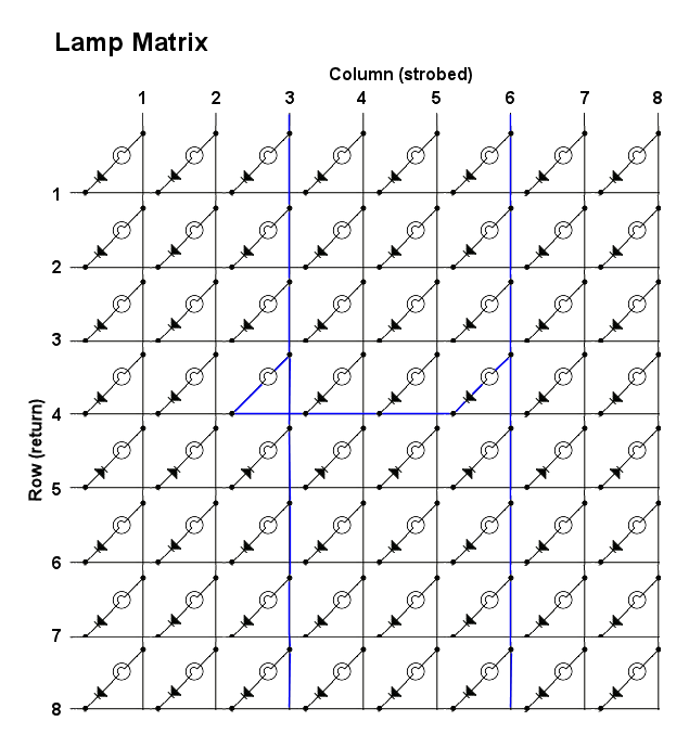
If all of the columns are being pulsed then the problem is likely a shorted/reversed diode.
In Image 5 the diode in column 3, row 4 is shorted and you can see when column 6 is pulsed, column 3 is also illuminated (the blue line). For the sake of clarity I have not highlighted the return side of the current flow. In this example, you would need to test all the diodes in column 3.
Testing with Jumper and Bulb
Caution: Do not use this, or any, jumper method unless you know what you are doing. It not uncommon for beginners to cause severe circuit board damage by shorting pins or applying high voltage to a low voltage circuit.
The following procedure requires a jumper cable with a 1N4004 diode and a bulb or LED installed inline (install the un-banded side of the diode towards the bulb or LED). For the jumper cable I recommend either a mini-grabber (also called mini-clip) or a .1″ female to female jumper. You can get the latter at Fry’s Electronics in a variety of lengths, but 6″ works well.
The connector and bulb info are for Addams Family (use Image 1 as a reference), but you can use this procedure with any machine. Just check the manual to identify your row connector and column connector, the pins for each row and the column and the lamp numbers.
 Note: J133, J134 and J135 (row) are electrically the same and the connector may go to either one. The same is true of the two column connectors, J137 and J138.
Use the following procedure to test.
- Remove J133 (row) and J137 (column).
- Turn on the game and start All Lamps Test.
- Put the end of your jumper with the banded side of the diode on pin 1 of J133.
- Place the other end of your jumper on pin 1 of J137.
- The lamp should flash, which confirms row 1 and column 1 are good.
- Continue, using the pins on the right, which will test all columns and rows.
[Editors note: The following video is about switch matrixes, but much is applicable to the lamp matrix.]
Addendum – Our Experiences
The following is from homepinballrepair.com and does not represent the original author.
Hurricane Williams WPC Lamp Matrix
We had issues with the lamp matrix in a Williams Hurricane. Several of the lamps would light when they were not supposed to.
We followed the procedure outlined above. Graphically, it is helpful to make a copy of the matrix (lamp or switch) to outline the problems.
We tested every lamp individually using the tools in the Test Menu. We graphed the results in a copy of the lamp matrix. We found four ‘nodes’ on the matrix. After inspecting the wiring, we (eventually) realized that the wire to one lamp, one of the ‘nodes’, was soldered to the wrong side of the diode, in effect taking the diode out of the circuit. Moving the wire to the correct side fixed the problem.
Conclusion
When troubleshooting a lamp matrix problem, the biggest waste of time is to stop and look at all the lights. Following this systematic procedure, print out the matrix and then test each one in the menu, will cut troubleshooting time dramatically, making complex problems seem simple.
Editors Notes and Comments
We reproduced the original page from TerryB and (late, lamented) PinballRehab.com because we found it amazingly useful and have referred to it over and over again over the years.
Comments, including suggestions, improvements, errors, etc. are welcome (see below).
If you have a specific question about your game that does not directly apply to matrix troubleshooting, please see our FAQ section.