B. Fliptronics?
Fliptronics flipper or ‘Old Style’?
C. Rebuild Old Style Flippers
1) Order Parts
2) Disassembly
3) Flipper Bat
4) Adjust EOS Switch
E. Rebuild Fliptronics Flippers
E. How To
1) Steps Involved
2) Install EOS Switch
3) Flipper Bat
4) Adjust EOS Switch
F. Upgrade To The Best Flippers
G. How Solid State Flippers Work
1) Fliptronics
2) DE/Sega
3) Sega/Stern Whitestar
H. External Links
Cautions: Must read before proceeding. Machine must be turned off and unplugged.
A glossary of terms used on this page.
Introductory WPC flipper information for first timers. If this is you, please read this.
Note: Click on any image or links for a larger image.
Tools Needed

1) Screwdriver (Phillips and occasionally slotted)
2) Allen Wrenches – usually 5/32″
3) Needle Nose Pliers
4) Wire Cutters
5) Soldering Iron & Solder
6) Nut Drivers and/or socket wrenches. 3/8″ socket to remove the flipper bat.
7) Soldering iron and solder.
Optional:

Flipper gauge – Nice to have, especially when doing this the first time.
Shrink Tubing (or similar) – To insulate the EOS switch capacitor leads (not used on Fliptronics).
Wire stripper (or similar) – This is our favorite model.
Wire – #18 gauge stranded is preferred.
WPC Fliptronics or WPC ‘Old Style’?
Games with Old Style pre-Fliptronics Flippers
| Funhouse | 1990 |
| Harley-Davidson | 1991 |
| Bride of Pin*Bot | 1991 |
| Gilligan’s Island | 1991 |
| Terminator 2 | 1991 |
| Hurricane | 1991 |
| The Party Zone | 1991 |
If you have one of these games, move down to ‘Rebuild WPC Old Style’.
Old style flippers have a couple of problems. We suggest upgrading the old style flippers.
All other Bally / Williams WPC games use Fliptronics flippers.
Rebuild Old Style WPC Flippers
Parts Needed
The easiest way to rebuild a flipper is to order a flipper repair kit (Pinball Life or Marco) from a pinball parts supplier.
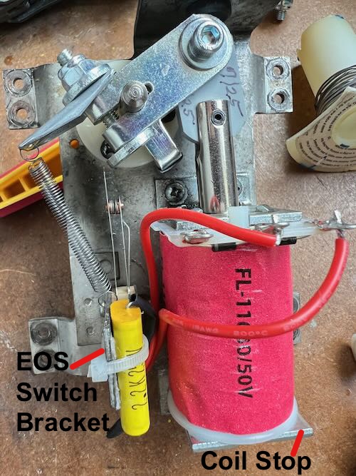
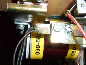
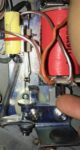
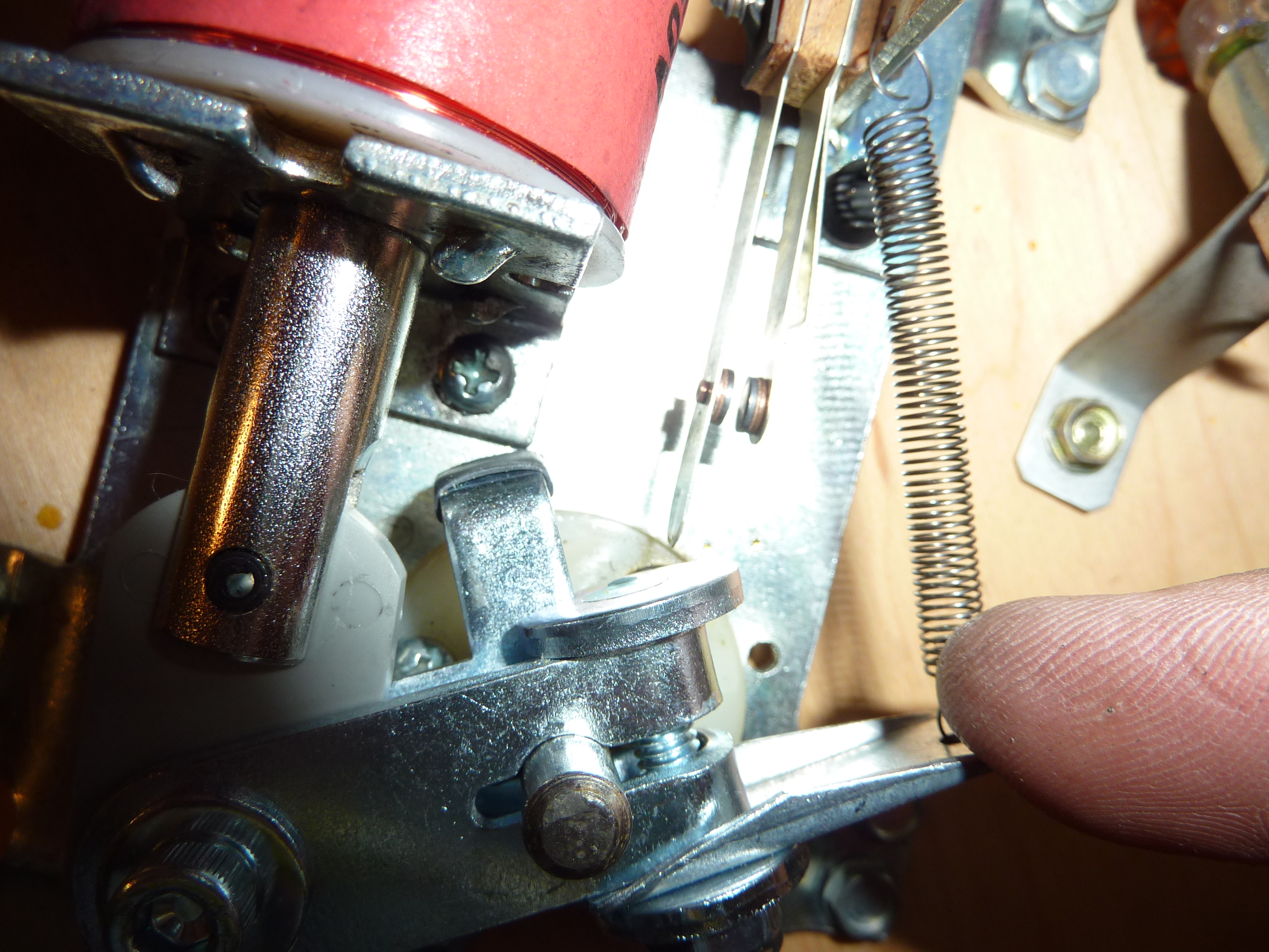
Before you order a kit, are the diodes on the coil facing aways from the coil stop?
If the diodes are facing as shown in this photo, you can just order the kit.
If the diodes are facing the coil stop, skip onto this page.
If you want to upgrade to the exterior spring, also see this page.
Rebuilding
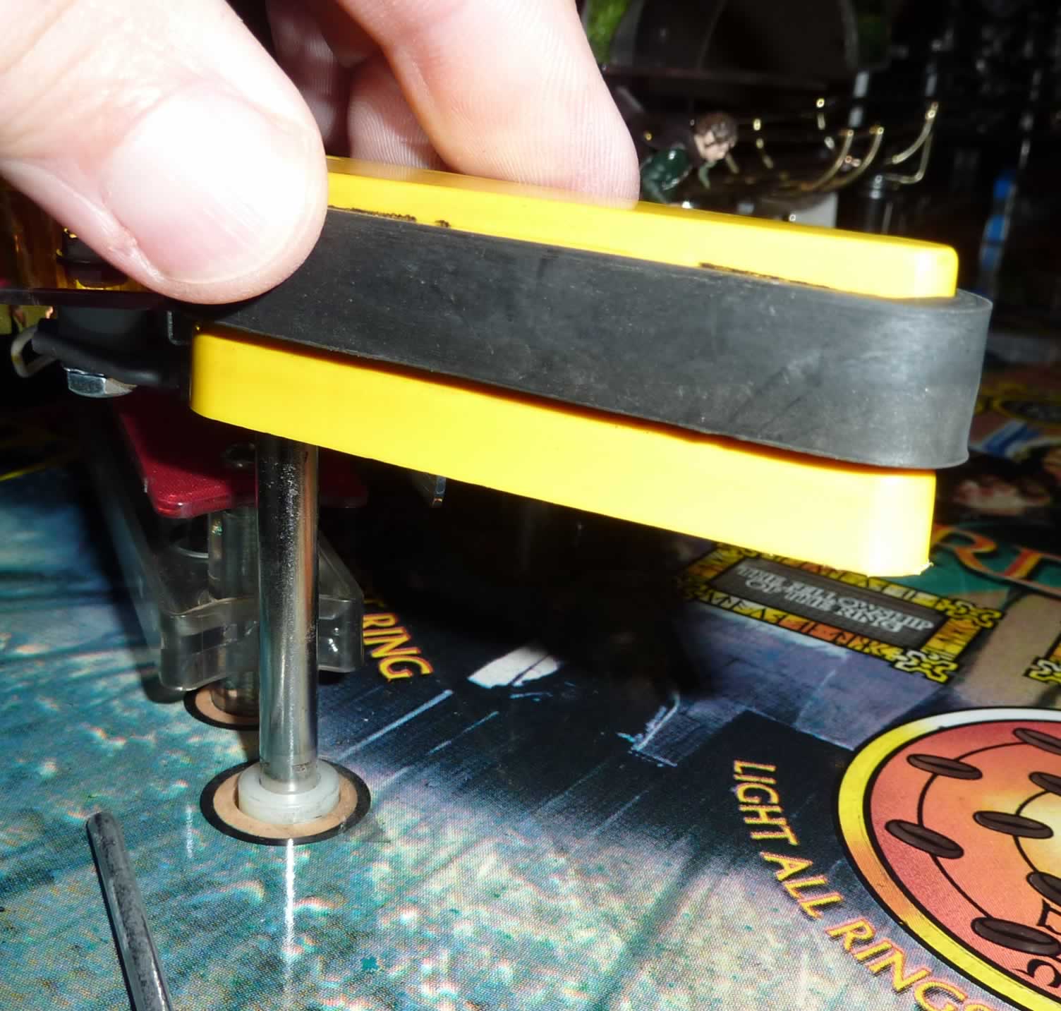
Pull up and down on the flipper itself. Notice that there is a small amount of vertical movement. When re-assembling, it is crucial that there be a little bit of up and down movement on the flipper bat, or the mechanism will bind.
Steps: Caution: Insure the machine is turned off and unplugged.
 1) Remove the flipper by loosening the nut holding the flipper bat shaft. Use a 3/8″ socket or box wrench.

Note: At this point, it is possible to unsolder the two wires coming from the playfield wiring harness to the coil and remove the entire flipper assembly. This makes it much easier to rebuild the flippers. If doing so, take photos to insure that these two wires are soldered to the same tabs on the coil. Wiring backwards will cause a short.
2) Remove the flipper coil stop using a 5/32 Allen wrench.
3) The solenoid coil and crank assembly will no longer be held in place. Remove the coil from the plunger.
4) Remove the spring and the crank assembly.
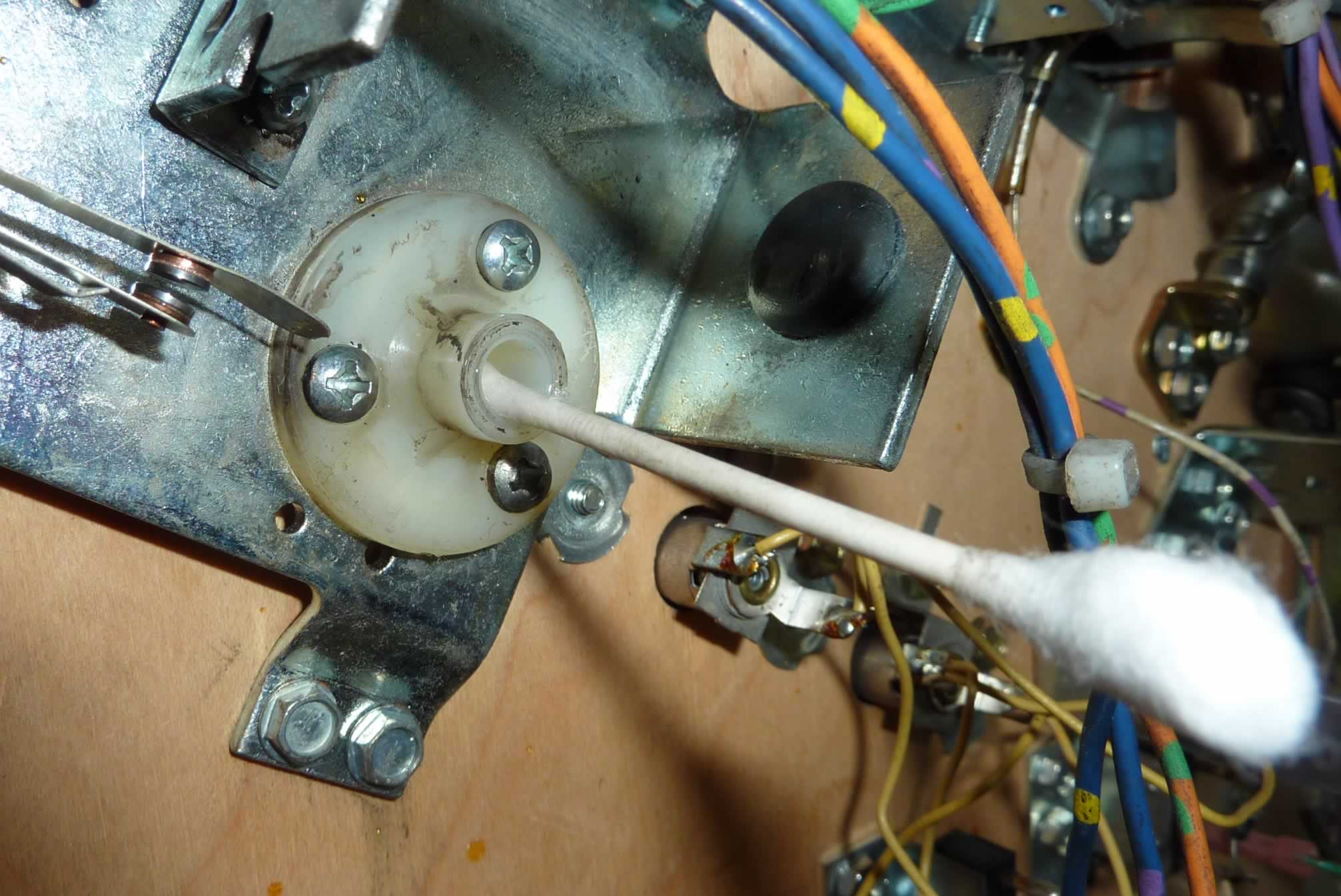
5) Clean out the bushing hole for the flipper shaft. We use several q-tips or a towel and small amounts of isopropyl alcohol.
6) Inspect the diodes on the coil. Carefully insert a small screwdriver behind the diode and push slightly to see if it is broken. If one is broken or suspect, replace it. Use 1n4007 (best!) or 1n4004 (OK).
7) Replace the coil sleeve.
It maybe impossible to remove some sleeves. That is usually because the coil overheated and is ruined. If so, replace the coil and use a new sleeve.
The coil sleeve end with the collar goes towards the coil stop.
8) There is a left and right crank assembly. Compare the new ones with the one you have removed and select the identical one. Attach the new spring to the EOS switch bracket and the linkage.
Here is the only tricky part – insert the crank assembly through the solenoid bracket, then into the coil (diode / wire end towards the crank assembly.
Hold all three parts together and insert the coil into the new coil stop from step #2. While holding this all together, manipulate the crank assembly into its proper position so that it is ready to be connected to the flipper bat shaft. If this assembly had a spring on the plunger, be certain to install it prior to inserting the Crank Assembly into the coil.

9) If the original coil stop had a washer / spring attached, set it on the new one. Attach the new coil stop, removed in step #2, to the base plate. At this point, all components should be held into place.
Replacing the EOS Switch – Soldering Iron Required
Types of EOS Switches:

a) Simple high current switch made of tungsten
b) Complex high voltage switch (see Bally linear flippers, above) which includes an upper flipper switch (tungsten) or a lane change switch (low power)
c) Simple low voltage switch (usually ’92 and later).
Types a) and b) are closed when not in use. In b), the upper flipper or lane change part of the switch will be open.
Type c) will be open when the flipper is not in use (normally open) in the Williams / Bally Fliptronics pins. In other pins, like DE/Sega/Stern, EOS switches are low voltage, but are closed when the flipper is not in use (normally closed).

Note: If there are two switches on the flipper, it is crucial that they be wired exactly the same way and physically in the same location on the bracket. The NC EOS switch must open when the flipper is activated. And the NO second switch must close when the flipper is activated.
Note: We found some EOS switches have an oil on it that must be removed for the flipper to have full power. A Q-tip and Isopropyl Alcohol on the contacts will quickly do the trick.
10) Note the orientation of the EOS switch, which side faces the coil and which leaf is hit by the flipper as it opens. Remove the screws holding the switch. Leave the old switch dangling by the wires.
11) Mount the new EOS switch in the same orientation as the old one. Tighten the screws firmly.

12) One at a time, unsolder the wires from the old switch and attach them in the same place on the new switch. If there are only two wires, location is not crucial. But if it is a multilevel switch, it is crucial that the wires be connected to the same tabs.
Make absolutely certain that none of the wires from the EOS switch are touching or shorting anything else. On many systems, these wires carry high voltage and can fry other components.
Many flippers starting around 1988 to 1992 (pre-solid state / Fliptronics) had parallel coils and had capacitors connected to the EOS switches. These capacitors were installed to reduce arcing and extend the life of the switches. Check your manual. If your manual to see if a capacitor is required. Parallel coil flippers that are not solid state computer controlled require a capacitor.
The capacitor can be installed in either direction.
If you removed the assembly from the playfield, reinstall it now and solder back the wires.
13) Insert the flipper bat shaft through the playfield and into the crank assembly. Tighten the shaft so that it is secure, just enough that it cannot fall out.

Do not tighten fully. We will align the flipper in later steps. If you have a flipper gauge, you can use it here. Or save it for later in the final alignment steps.
14) If spring is outside the plunger, attach it the other end to the bracket. Needle nose pliers make this step easier.
Tightening the Flipper Bat
At this point, the flipper bat shaft should be firmly, but not tightly, connected to the crank assembly in step #13. Check its position in the playfield. It should be possible to swing the flipper bat into various positions.
15) While holding the flipper mechanism in the closed (at rest – power off position) below the playfield, swing the flipper bat above the playfield. If the bat turns too freely, tighten the screws or bolts holding the shaft in place. If it is difficult to turn, loosen these screws or bolts just a little. Make certain that there is a little up and down movement. Use the Flipper gauge if you have one.

16) Swing the bat into the desired position. If there are small markers in the playfield, the bat should either point at the marker, or rest on it. If the alignment point is below the flipper, insert a toothpick into the marker and set the bat against the toothpick (without the rubber). If no markers are present, set the bat parallel to the wire on the playfield.
17) Tighten the bolt / screws on the crank assembly. If after a few minutes of game play, the flipper bat starts to shift position, it was too loose.
It is possible to over tighten the type with a bolt (Williams WPC). Some people will crank those so hard, that the two pieces bend and touch each other – don’t do that.
Flipper shafts held in place by one or more Allen wrench screws usually have an indent in place, making fine adjustment difficult. If so, switch the left and right flippers and make a new indent. Or replace the flipper bats & shafts.
Adjusting the EOS Switch
| 18) Crucial: Check the EOS switch adjustment. For non-Fliptronics pins, the EOS switch must open when the flipper is activated (up). The EOS switch should open as late as possible so that full power goes to the flipper as long as possible. But the switch must open completely or the coil will burn and/or arcing will occur and ruin the EOS switch. Nominally, the EOS switch should open ~ 1/8″, but we do this by eye. |
If you are new to adjusting EOS switches, please consult our guide. Note that the stationary leaf must hold the inner leaf in place. When the EOS switch closes, the two leafs must be pushed together.
It is crucial to get this adjustment correct, or your flippers will not operate properly.
Fliptronics
Williams/Bally computer controlled Fliptronics flippers in the early 1990’s. All machines from The Addams Family on were Fliptronics. This also includes WPC-S and WPC95 machines.
Bally / Williams Fliptronics machines have EOS switches that are normally open, then close when the flipper is activated. These switches carry low power and should never be filed. These are gold plated.
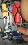
The EOS switches can be cleaned by inserting a business card and dragging it across the contacts as they are held closed by your fingers. Or they can be cleaned with Q-tips and a small amount of 91% isopropyl (not rubbing) alcohol (Note: flammable – see cautions).

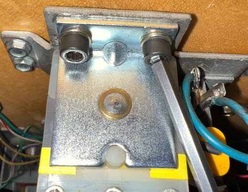
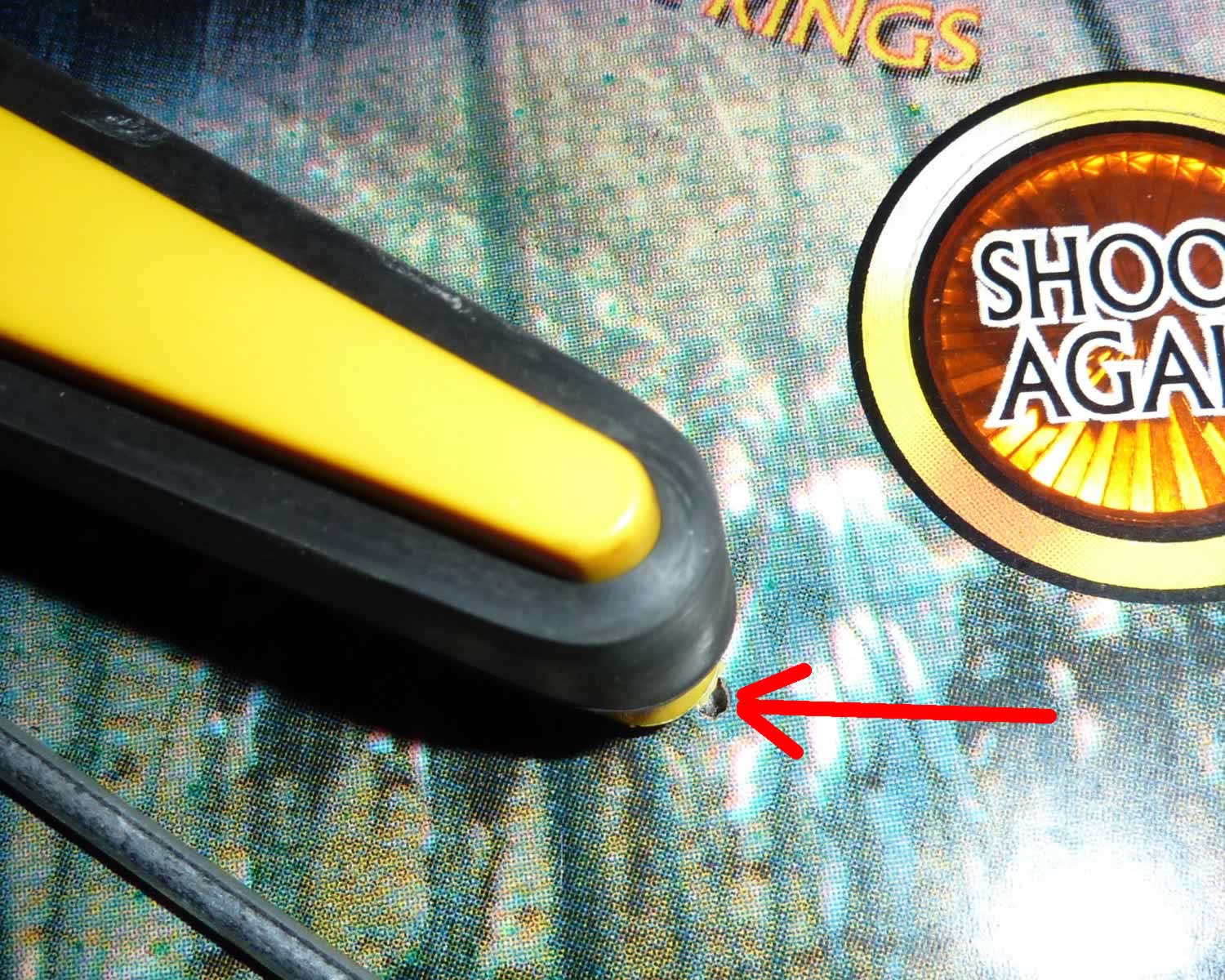
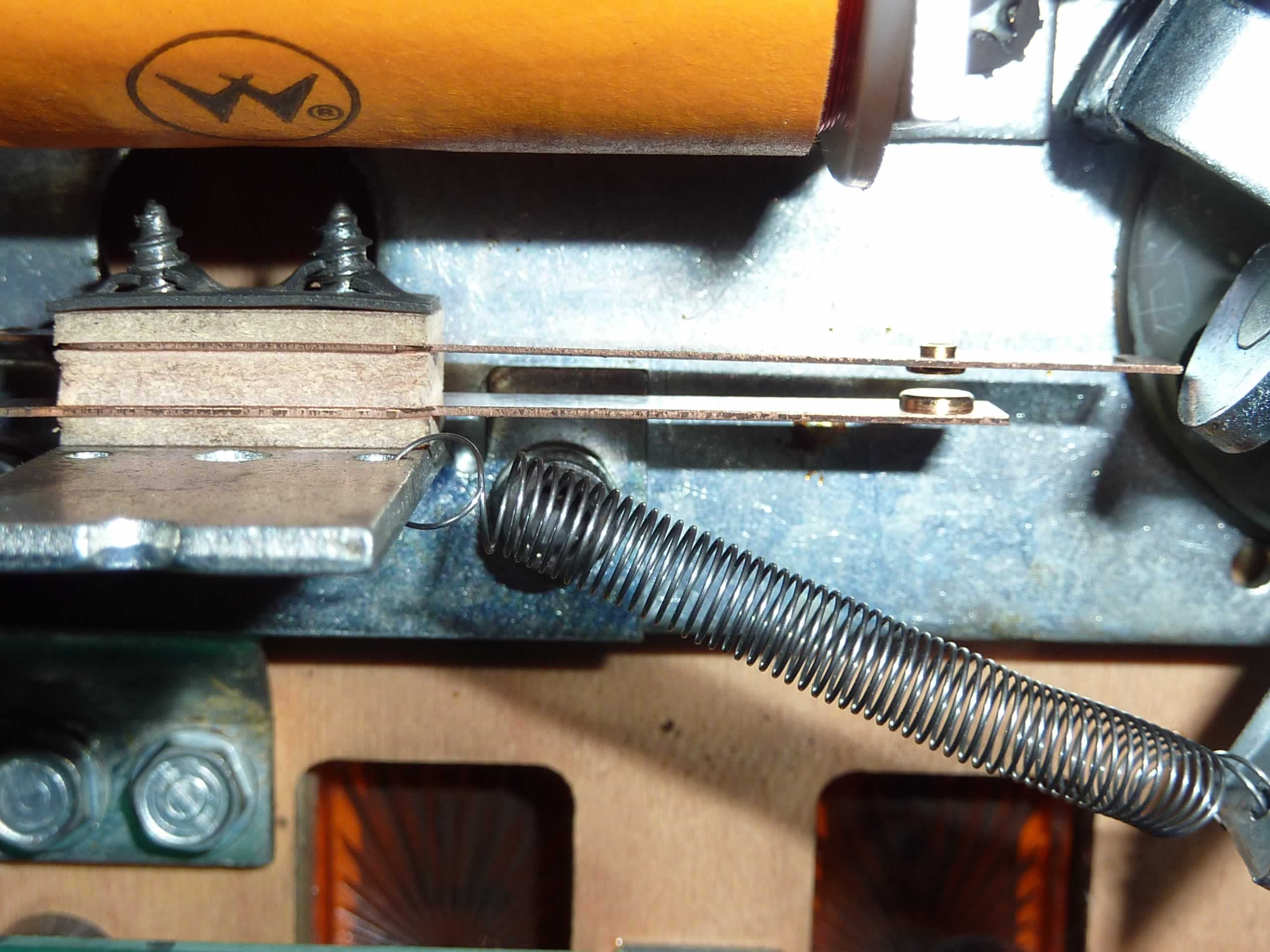
Note (in the picture) that this low power EOS switch shows almost no wear. It belongs to a Williams / Bally Fliptronics pin. These are recognizable because the switches are open when the flipper is at rest. These switches can last longer than the linkage.
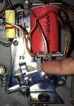
This (see photo) is a flipper switch for an early fliptronics game such as The Addams Family. Some fliptronics games used optical switches on the flipper buttons that do not have metal contacts.
How To Rebuild WPC Flippers
Prior to beginning disassembly, pull up and down on the flipper itself. Notice that there is a small amount of vertical movement. When re-assembling, it is crucial that there be a little bit of up and down movement on the flipper bat, or the mechanism will bind and not swing freely.
Steps: Caution: Insure the machine is turned off and unplugged.
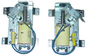
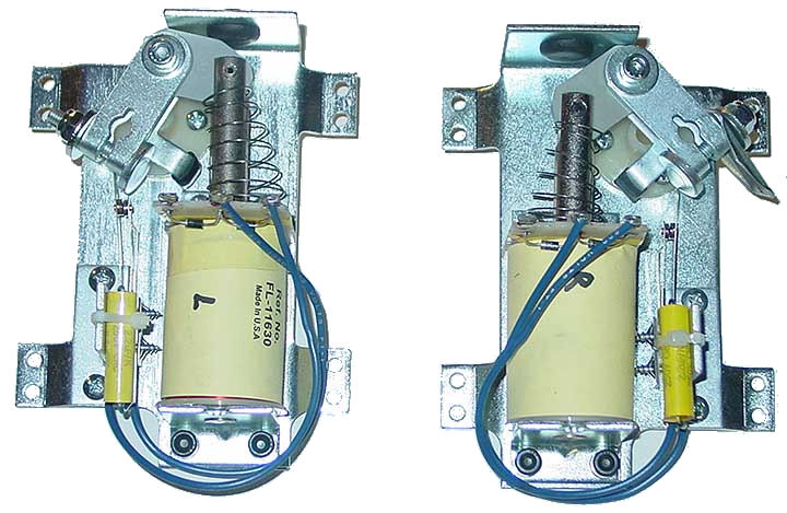
1) Remove the flipper by loosening the nut holding the flipper bat shaft. Some flippers are held in place by two set screws and an Allen (hex) wrench is required. Others are held in place by a combination of a nut and an Allen bolt like the Williams assembly to the right. Some require only a socket wrench to loosen.
Note: At this point, it is possible to unsolder the two wires coming from the playfield wiring harness to the coil and remove the entire flipper assembly. This makes it much easier to rebuild the flippers. If doing so, take photos to insure that these two wires are soldered to the same tabs on the coil. Wiring backwoods will cause a short.
Note: With Fliptronics flippers, the two small wires going to the EOS switch will also have to be unsoldered.
2) Remove the flipper coil stop (#1 in the above ‘Components‘). This will require an Allen wrench.
3) At this point, the solenoid coil and crank assembly will no longer be held in place. Remove the coil from the plunger and let it hang by the wires (unless you unsoldered the wires).
4) Use your needle nose pliers to disconnect the spring from the base.
5) Clean out the bushing hole for the flipper shaft. We use several q-tips or a towel and small amounts of isopropyl alcohol. Some kits include a new bushing. Note, if the flipper dragged on the playfield, likely cause was this worn bushing. Replace it. Most of the time, this bushing does not require replacement.


6) Inspect the diodes on the coil. Carefully insert a small screwdriver behind the diode and push slightly to see if it is broken. If one is broken or suspect, replace it. Note that some coils have two diodes, others just one and some do not have any at all.
7) Replace the coil sleeve. Check to see which end of the coil has the sleeve with the collar. Press out the sleeve from the other side, then insert the new one with the collar on the same side. It maybe impossible to remove some sleeves. That is usually because the coil overheated and is ruined. Replace the coil and use a new sleeve.
8) There is a left and right crank assembly. Compare the new ones with the one you have removed and select the identical one. Attach the new spring to the EOS switch bracket and the linkage.
Here is the only tricky part – insert the crank assembly through the solenoid bracket, then into the coil (diode / wire end towards the crank assembly.
Hold all three parts together and insert the coil into the new coil stop from step #2. While holding this all together, manipulate the crank assembly into its proper position so that it is ready to be connected to the flipper bat shaft. If this assembly had a spring on the plunger, be certain to install it prior to inserting the Crank Assembly into the coil.
9) If the original coil stop had a washer / spring attached, set it on the new one. Attach the new coil stop, removed in step #2, to the base plate. At this point, all components should be held into place.
Replacing the EOS Switch – Soldering Iron Required
Types of EOS Switches:
a) Simple high current switch made of tungsten
b) Complex high voltage switch (see Bally linear flippers, above) which includes an upper flipper switch (tungsten) or a lane change switch (low power)
c) Simple low voltage switch (usually ’92 and later).
Types a) and b) are closed when not in use. In b), the upper flipper or lane change part of the switch will be open.
Type c) will be open when the flipper is not in use (normally open) in the Williams / Bally Fliptronics pins. In other pins, like DE/Sega/Stern, EOS switches are low voltage, but are closed when the flipper is not in use (normally closed).
Note: If there are two switches on the flipper, it is crucial that they be wired exactly the same way and physically in the same location on the bracket. The NC EOS switch must open when the flipper is activated. And the NO second switch must close when the flipper is activated.
Note: We found some EOS switches have an oil on it that must be removed for the flipper to have full power. A Q-tip and Isopropyl Alcohol on the contacts will quickly do the trick.
10) Note the orientation of the EOS switch, which side faces the coil and which leaf is hit by the flipper as it opens. Remove the screws holding the switch. Leave the old switch dangling by the wires.
11) Mount the new EOS switch in the same orientation as the old one. Tighten the screws firmly.
12) One at a time, unsolder the wires from the old switch and attach them in the same place on the new switch. If there are only two wires, location is not crucial. But if it is a multilevel switch, it is crucial that the wires be connected to the same tabs.
Make absolutely certain that none of the wires from the EOS switch are touching or shorting anything else. On many systems, these wires carry high voltage and can fry other components.
Many flippers starting around 1988 to 1992 (pre-solid state / Fliptronics) had parallel coils and had capacitors connected to the EOS switches. These capacitors were installed to reduce arcing and extend the life of the switches. Check your manual. If your manual to see if a capacitor is required. Parallel coil flippers that are not solid state computer controlled require a capacitor.
The capacitor can be installed in either direction.
If you removed the assembly from the playfield, reinstall it now and solder back the wires.
13) Insert the flipper bat shaft through the playfield and into the crank assembly. Tighten the shaft so that it is secure, just enough that it cannot fall out.
Do not tighten fully. We will align the flipper in later steps. If you have a flipper gauge, you can use it here. Or save it for later in the final alignment steps.
14) If spring is outside the plunger, attach it the other end to the bracket. Needle nose pliers make this step easier.
Tightening the Flipper Bat
At this point, the flipper bat shaft should be firmly, but not tightly, connected to the crank assembly in step #13. Check its position in the playfield. It should be possible to swing the flipper bat into various positions.
15) While holding the flipper mechanism in the closed (at rest – power off position) below the playfield, swing the flipper bat above the playfield. If the bat turns too freely, tighten the screws or bolts holding the shaft in place. If it is difficult to turn, loosen these screws or bolts just a little. Make certain that there is a little up and down movement. Use the Flipper gauge if you have one.
16) Swing the bat into the desired position. If there are small markers in the playfield, the bat should either point at the marker, or rest on it. If the alignment point is below the flipper, insert a toothpick into the marker and set the bat against the toothpick (without the rubber). If no markers are present, set the bat parallel to the wire on the playfield.
17) Tighten the bolt / screws on the crank assembly. If after a few minutes of game play, the flipper bat starts to shift position, it was too loose.
It is possible to over tighten the type with a bolt (Williams WPC). Some people will crank those so hard, that the two pieces bend and touch each other – don’t do that.
Flipper shafts held in place by one or more Allen wrench screws usually have an indent in place, making fine adjustment difficult. If so, switch the left and right flippers and make a new indent. Or replace the flipper bats & shafts.
Adjusting the EOS Switch
| 18) Crucial: Check the EOS switch adjustment. For non-Fliptronics pins, the EOS switch must open when the flipper is activated (up). The EOS switch should open as late as possible so that full power goes to the flipper as long as possible. But the switch must open completely or the coil will burn and/or arcing will occur and ruin the EOS switch. Nominally, the EOS switch should open ~ 1/8″, but we do this by eye. |
If you are new to adjusting EOS switches, please consult our guide. Note that the stationary leaf must hold the inner leaf in place. When the EOS switch closes, the two leafs must be pushed together.
It is crucial to get this adjustment correct, or your flippers will not operate properly.
For Fliptronics EOS switch: switch is open when the flipper is at rest. Closes when the flipper is fired. Note that that this is the opposite of what happens with older style full power flippers. Adjustment is so that the switch starts to open as the flipper starts to fall back from fully open. The only purpose for this EOS switch is to tell the computer that a force is pushing the flipper closed (such as trapping 3 pinballs) and the computer increases the power to the flipper. And improperly adjusted EOS switch cannot cause Fliptronics flippers to be weak.
For DE/Sega/Stern EOS switch: if the flipper coil has only two wires, then these flippers are also computer controlled, but the EOS is adjusted like an older style flipper. The EOS should be closed at rest. The EOS will open when the flipper is activated. This EOS works like the Fliptronics, telling the computer that the flipper is being forced closed and to add more power to the coil. And improperly adjusted EOS switch cannot cause DE/Sega/Stern computer controlled flippers to be weak.
If your DE game has three wires, then the flipper is not computer controlled and the EOS switch should be adjusted just like all earlier pinball machines.
If your flipper coil has two switches then the NC (normally closed) switch is the EOS switch. Adjust as above (non-fliptronics). But the second (outside) switch must close. It should close after the EOS switch opens. That way the second flipper does not pull full power while this flipper is opening.
If there is not an upper flipper, then this switch may activate the lane change. Adjustment is not as crucial and the switch just needs to close as the flipper opens.
19) Rebuild the other flipper. When finished, the two flippers should sit at the same angle. Try playing the pin. Readjust the position of the flippers if they seem incorrect to you. I mark the date if flipper rebuilding with a sharpie on part of the metal (not the coil or plunger).
External Links
How a Flipper Works – Steve Kulpa’s great explanation. [Steve’s website is down as of 2020. He has allowed us to reproduce it on our website.]
Parallel vs. Serial Coils – A group discussion on the differences between coils.
Coil Cross Reference – Extremely helpful information about pinball coils and cross references from Pinball Medic.
Copyright 2006 – 2025, all rights reserved.
Comments
Comments, including suggestions, improvements, errors, etc. are welcome (see below).
If you have a specific question about your game that does not directly apply to rebuilding flippers, please see our FAQ section.