Solid State Flippers
B. How Flippers Work
C. Serial Coils
D. Parallel Coils
E. Computer Controlled Flippers
Solid State Flippers
1. Fliptronics
a) How Fliptronics Works
b) The Circuit
c) Optical Flipper Switch
d) Troubleshooting
e) Optical Flippers Controversy
2. DE/Sega
a) The Circuit
b) Troubleshooting
3. Sega/Stern Whitestar
a) The Circuit
b) Troubleshooting
4. Contact Information / Feedback
5. External Links
A More Detailed Explanation of How Computer Controlled Flipper work
Since the beginning of flipper pinball games (1947) the flippers have been a weak point that required chronic maintenance. This made pinball games expensive to maintain and one of the reasons that video games were overtaking pinball in popularity. In the early 1990’s, pinball companies finally found a way to address this weakness through the introduction of computer controlled flippers.
Unlike earlier flippers, only low power traveled through the flipper switches. The EOS switches also had only low power and their function changed so that even if the EOS switches were broken the flippers would continue to work (almost) normally. Finally, optical switches were introduced which may (or may not) be even more reliable than the mechanical switches.
With the introduction of Solid State Flippers, finally the only weakness was the wear and tear of the linkage and the coil stop, plus the dirt issue that never went away.
Additionally, the computers could control the power of the flippers. Stern later allowed operators to adjust flipper power to compensate for wear (and, perhaps make the game harder to beat) and Jersey Jack Pinball introduced weaker flipper power during certain gameplay situations.
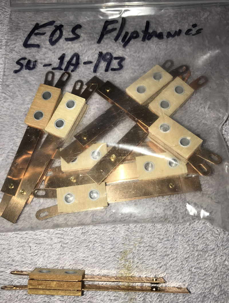
Fliptronics – Williams / Bally WPC

Perhaps the most famous of the solid state flippers is Fliptronics. It was introduced by Williams (WPC – Bally Williams) in 1992 in The Addams Family which had Fliptronics 1 – the only game produced with version 1. All later games have Fliptronics 2. The major difference between these is that Fliptronics 2 has the flipper power supply build in. All WPC games (WPC89, WPC-S, WPC95) from 1992 on have Fliptronics flippers. There are two different Fliptronics 2 boards (A-15472 and A-15472-1) and the difference between them is minor – the 50 V power supply 100uF capacitor C2 is removed in the later versions. These boards can be used interchangeably.

In addition to using low power switches that (almost) never wear out, Fliptronics EOS switches are different in that they start out open (when the flipper is off), then close when the flipper is activated. This is completely opposite of what most people expect and can lead to confusion when replacing and adjusting flippers.
In earlier mechanical flippers, the EOS switch turns on the low power (hold) winding, keeping the flipper open with lower power. With Fliptronics, the EOS switch plays a completely different role. When the switch is closed, the computer knows that the flipper is open all the way and applies only low power. But if a force strong enough to push the flipper backwards – such as capturing two pinballs during multiball – the EOS starts to open. The computer reacts by applying greater force and the flipper then opens back up.

Just like earlier mechanical flippers, all Fliptronics have two coil windings: 1) power and 2) hold.
For WPC89 and WPC-S, the Fliptronics boards are located in the upper left of the backbox. For WPC95 the Fliptronics circuitry is incorporated into the driver board. If confused which version your game is, check the listing in the Internet Pinball Database.
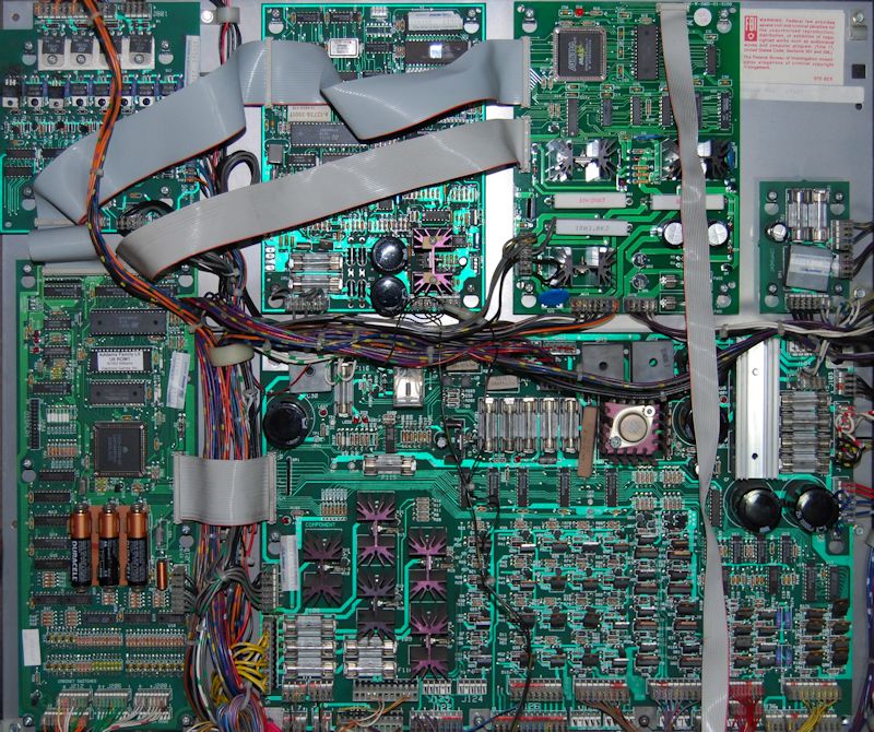
On WPC89 and WPC-S, the flipper switches are wired to the Fliptronics board.
Starting with WPC-95, the Fliptronics circuitry is incorporated into the Power Driver Board and the flipper opto switches are connected to the CPU at J212. The EOS switches are connected to the CPU at J208. WPC-95 also use Schmitt trigger optos for the flipper opto boards.
Each flipper has two circuits, one for power and the second to hold the flipper. The power circuit is more robust than pre-fliptronics in that the TIP102 transistor is a pre-driver for a higher current TIP36. The hold portion of the board has just the TIP102 transistor which should be adequate to hold the flipper open.

Also, the Fliptronics 2 board has a built in (snubber – flyback) diode to protect the transistors from the voltage induced as the coil is turned off (back EMF). In theory, that means that Fliptronics flipper coils do not need to have a diode on the coil. This coil frequently breaks and fails from vibration of the coil opening. However, in practice, all coils used on Fliptronics flippers seem to have these diodes installed.
Fliptronics 1 used in The Addams Family does not have snubber diodes installed on the fliptronics board. A broken coil diode will fry a control transistor.
Installing an aftermarket Fliptronics 2 board in The Addams Family does not use the snubber diodes in the Fliptronics 2 board since the original power supply remains in use, not the power supply in the Fliptronics 2 board.
How Fliptronics Works
 Just like the mechanical design, power is applied to the coils all of the time. The flipper is activated when the coil is connected to ground. In a mechanical flipper, the coil is grounded through the flipper button and the EOS cuts the power back. In Fliptronics, the computer turns on the flipper, then cuts the power back.
When the player hits the flipper button, a signal is sent to the computer to activate the flipper. The CPU communicates through the ribbon cable to the Fliptronics board.
In WPC89 Fliptronics, including WPC-S, the flipper optos are connected to the Fliptronics board. Starting with WPC95 games, the switches are connected directly to the CPU.
Initially, the higher power circuit is turned on. When the computer receives the signal that the EOS switch closes, the computer turns off the power circuit and energizes the hold circuit. If the computer never receives a signal from the EOS switch, the computer times out the power circuit and energizes the hold circuit. This allows the flipper to work almost normally even if the EOS switch is broken.
The Fliptronics Circuit

The Fliptronics board has circuits to control up to four flippers. If a game has less than four flippers, some of the circuity is not used and could be used to control other features such as magnets.
Each of the four circuits have two parts: 1) power and 2) hold. The power is used initially and only briefly. Since the coils draw a large amount of current during the power surge, a second more powerful transistor, a TIP36C is used. The TIP36C is controlled by a TIP102 – the same transistor that controls other game coils. The TIP102 is controlled by a 2N4403 pre-driver, which is in turn controlled by an IC U2 74374.
IC U2 is then turned on via U5 which is activated by the flipper switch. Then the CPU turns off the power circuit and turns on the hold circuit, as long as the player holds the flipper button.
While the EOS switch is not as important, it does play a roll. If enough pressure is placed on the flipper, such as catching several pinballs during multiplay, the hold circuit may not have enough power. The flipper then starts to close, the EOS switch opens up and the computer turns back on the power circuit long enough to hold up the flipper.
The Optical Flipper Switch
Williams decided to replace many of the mechanical switches with optos. Initially, these optical switches were more reliable and did not require adjustment. But these pins were manufactured decades ago and the LED transmitters get weak and burn out. Additionally, the optos get dirty and occasionally the receiver goes bad. Additionally, Williams used a wavelength of LED that is less reliable than the optos used today.
The original optos used basic phototransistors that, along with fading transmitters (LEDs) can lead to gradual degradation. This leads to potential problems with flipper opto switches including weak or stuttering flippers.
Replacement flipper optos have Schmitt trigger phototransistors. These have the advantage that they work until they fail. Williams started using these in WPC95 games.
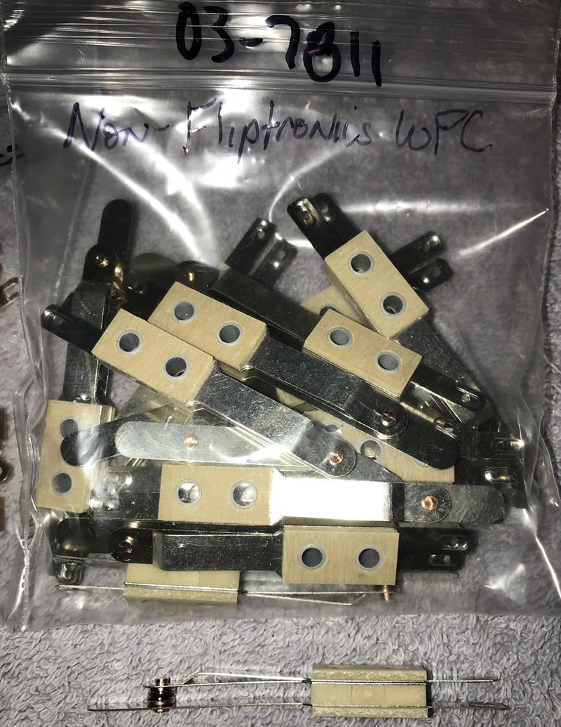
Mechanical flipper switches are easy to diagnose and replace. Many owners have removed the optical flippers and replace them with mechanical switches.
Weak or Non-Working Flippers
When Fliptronics flippers are weak, the problem is almost alway mechanical – rebuild the flippers. Other issues can cause flippers to be weak. They are:
1) The power supply. Check each tab on the coil to insure that +50 VDC is present. Note that this may test as high as +70 VDC because the power is not under load. If voltage is low, it is possible that the bridge rectifier on the power supply is bad.
2) Connectors and solder points. Each connector and solder point has the potential to act as a resistor and sap the power. For WPC89 and WPC-S, the AC power comes into J901 and out J907. Look for burned or damaged connections and poor solder on the header pins on the board. The power to each flipper is daisy chained. Look for strands of wire broken. The power then comes back into the Fliptronics board at J902, another potential problem.
3) The coil can be damaged. Check and compare resistance of each coil (power off!) to the others. Unplug J902 and J907 before testing resistance. Check both the power and hold sections separately. Unlike non-Fliptronics flippers, the EOS switch does not short the hold portion of the coil.
4) If the flipper does not work at all, try momentarily shorting the tab of the TIP102 (not TIP36C) transistor, for the power circuit, to ground. If it does fire, then the TIP102 might be bad. If it does not work, the TIP36C might be bad.
5) If the flipper does not fire when shorting the TIP102 to ground, try momentarily shorting the wire at the connector to the Fliptronics board. If it fires, then it is likely that the TIP36C is bad. If it does not fire, then it is a wiring or power supply problem.
If replacing the TIP36C, it is a good idea to replace the TIP102 also.
Optical Flipper Controversy
 The optical flipper board caused my weak flippers. Cleaning the opto flipper board made the flippers stronger.
The opto flipper board is digital. It is either on or off. The opto flipper board cannot (?) cause weak flippers. At least not than we can figure out – yet experienced pinball repair people continue to insist that opto flippers swithes can cause weak flippers.

The flipper switch optos feed to an IC LM339. LM339 either turns on or off. It cannot turn partially on. As a test, we installed a variable resistor (a ‘pot’) on the output of the opto flipper board. We adjusted the signal down until the flipper stopped working. We then slowly increased the signal. At one point, we could get the flipper to ‘twitch’. But above that, the flipper worked perfectly. Below it did not work at all. At no point were we able to get a ‘weak’ flipper.
Technical mumbo jumbo: However, the LM339 circuitry does not include hysteresis circuitry. This means a weak opto in the flipper board might not completely turn on the LM339 which, instead, might send out pulses. This would explain why a weak flipper board opto might cause weak flippers and/or hot coils.
WPC95 games use Schmitt trigger optos that have hysteresis built in.
I replaced the flipper board, or cleaned the optos and my flippers are stronger!
It could be that your old flipper boards were weak enough to cause hysteresis. Your new boards should, hopefully, be Schmitt optos (photo transistors). They are supposed to never get weak, but will work until they completely fail as they have the hysteresis circuitry built in.
I replaced the optos with traditional flipper switches and they are stronger.
It maybe a good idea to rip those opto switches out and put in mechanical ones. Cheap and easy to do. But…. we give up. ?
Data East / Sega Solid State Flippers
Data East beat Williams to the market with the first pinball solid state flipper system. The first solid state computer controlled flipper was introduced 1989 by DE in Robocop.
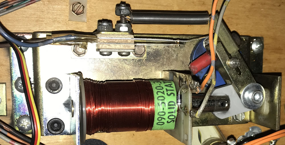
Flipper coils used in all but the earliest pins have two windings on a single coil. One is for power and the second is for hold. Even the ‘modern’ Williams Fliptronics kept the dual coil design. But Data East was able to develop a system that required only one coil for both power and hold, by changing the applied voltage. There are not separate power and hold windings on the coil. As such, there are only two wires going to the coil.

Data East used the pinball machine’s circuitry to control the timing of the high power to the coil. After a short period of time (generally 40 milliseconds), the computer cut the 50 VDC back to 9 VDC to hold the flipper up. Like Fliptronics, the ultimate advantage of this system is that lower power only goes through the flipper and EOS switches, greatly extending their lifetime. Additionally, the EOS switch could stop working and the flippers would continue to operate normally – at least in theory. Data East made a mistake in their first few games (Jurassic Park, Last Action Hero and Tales From The Crypt) and those flippers will not operate properly if the EOS switches are broken or out of adjustment. Later Data East machines did not have this problem and the flippers could continue to operate with defective EOS switches. How to modify early Data East solid state flipper boards.
Unlike Fliptronics, the EOS switch in DE/Sega/Stern flippers are normally closed, just like regular flipper systems. This EOS switch serves a similar function in that it tells the flipper board if something is forcing the flipper back closed. If the flipper is pushed down (by trapping two or more pinballs, for example), then the EOS switch closes and the flipper board sends another 40 millisecond power pulse to open it back up. For this function to work properly, the EOS switch must be in working order and properly adjusted so that it closes when the flipper is moved back ~1/16″ of an inch.

Data East continued to improve on the circuit and this process was continued after DE was acquired by Sega in the mid-1990’s. Click on the image above, or this link, for detailed theory of operation in the Data East / Sega solid state flipper.
Note that the first two Sega Whitestar games, Apollo and Goldeneye, also use this flipper system and not the later Whitestar system referenced below.
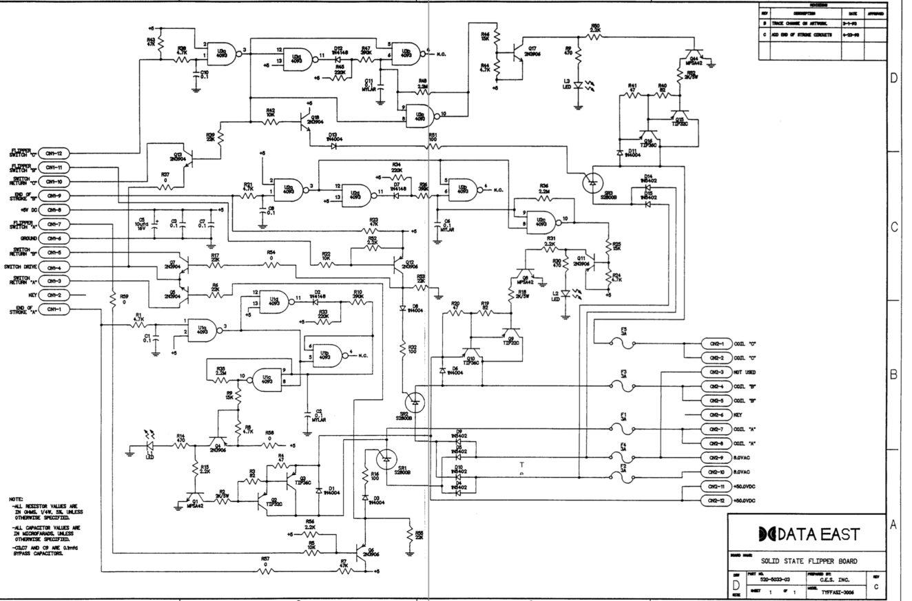
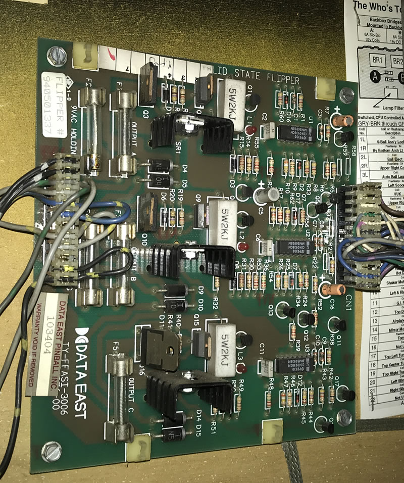
The DE/Sega Flipper Circuit

Unlike Williams, Data East / Sega had at least 5 different flipper boards from MPU Version 3 and 3b. On all (? – be sure to check the schematic for your game!), the 50 VDC for the flippers is generated on a separate power board (PPB-1) which is a different board from the power supply board. If there is not any power for the flippers, check the fuses on this board as well as the bridge rectifier BR-1.

The 50 VDC for the power stroke is then connected to the flipper board at CN2, pins 8 and 9. The hold power is supplied via 8 VAC (!) applied to CN2 at pins 6 and 7. The flipper board converts this to DC through a two diodes for each flipper.
Unlike all other games, the 50 VDC is applied to the coil only when the flipper is energized. The coil is grounded via a flipper enable relay located on the CPU board. To test for presence of 50 VDC, it will be necessary to check it on the flipper board at CN2 pins 8 or 9, not the coil.
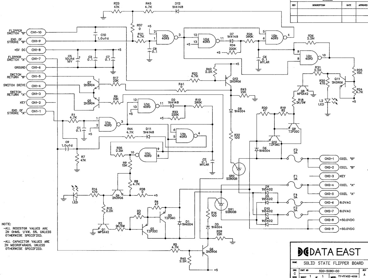
The circuitry for the DE/Sega flipper circuit is far more complex than the Williams Fliptronics board. The circuit, as described in the DE/Sega Flipper Theory photo consists of IC U1 and U2 which are the timing circuit for the power stroke. Q3/Q10 TIP36C ultimately turns on and off the 50 VDC to the coil.

The hold power comes from the 8 VDC which is rectified from the 8 VAC supplied to this board via D4, D5, D9, D10. If the flipper is not held up, check the AC and DC voltages. Q6/Q12 and SR1/SR2 apply the 8 VDC to the coil.
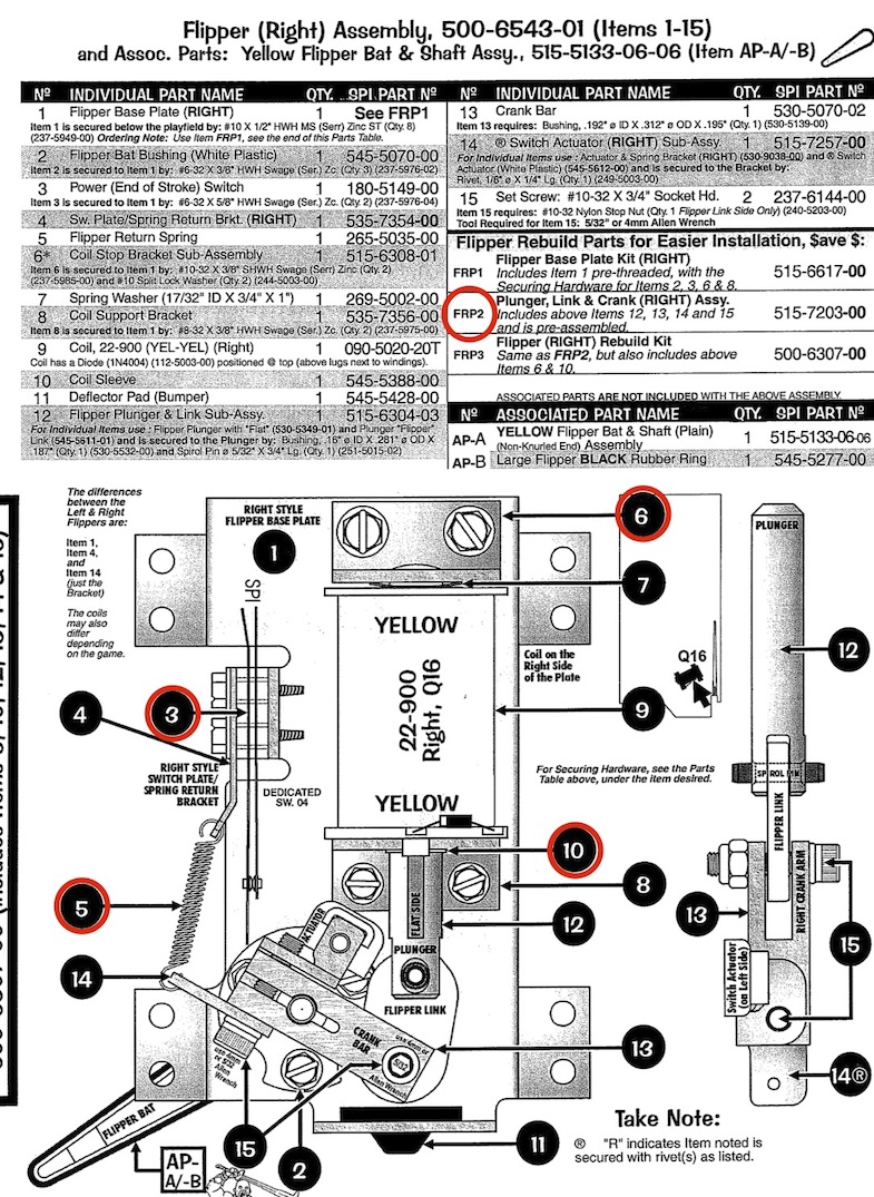
Three Flipper Circuits
The circuit board for three flipper games contains the same circuit design as those used in two flipper games and works the same way. The third flipper is usually designated as Coil ‘C’. The only difference is that Col ‘C’ does not have an EOS switch. Considering the only role the EOS switch plays with a flipper is to add power when trapping the ball(s), this does not seem to be an issue with the way upper flippers are designed to be used.
Troubleshooting DE/Sega Flippers
If the flippers do not work at all, check the operation of the relay on the CPU board. This relay grounds the coils (the opposite of what happens on Bally / Williams pins where the relay applies the voltage to the coils).
For the power circuit, the following components need to be tested:
| Coil | TIP36C | TIP32C | MPSA42 | 2N3906 |
| A | Q3 | Q2 | Q1 | Q4 |
| B | Q10 | Q9 | Q8 | Q11 |
| C | Q16 | Q15 | Q44 | Q17 |
Check that there is 50 VDC coming into the flipper board at CN2. Check there is 8 VAC at CN2 (measure AC across these two wires). The positions on the plug depend on whether using the 2 or 3 flipper board.
Also check the fuses and their fuse holder clips as these are known to fail. Check for ~8 VDC at the band side of diodes D9/D10 and D4/D5. On early games, defective EOS switches can cause issues, but always clean and adjust the EOS switches anyway. Note that there is not an EOS switch on DE/Sega upper flippers.
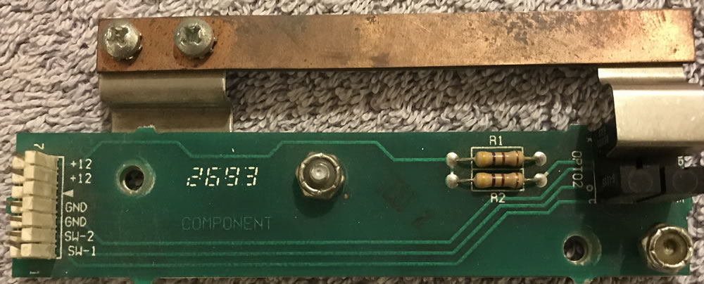
The LEDs on the boards confirm that the flipper buttons are being pressed and also should confirm that circuit up to the 2N3906 transistor is working.
Usually, when the power circuit fails, it is the TIP36C (Q3, Q10 or Q16). Test the TIP36 transistors using the normal transistor / diode test. Values of 0.5 to 0.7 are good. If that tests good, check the TIP32C. It is less likely that the MPSA42 is defective. If the 2N3906 is not working, then the LED indicator on the board should not be working.
Always check and compare the flipper coil resistances. We like to unplug CN2 when performing this test to insure the circuit board does not affect the reading.
Troubleshooting the Hold Circuit
There are two or three hold circuits depending on the generation of DE/Sega board:
Coil A – Q6 & SR1
Coil B – Q12 & SR2
Coil C – Q18 & SR3
If the power works, but the hold does not, it is the 8 VDC portion of the circuit. It could be SR1 (or SR2, SR3 for the other flippers). It could also be the pre-driver Q6 (or Q12, Q18). In the low power portion of the board, it is possible to use a digital probe to compare the working side vs. the non-working side of the circuit. It may also be possible to use a voltmeter set to DC to measure the changes in the +5 V DC.
In the Coil A circuit, the flipper button activates Q6. Q6 then activates SR1 the low voltage which stays on as long as the flipper button is pushed. If either Q6 or SR1 does not work, the hold function of the flipper will not work.

To test this portion of the circuit, pull out your Digital Probe and connect it to ground and +5 V DC power. Test the base of Q6. It should switch from high to low when the flipper button is pushed. If no, then there is a connection issue to the flipper button, a broken trace / solder joint, or R5 or R40 are bad (highly unlikely).
Next, connect your Digital Probe to the lead of Q6 that is connected to R39 and D3. Press the flipper button again. If the digital probe reading does not change, then Q6 2N3906 is defective.
If the output of Q6 changes with the flipper button, check for continuity to the input of SR1 which is via D3 and R16. If they are good, then SR1 is defective. But these SCRs are generally more reliable than Q6 2N3906.
2N3906 is a PNP transistor TO-92 package. It is available from typical electronics supply houses as well as Marco. SR1 is a S2800B SCR which is available from Marco. The late great GPE lists an alternative as MCR12MG, which is available from the usual electronics supply houses.

Note: Coil B is almost identical to the circuit for Coil A. Coil C is a little different as the signal for the hold circuit comes in through U3a. However, if the power portion of this flipper circuit is working then U3a must be working. After that, the hold circuit for Coil C works the same way as Coil A.
Sega / Stern Solid State Flippers

In the mid-1990’s, Sega introduced a new CPU board system called Whitestar. When Stern purchased Sega, they continued production with the Whitestar system for several more games. The first two, Apollo 13 and Goldeneye used a separate flipper board located in the cabinet like the DE/Sega games did. From Twister on, the flippers were controlled by the power driver board FETs and the CPU.
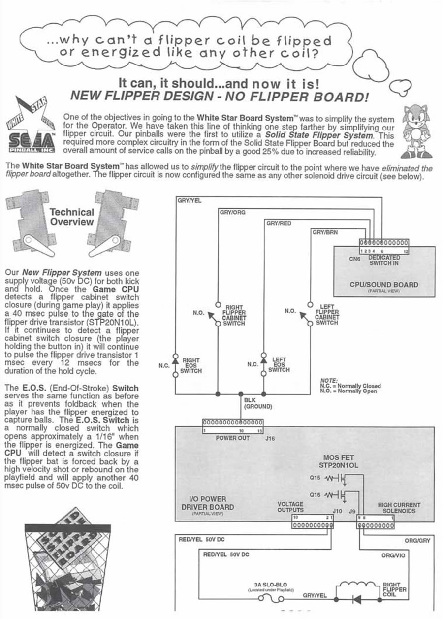
While the DE / Sega system had a 50 VDC and a 8 VDC power supply, the Whitestar system makes use of only one power supply, 50 VDC. The power stroke is a 40 msec pulse like it was on the DE/Sega board; but the hold circuit is now also 50 VDC, but just for 1 msec every 12 msec. This short burst of full power mimics the hold of an 8 VDC power supply because it is a very short duration. The 50 VDC is generated in the power driver board and is also used for the other coils, but the flippers have their own fuses. One fuse is on the power driver board and goes to both flipper coils. The other two fuses are located near the flippers. Note that there may be some variation of this setup from game to game.
Note: Apollo and Goldeneye, early Whitestar games, still have the Solid State Flipper Board and run on the De/Sega system of 50V power and 9V hold. See the previous section for how those work.

The EOS switch plays the same role as before: it detects if the flipper is being pushed too much and tells the computer to increase the power. The flipper can operate with a defective EOS switch.
According to Sega / Stern: The EOS switch should be adjusted so that it opens 1/16″ when the flipper is open. During this period of time, the computer applies the short pulse of 1 msec ever 12 msec. If the flipper is pushed down, so that the EOS switch closes, the computer then applies 50VDC for 40 msec. If the EOS switch is missing or misadjusted, then the flipper could be forced closed while trapping pinball(s) with the flipper.
The flipper switches are dedicated switches to the CPU coming in on CN6. Closing the flipper switch grounds the connection to the CPU.
Stern Flipper Software Upgrade
Note that later Whitestar games, such as Lord of the Rings, had a software update allowing the operator to change the strength of the flippers by modifying the timing of the power stroke. These are Standard Adjustments 53, 54, 55. Stern partially explained the purpose of these adjustments, so we did our best to interpret them.
“Flippers will now fire when the button is pushed until the End-of-Stroke (EOS) Switch closure is seen. When EOS is seen, continue firing for the amount of time in Std. Adj. 55. When this time is expired, if the minimum time has not yet been met (Std. Adj. 53), then keep firing until it has. Otherwise switch to hold power. • If the flipper has been firing and it reaches the maximum (Std. Adj. 54), then switch to hold power. • If the flipper caves-in (EOS re-closes) while the button is still held, then refire the flipper at full power. Switch to hold power as soon as EOS is seen, no minimum times are enforced in this situation. • If the flipper caves in several times on the same single flipper button press, then stop refiring at full power and just stay at hold. • If the flipper fails to open the EOS switch several times, then assume it isn’t working and fall back to a “safe” fire time so as not to burn up the coil. Three (3) new STANDARD ADJUSTMENTS were added to control the flippers.“
To us, it seems as if the EOS switch now plays a much greater role than it used to, which it just detected the flipper being forced closed.
 “53 FLIPPER ADJ 1: Set between 05 to 40. Default is 10.
This adjustment sets the minimum fire time for a flipper coil in milliseconds.“
“When this time [Adj 55] is expired, if the minimum time has not yet been met (Std. Adj. 53), then keep firing until it has.” This appears to us to set a minimum time to fire the coil at full power, when the switch closure occurs. Oddly, if Adj 55 is set to zero or any value less than Adj 53, wouldn’t Adj 53 always control?
“54 FLIPPER ADJ 2: Set between 40 to 60. Default is 50.
This adjustment sets the maximum fire time for a flipper coil in milliseconds.“
This allows the operator to adjust how long the power stroke is applied, no matter when the EOS switch opens. Interestingly, the default is 50 msec when it used to be 40. This is especially beneficial if the EOS switch breaks.
“55 FLIPPER ADJ 3: Set between 0 to 10. Default is 3.
This adjustment sets the amount of time to fire the coil after the EOS switch is seen in milliseconds.“
“Flippers will now fire when the button is pushed until the End-of-Stroke (EOS) Switch closure is seen” is confusing. If this were to mean closing, then this seems to us to apply if the flipper is forced closed due to a force such as trapping a pinball. The amount used to be 3 msec, which is the default here.
The Sega/ Stern Whitestar Flipper Circuit

This is the simplest circuitry of them all – it works like any of the other coils on the game. The 8A TIP102 (or TIP120) are no longer used. Instead, a more robust 100V 20A MOSFET STP 20N10L is in its place. IRL540 is a direct substitute.
To fire the flipper, data is sent over from the CPU which tells IC U2 to turn on. The signal comes out to the FET transistor controlling the flipper. The FET turns on, completing the circuit to ground.

Note that there is not a snubber diode on the I/O board. If the diode on the coil is broken or open, the FET is likely to blow. The transistor used to activate the flipper coil may vary from machine to machine, so it is important to look at the coil chart table to identify which transistor is used.
Troubleshooting Sega/Stern Whitestar Flippers

If both flippers do not work, check the fuse located on the power driver board. Check your manual for the correct value of the fuse.
If one flipper does not work, check the fuse to that flipper. The fuse should be located underneath the playfield in the vicinity of the flipper.
Check for voltage present. Note that this may test higher than 50 VDC when it is not under load.
If the flipper still does not operate, it is possible to check the circuit the same way that coils are tested in older WPC pins: briefly short the tab of the FET to ground. The flipper should activate. If it does, it is likely that the FET (MOSFET) has failed. Replace it with an IRL540. Important: do not use a TIP 120/102 transistor.
If the flipper activates (locks on) when the game is started, then the FET is likely shorted. Replace it with an IRL540.
If the FET has failed, be sure to inspect the diode on the coil. If the diode is broken, missing or open, then the FET will blow again.
Comments
Comments, including suggestions, improvements, errors, etc. are welcome (see below).
If you have a specific question about your game that does not directly apply to solid state flippers, please see our FAQ section.
External Links
DE/Sega/Stern History
Optos and Weak Flippers
Copyright 2006 – 2025, all rights reserved.
Hi,
If I am building my own pinball machine from scratch, do you see any drawback to having the EOS switch go back to simple gates which directly switch off the Power Coil and switch on the Hold coil, given my using the Williams driver approach/schematic? I could directly use the Button logic level output to make it all happen, keeping my microcontroller out of it (although letting it disable the path when not in play mode).
Thanks,
Kerry
Congratulations on building a pinball machine from scratch! What a cool undertaking.
We believe that the main reason that pinball manufacturers introduced computer controlled flippers was to increase their reliability. With non-computer controlled, the EOS switch wears and the flipper loses power. And a EOS switch that does not open means a burned coil.
Computer control removes the wear from the switches and potentially allows computer adjustments, something that Stern added with Lord of the Rings. With computer controlled flippers, it is usually the linkage and coil stop that wear first. Plus the EOS switch can break and the flipper will still work.
With home use pinball, wear and tear is less of an issue. So using non-computer controlled flippers (which is what we think you are asking) should not be a significant disadvantage.
We would suggest using the pre-Fliptronics WPC design. The parts are readily available, the exterior spring is more reliable, and the parallel coil combined with the capacitor on the EOS switch means a long life. We also suggest that you use a 50 V DC power supply for the flippers.
If you buy the assembly from Pinball Life, be sure to add the capacitor to the switch.
Best of luck. Please share photos of your progress.
Good morning,
I believe I have found the root cause for the “weak flipper” controversy.
See this post on Pinside with scope shoots measurements taken at the coil, with a strong 12V and a not so strong 12V, you can see that the effect is a reduced pulse (50ms instead of 100ms), followed by a train of oscillations which correlates with the comparator output on the power board output.
https://pinside.com/pinball/forum/topic/weak-flipper-low-12v-wpc-dcs-need-expert-advice#post-6635342
(i’m the author of this post)
The optos are not led, they are photo transistor. So the amount of light emitted by the emitter and received by the receiving phototransistor, is dependent on the supply voltage and whether the optical path is clean.
It the receiver does not receive enough light, when lit it will operate in transient instead of in commuting mode. It will therefore output a voltage level which can vary linerarly, as opposed to a binary value which is then used as an input to the comparator. If the voltage at the input of the comparator is right at the threshold, the comparator output will oscillate, thus generating oscillations on the coil command.
Ergo… weak flippers.
Let me know your thoughts.
As for me I could squarely reproduce the issue back and forth: weak 12V (11.8V more precisely), weak flipper, attached scope shoot with shorter pulse, strong 12V (12.3V), strong flipper, attached scope shoot with 100ms inverted pulse.
WOW! Thanks.
At one point, the obsessive one of the group (who shall not be named) tried a study where they put a variable pot on the receiver and adjusted it. All they could find was a sharp drop off in operation from 100% to 0% at a certain resistance. There was a narrow point where the flipper would vibrate (flitter). At no point did they see weak flippers or hot coils. The variable resistor was on the Fliptronics side of the opto.
None of this explained observations of ‘weak’ flippers nor ‘hot’ coils.
Just to clarify your comment, ‘The optos are not led, they are photo transistor.’ It is our understanding that these optos are a transmitter, which is a UV LED, and a phototransistor receiver. The ‘horseshoe’ shaped optos used by Williams are no longer available. But there is an aftermarket one that might substitute. Here is the data sheet:
https://pdf1.alldatasheet.com/datasheet-pdf/view/139963/OPTEK/OPB804.html
“OPB804 contains an IRLED and phototransistor paired in an opaque plastic housing .”
So, if we understand the discussion accurately, the problem is the 12V going to the phototransistor (opto receiver) and not the LED (transmitter)? In the tests done here, we put the variable resistor on the phototransistor, we are surprised that they could not reproduce what you are seeing.
In the Fliptronics board and Flipper Opto board there is a LM339 comparator with a 1K resistor on the input acting to keep the input high (pull up). When the flipper opto conducts, it pulls this voltage down and flips the LM339 comparator.
https://www.onsemi.com/pdf/datasheet/lm339-d.pdf
“therefore output a voltage level which can vary linerarly”
On page 6 of the data sheet, the response of the LM339 is shown when presented with a sine wave. The output is a square wave, which shows as the voltage on the input to the LM339 drops, it should abruptly switch, not vary. Of course, that does not mean, at the center point, the output might not be a series of pulses. That is what the test group here saw – the flipper would flutter.
Looking at page 3-15 of the Scared Stiff manual, there is a schematic for the flipper board. [Note that there is a first and second generation of this board and there is some theory that the second generation ‘solved’ this weak flipper issue, but we don’t have confirmation of that.] In this schematic, there is a 470 ohm resistor to drop the voltage for the UV LED (transmitter) down to its operating range. The photodiode (receiver) gets its 12V from the Fliptronics board. The 1K resistor on the Fliptronics board is in series with the photodiode.
That could mean that either the 1K resistor could be reduced to offset the effect of the lower 12 supply. But it would have to be the proper amount so that the photodiode is not overloaded when the 12V is running a bit over 13 V DC. The V(BR) is 30 V DC. But this would also increase the current flow through the photodiode, so that would have to be taken into account. The power dissipation is 100 mW.
But it is still not clear to us if this is a problem with low voltage to the photodiode (receiver) or the UV LED (transmitter).
The plan was to go back and repeat this experiment on the transmitter side, but that has never been done.
My comment on the ” output a voltage level which can vary linerarly” is for the receiving phototransistor, not the comparator.
My assumption are:
– the emitter light intensity is driven by the voltage level
– If the lens are partially obscured on top of that, the resulting emitting light is lower, so the receiving photo transistor current generation on it’s “base” (which is what the photo sensitive cell generates) is also low
This is where there could be two interpretations IMO, here’s two scenarios I think could happen:
– Current generated by the light sensitive cell is too low: the transistor is in linear mode, it generates a current flow through collector/base which is insufficient to actually pull to ground the output, so the comparator sees on it’s input a voltage level which would be around it’s trigger point (so 5V), resulting into “pulses” on it’s output
– Or, the light threshold vs the emitted light received by the photo transistor are very close, thus generating pulses on the output of the photo transistors (which are then converted to pulses by the comparator)
Either way, result is the same: comparator issues pulses instead of a solid stable signal.
To validate this, we would need to:
– add “dirt” to the lens, to mimic the effect of dirty optos
– Slowly reduce voltage
– Take scope measurements of the output of the photo transistor, and the output of the comparator
To note: on Indiana Jones the upper mini playfield is controlled by flipper buttons. Before cleaning my optos, control of the playfield was really erratic, pressing the button continuously resulted into an intermittend rotation. As if the control was a series of pulse instead of a solid signal (sounds familiar…).
Apologies for my english, not sure what I wrote makes a lot of sense, it’s been a while since I exchanged on a tech subject like this, so my vocabulary is lacking.
‘My comment on the ” output a voltage level which can vary linerarly” is for the receiving phototransistor, not the comparator.’
My mistake. Sorry.
“– Current generated by the light sensitive cell is too low: the transistor is in linear mode, it generates a current flow through collector/base which is insufficient to actually pull to ground the output, so the comparator sees on it’s input a voltage level which would be around it’s trigger point (so 5V), resulting into “pulses” on it’s output”
A great theory. Our person here, through testing, did confirm that at a certain voltage, the flipper would pulse, so that means that the comparator must be (?) pulsing. But he also found that point is a very precise (narrow) point. It seemed unlikely (but possible) to us that all of these ‘dirty’ optos causing weak flippers were exactly hitting that point.
“…comparator issues pulses instead of a solid stable signal.” Your oscilloscope readings certain seems to validate that.
We were hoping that someday we would come across optical filters with different levels of ‘light transmission’ (for lack of a better technical term). One person here used to work with spectrophotometers and used to use a set to calibrate the equipment. But we don’t have access to these filters.
We had an Indiana Jones that had issues also with the upper playfield controls. We ended up putting in a new aftermarket opto board for the motor and that solved it. I think in our case, it was likely that the 30 year old transmitters had low output. We see that a lot with separate opto boards and, when we are lazy, put in a new raw LED transmitter and skip replacing the receiver photodiode. 90+% of the time, that fixes the problem. But it is better to replace both not only because the receiver is old, but to insure that the wavelengths are matched.
We still want to play around with variable resistors (pots or potentiometers) on both the receiver and transmitter to see if we can reproduce the issue.
There is also the variable that there might be differences in lots of comparators and some may exhibit this problem and others not.
Your English and writing is excellent. I wish all were as skilled as you are.
Thank you for doing this research and thoughtful analysis.
Did Goldeneye have a conversation in firmware to support the new whitestar configuration not requiring the SSFB?
It appears that is what the operator did to my machine however the game was working and now flippers stay on even without input onto the CPU board. When beginning a game it is asking to flip the flippers to select game type however even without the fuses the switches don’t seem to work.
I confirmed with a DMM that the wiring is still good so ideas?
A great question and we do not know the answer. To the best of our knowledge, the first two Whitestar games, Apollo and Goldeneye still used the SSFB (solid state flipper board).
But in looking at some of the website that supply EPROMs, they group Apollo and Goldeneye in with the other Whitestar games. We have tried searching for information on this topic and have not found anything.
If you find additional information, please let us know.
Thank you.