Most solid state pinball machines can be set to free play by going into the service menu settings. But a few are a challenge.
Warning: Do not fix this problem by drilling a hole someplace for an additional switch. Not only is this unnecessary, it can reduce the value of your pinball machine to collectors. And it is just plain stupid.
Note: Click on the image for a larger picture.
EM Games – Set To Free Play
EM games do not have a free play setting. But converting them to free play is pretty easy and usually just involves soldering a jumper wire or bending a contact.


For EM games, there is a paid game counter (or free game wheel) in the backbox. If the number of games is 1 or above, a switch is closed. If that number is zero, then a switch opens.
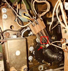
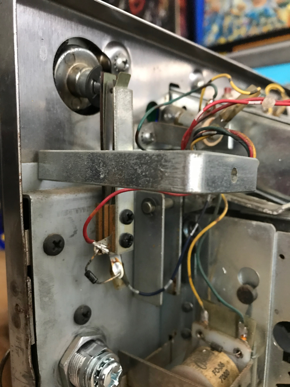
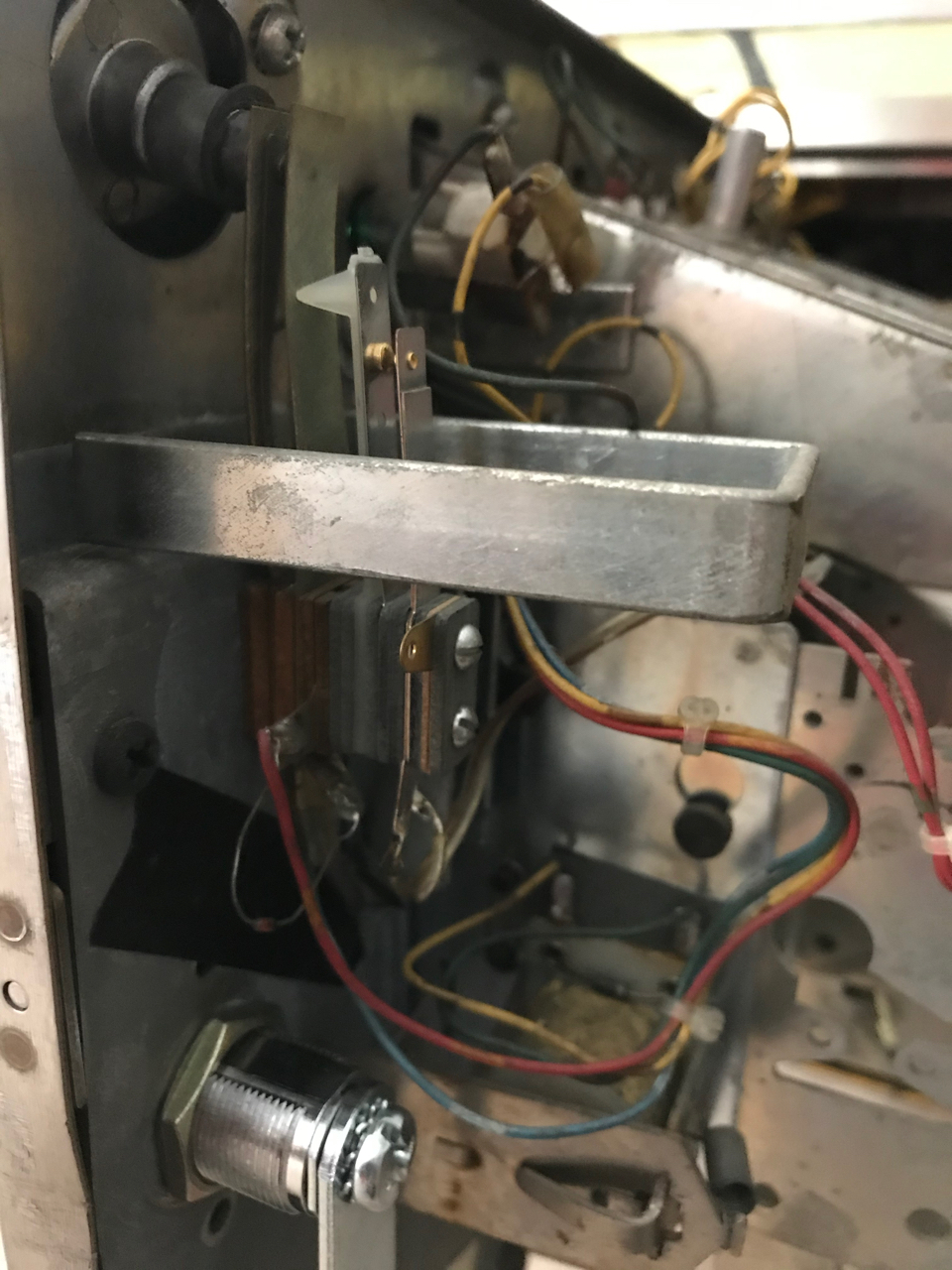
The first image is a Gottlieb Play Ball. In the photo, there are zero games on the free game wheel and the switch is open. Second image shows when one game is on the reel, the switch closes. In this free play setup, a wire jumper was soldered on the switch (see yellow – red wire) so that the switch acts closed with zero games on the wheel.
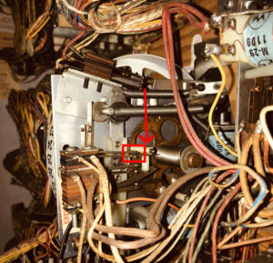
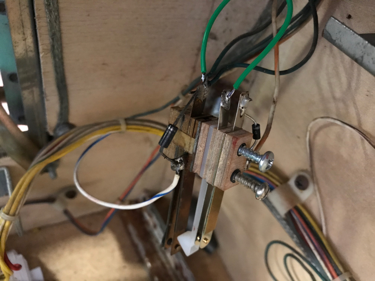
In the third picture, there are zero games on the free play wheel on a Williams Grand Prix. The arm pushes down and the switch should open. But the top contact has been bent down so that the switch makes contact. This allows free play when there are zero games present.
Some people enable free play by clipping the wire to the solenoid that removes games as play is started. This will work for free play, but we do not like this technique since the free play wheel will eventually move up to the highest number of games and stay there. The technique above retains the normal motion of the free play wheel, while still enabling games with zero on the wheel.
Early Bally / Stern and Williams SS
Williams SS 3 – 7, 9, 11
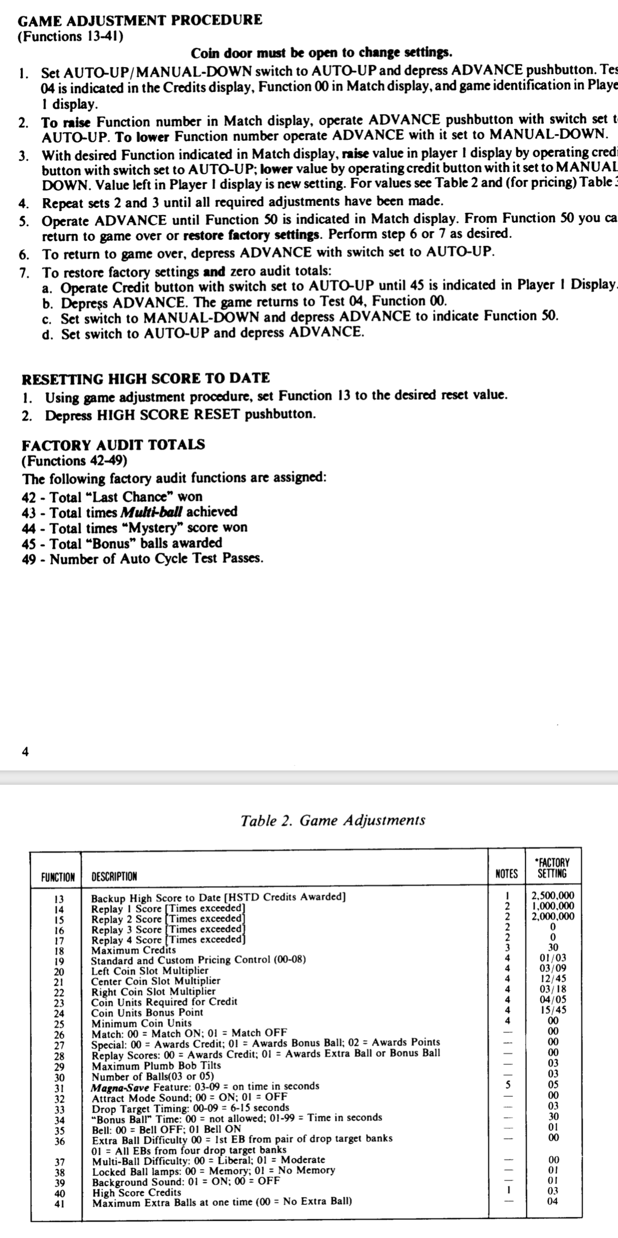
Williams games prior to WPC (~1990 and older) can be set to free play by going into the service menu and setting the maximum number of games to zero. In a game like Black Knight, that means going to game adjustments and setting #18 to zero.
However the first Williams System 3 or System 4 does not have this option. Although maximum number of games may be set to zero, it does not enable free play. Try setting your Williams pin to zero. If free play works, you are done. If not, you will need a switch as shown in the information below.
Converting Bally / Stern and Williams 3, 4 SS to Free Play
None of the early Bally and Stern games have a free play setting. These are the pins identified as Bally MPU AS-2518-17, AS-2518-35, AS-2518-133, Stern M-100, and M-200 MPU.
| If using an aftermarket MPU such as Alltek, there is a DIP switch setting for Bally games. But this does not work for Stern games and the double switch (below) must be used. Weebly seems to have a free play setting for both Bally and Stern. |
The concept is simple: convert the start switch to two switches. The first one adds a game and the second one starts a game. The game is added by moving the wire from the coin mechanism to the switch. Application of this concept is only mildly tricky.
Supplies Needed
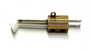
1) A second switch. This can be any old leaf switch left around, but it must have an insulator (usually paper) to isolate this switch from the existing switch. A Williams lane change switch sw-1a-150 will work just fine.

2) Two screws. The two switches are thicker than the original one. Usually 1″ to 1 & 1/2″ screws are needed.
*Most Williams start switches of this era are mounted on the wood on the left, so a wood screw is needed. The wood screw must be small enough to fit through the switch holes and the sleeve within those holes. We have used #2 round head wood screws, but the length varies with the setup. The length of the screw must be checked to insure it does not come all the way through the cabinet!
*Bally / Stern pins have the start switch located on the coin door. Machine screws #4-40 of 1″ to 1 & 1/4″ should work. Length depends on the type of second switch used.
3) Light gauge wire typically #20 or #22 stranded wire.
4) A diode, 1N4004 (or 1N4007).

5) Loctite Blue 242 (optional). This will prevent the machine screws from coming loose on Bally / Stern coin doors. Williams uses wood screws, and this is not needed.
6) Switch adjustment tool – which you have anyway.
Note: When wiring, the current start wiring is moved to the new switch, on the back of the existing one. This is so a game is added first, and then the game is started. If the existing wiring is left on the start switch, a person may not press hard enough to add a game. Or may have to press twice. Avoid this and move the wiring.
Early Bally / Stern SS Free Play
None of the early Bally and Stern pins have a free play setting on the original MPU. Some people get around this by setting a low award score and the award to free play. But that takes away from options to use this setting for game rewards.
The EPROM for this game could be upgraded to have a free play setting. But replacement EPROMs usually require changing the jumpers on the MPU board, a somewhat complex and annoying process.

The easy solution is to install that second switch:
1) Remove the current start switch from the coin door mechanism. Take a photo of how the wires are connected for reference.
2) Remove the wires, but leave the diode in place. Install the wires and a new diode on the new switch (#1 in ‘Supplies Needed’). Install a diode in the same position as on the original switch, with the banded side towards the same wire. Your wiring should look exactly the same as they did on the original switch.

3) Hold the original switch in front and put the new switch on top in back. Obtain two machines screws that will be long enough to go through both switches and into the threads in the coin door that held the start switch. Apply some Loctite Blue 242 to the start of the threads. Assemble into position and tighten the screws.
4) At the bottom of the coin mechanisms is a switch with two wires attached. Remove those two wires from the switch. Attach them to the original switch which is closest to the coin door. Most of these coin switches have a diode. Be sure to wire this to the original switch with the same wire going to the banded side of the diode as on the coin switch.
5) Using your switch adjusting tool, adjust the inner switch so that when the start button is pressed in, the contacts meet. They should touch after pushing in the switch a little bit, perhaps 1/8″, but not with just a light touch.
6) Adjust the new, second switch so that the switch closes when the start button is pushed most of the way in.
Steps 5) and 6) are technique dependent. You may have to play with it a bit. If 5), the contacts are too tight, the game could restart during game play. If the switches are not tight enough, the game may not start.
7) Use your manual so that just one game is added when hitting the start button. This process varies from game to game, but usually involves changing the small switches on the MPU board. It will still work if more than one game is added, but one game added per one game started is a more elegant solution.
Early Williams SS Free Play

Early Williams System 3 or System 4 cannot be set to free play and the best option is putting a second switch on top of the original switch, as with the Bally / Stern above. This is a little trickier as the start switch is mounted on the wood cabinet.
With Williams, the start wiring is on the cabinet, while the coin wiring goes to the coin door. Either the wiring from the coin door will need to be removed from the coin door, or the wiring will have to be identified and cut, then attached to the original switch. This is not difficult, but takes a bit more effort.

Click on the Williams Wiring photo. Note that the ‘Credit Button’, which starts the game, shares the same wire as the coin switches. In Disco Fever, this is the Green – Brown wire, which is column 1. That wire can be jumpered from the
Note: It is crucial to select wood screws that are narrow enough to go through the switches and leave those sleeves in place, get firmly into the wooden cabinet, but NOT come through the front.
1) Take a photo of the current wiring of the start switch. The wiring will be moved to the new switch, mounted behind the current start switch and it is important to wire it properly.
2) Look at the color wires. There will be one wire on the start switch that is the same color as the wire on the coin switches. In most games, that will be a Green – Brown wire. Leave that in place. Remove the other wire, but leave the diode in place.
3) Place the new switch behind the existing switch. If needed, hold them together temporarily with a rubber band.
Note that these switches have three contacts. Two of the contacts go to the ‘leaf’ switches. One does not.
 4) Run a short length of wire from the Green – Brown wire on the original switch to tab c) on the new switch. Connect a diode from b) to a). Note that the banded side needs to be on b).
5) Pick one of the wires from the coin switches. It does not matter which one. In the Disco Fever schematic, the wire would be White – Yellow, White – Green or White Blue.
The other wire, White – Violet goes to the slam switch and must not be used.
6) The easiest is to find that color wire in the bundle prior to going to the coin door and cut it. Try to cut it close enough to the coin door or on the coin door so that this wire can be connected to the switch. Then connect coin door wire to tab a) on the original start switch to the the non-banded side of the diode.
7) Take the unsoldered wire from the original start switch and solder it to tab a) on the new switch. Tab a) will also have the non-banded side of the diode attached.
8) Attach the two switches back in place to the cabinet using the new wood screws. Insure that the screws are long enough to hold the switches firmly in place, but not too long so that they do not come through the front of the cabinet.
9) Using your switch adjusting tool, adjust the inner switch so that when the start button is pressed in, the contacts meet. They should touch after pushing in the switch a little bit, perhaps 1/8″, but not with just a light touch.
10) Adjust the new, second switch so that the switch closes when the start button is pushed most of the way in.
Steps 9) and 10) are technique dependent. You may have to play with it a bit. If 9), the contacts are too tight, the game could restart during game play. If the switches are not tight enough, the game may not start.
11) Use your manual so that just one game is added when hitting the start button. This process varies from game to game, but usually involves changing the small switches on the MPU board. This is under the ‘Game Pricing’ section. It will still work if more than one game is added, but one game added per one game started is a more elegant solution.
Comments
Comments, including suggestions, improvements, errors, etc. are welcome (see below).
If you have a specific question about your game that does not directly apply to setting a game to free play, please see our FAQ section.
Your site is an incredible wealth of detailed information and photos. You could have been a brain surgeon!
The ’64 Gottlieb that I acquired had free play but the credit reel (15 max) was set in a non-numbered area (the little box showed blank) and the reel did not increase or decrease and so the knocker wouldn’t fire. I now have it adjusted so that the reel and knocker work like they should EXCEPT that it works from 1-15 instead of 0-15. It won’t go above 15 which is correct but it won’t go from 1 down to 0 when new game is started. If I manually snap it down to 0 the switch opens and game won’t start as would be typical on a non-adjusted non-free play game.
So I was just going to leave well enough alone but I figured that maybe this is a simple fix and would be obvious to you without seeing pictures. If not, oh well. Being relatively new at this I was excited to get it to this point. I’m fine with taking apart sluggish/frozen steppers, cleaning stuff and making simple adjustments but don’t want to mess up what I accomplished.
I’m going to be using your remarkable website for lots of stuff! Thanks for your hard work.
Jerry
Thank you for the nice comments, Jerry.
It appears to us that, somehow, a previous owner set the credit reel so that it will not go below “1”. Except that when you got it, the reel was in a blank area. You then fixed it.
We looked at a 1970 Gottlieb Play Ball to see if we could figure out what is going on with yours. We cannot see any way that it could intentionally be set that way, to stop at “1” – maybe we missed something.
Guessing, we are thinking that the spring wound on the center of the wheel needs to be tightened as little as possible? Or the wheel is gummed up a bit too much to turn freely to the zero position. Sometimes it maybe better to just leave things working. But if you are adventurous, take the credit wheel apart and clean it up such as shown in the instructions and see if it will then return all the way to zero.
Please see the “Credit Stepper” section.
Thanks again for the nice comments.
-The Home Pinball Repair Team
Thanks for site. It has a wealth of information.
I have Williams Casanova (1966) that I bought about 20 years ago. Worked fine then but after 16 years in storage needs help. I am new to repairing pin machines.
The unit had already been set to free play. Opening it up, I noticed that the ball and pendulum for tilt are missing. I found a replacement bob for sale but what size ball is needed?
Thanks, Tim
Most machines use a smaller metal ball for the tilt mechanism. We cannot be certain that all games use this size, but we have never had a problem with this one.
https://www.marcospecialties.com/pinball-parts/PB1516
It is great that you are installing these, but they are not required for game play. But it will keep people from lifting the machine up and possibly damaging it. Or getting lots of free games.