Caution
B. Introduction
C. Parts Needed
D. Getting Started
E. Installation – the ICs
F. Installation – the Hardware
Pinball machines contain potentially lethal voltage. Dangerous voltage may remain for a period even after it is unplugged. Prior to opening a pinball machine, be certain to unplug it, then turn it on to insure that it was actually unplugged. It is recommended that the machine be allowed to sit several minutes to allow any remaining power to dissipate. Voltages as high as 120 VAC can be present on any plugged in machine and it can be lethal.
Repair should be left to properly trained personnel. If you are not qualified, you should not work on a pinball machine. This article is not intended to be used by untrained personnel.
Proceed at your own risk! The writer assumes no responsibility for accuracy of this procedure nor for damage to your property.
Introduction – Lord of the Rings Pinball (LOTR)
The original Lord of the Rings was manufactured by Stern in 2003 and proved to be one of the most popular and sought after pinball machines in history. It was so popular that Stern resumed manufacturing in 2009 with a “Limited Edition” version that included several upgrades, at a higher price. One of these upgrades was the addition of a shaker motor.
Owners of the original 2003 (non-LE) machines wanted to add as many of the upgrades as possible. A shaker motor is easy to add, but getting it to work with the 2003 machine had several barriers including different incompatible software and hardware. That rarely stops determined hobbyists.
Note: Click on most images for a larger photo.
Parts Needed
The following parts are required:
1) Shaker – Cointaker, Pinbits, Marco, Pinball Life. Note: Check with the reseller to insure that this model of shaker will work with a Stern Whitestar pinball machine prior to purchasing or installation.
2) LE PAL chip – integrated circuit for software update – Pinbits, Matts Basement Arcade.
3) CPU 10.02 (U210) –Matts Basement Arcade – be certain to choose 10.02 from the dropdown menu. That Pinball Place. – now appears to be offline.
4) Display 10.00 (ROM 0) – Matts Basement Arcade – be certain to choose 10.00 display ROM from the dropdown menu – see instructions below. That Pinball Place. – now appears to be offline. Note that some machines may already have display ROM 0 of 10.00 and it might not be necessary to order this.
5) OS 8 Bootflash – Matts Basement Arcade – be certain to choose OS8 Bootflash from the dropdown menu. Also download the Service Bulletin from Stern Pinball. See instructions below.
Optional (or as needed):
6) IDC Pusher for WPC Backbox 0.156″ Connectors – Pinball Life, Marco
7) MOSFET STP20N10L (IRL540 is a direct substitute) – Marco, GPE (IRL540), Pinball Life – see note below.
8) IC Removal Tool – better than a screwdriver. Marco. Most people just use a small screwdriver, but the IC legs get bent. This is better.
Getting Started

In order to do the conversions, your Lord of the Rings will need the following: CPU EPROM 10.02, Display EPROM 10.00, LE PAL chip, OS 8 and a driver transistor at Q12.
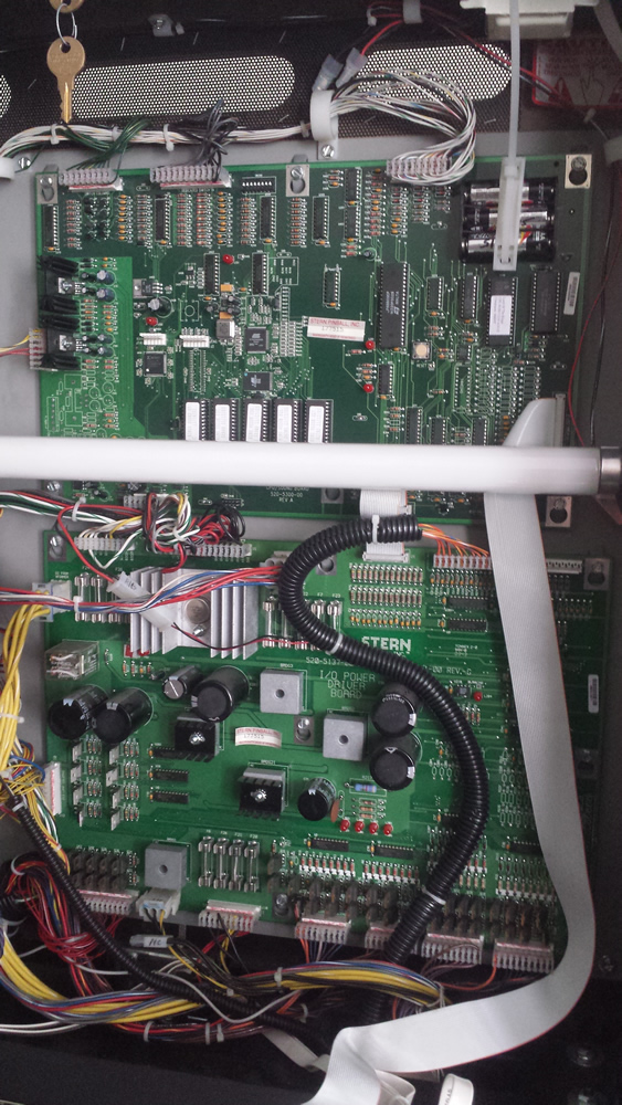
First, find out what IC’s are currently in the machine and what OS it is running. Open up the backbox and find the CPU EPROM and the Display EPROM (top board in above photo). Each will have a label on them specifying what version is running.
The latest that the early (2003) can run without modifications is EPROM 10.00. But 10.02 is needed to run the shaker motor. In order to upgrade from 10.00 to 10.02, the display chip must also be 10.00. If your display EPROM is not 10.00, then order both CPU 10.02 and display 10.00 (see parts list). It is not necessary to replace the sound EPROMS.
Next, determine what OS your pinball machine is running. Locate LED1 on the same board as the EPROM’s. Turn on the pinball machine. There will be an initial flash, a pause, followed by a series of flashes. Count the series of flashes (not including the initial one). The number of flashes is your OS version. Most Lord of the Rings pinball machines will flash four times. We want to upgrade to OS 8. If your machine does not flash 8 times, you will need the ‘OS 8 Bootflash’ from the parts list (item #8, above).
Do You Have the MOSFET Driver ?
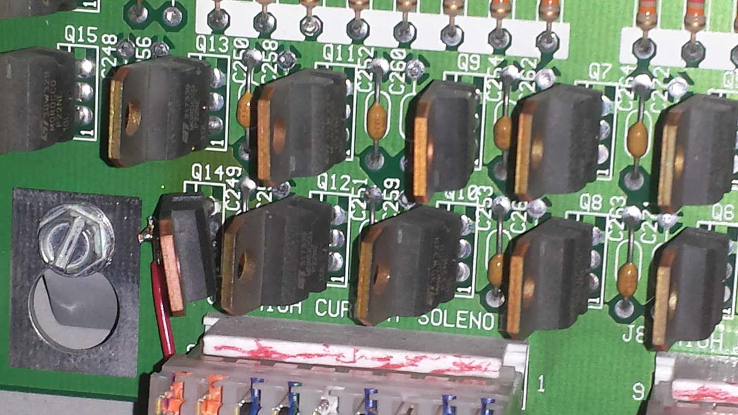
Take a look at the MOSFET** towards the bottom of the I/O circuit board (bottom board). Just above connector J9 are a series of transistors. Locate transistor Q12. If there is one there, you do not need to order the transistor item 7). If there is an empty spot, you must order transistor STP20N10L. When ordering, contact the vendor to insure that the transistor ordered is the correct one. The ones we have listed were recommended to us, but we have not tested them and cannot vouch that they are replacements. [Editor’s note: IRL540 is a direct substitute.]
** MOSFETs look like transistors used in Bally and Williams driver boards. But MOSFETs are not transistors.
Installation – The ICs

The first step is upgrading the EPROM’s and OS. When certain that this is working, the hardware will be installed. Note that replacing these ICs will remove all settings in the pinball machine setup, so it maybe wise to record games settings, high scores, etc.
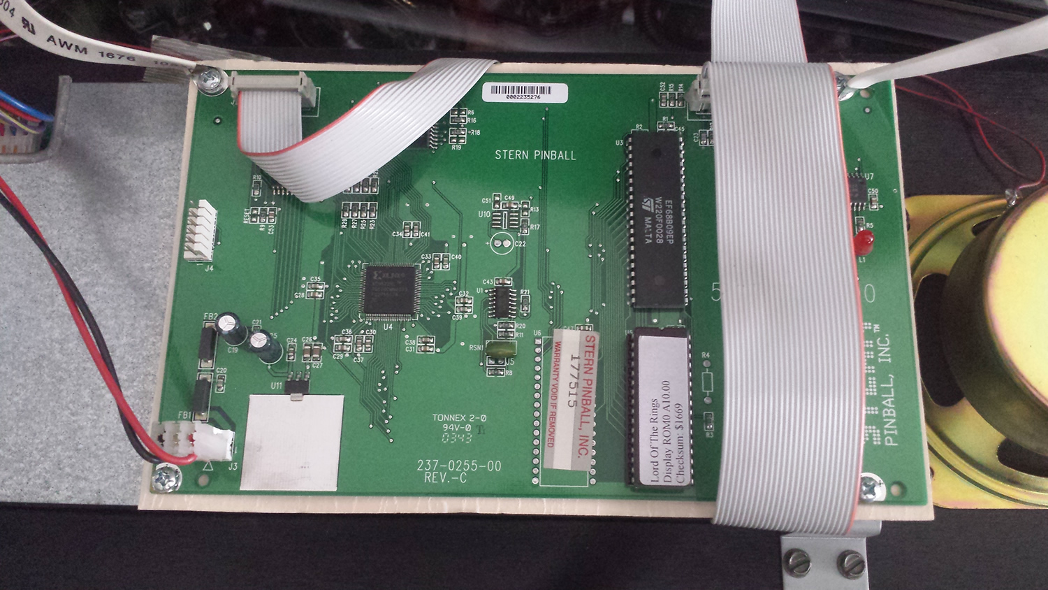
1) Turn off the pinball machine. Note that the IC has a dot on one end. In all Lord of the Rings pinball machines we have seen, this dot is pointing down. Remove the CPU EPROM (see Photo (2) above for location of the CPU EPROM – click on the image for a larger photo). If you have never done this before, an IC removal tool is great. But prying under one end, slowly and carefully, then the other can do the trick. Do not bend the legs.
2) Note the dot on the end of the replacement 10.02 EPROM. Place it in the same direction as the original. CAUTION: Inserting this backwards will destroy the EPROM. Be careful that all the legs are in the socket prior to pushing in. If they are outside, or worse, underneath, the legs will bend and might not be able to be straightened without breaking them off.
We find that many times the legs stick out too far to line up with the holder, so we gently push in the legs with a finger so that they line up. Once the legs are in place, firmly press the IC into the socket. This can take a fair amount of force.
3) Next, install the LE PAL IC. This is a much smaller IC, located immediately to the left of the CPU EPROM IC. This chip is visible in the Photo (2). Remove the original one and install the replacement just like in step 2). Again, be certain that the notch in the IC is in the same direction as the one removed, with the marking on the circuit board.
4) Install the Display 10.00 EPROM (if needed). This is done in the same manner as the previous two steps. The location of this chip is on the back of the display – Photo (3). Again, insure proper orientation of the chip and that all legs are in the holder prior to pushing the chip into the holder.
5) Do a thorough visual inspection of all the ICs to be certain they are oriented properly and all legs are in the sockets. Then turn on the pinball machine and it should boot / start up normally. If it does not, then there was a mistake made in installing the ICs. Review steps 1 – 4. If a IC is installed upside down then the IC has been destroyed. If a leg is not inserted properly, the IC maybe ruined.

6) Upgrade to OS 8. According to Stern, sounds may not work properly if the upgrade is not made. Download the Service Bulletin from Stern. Read the instructions thoroughly.
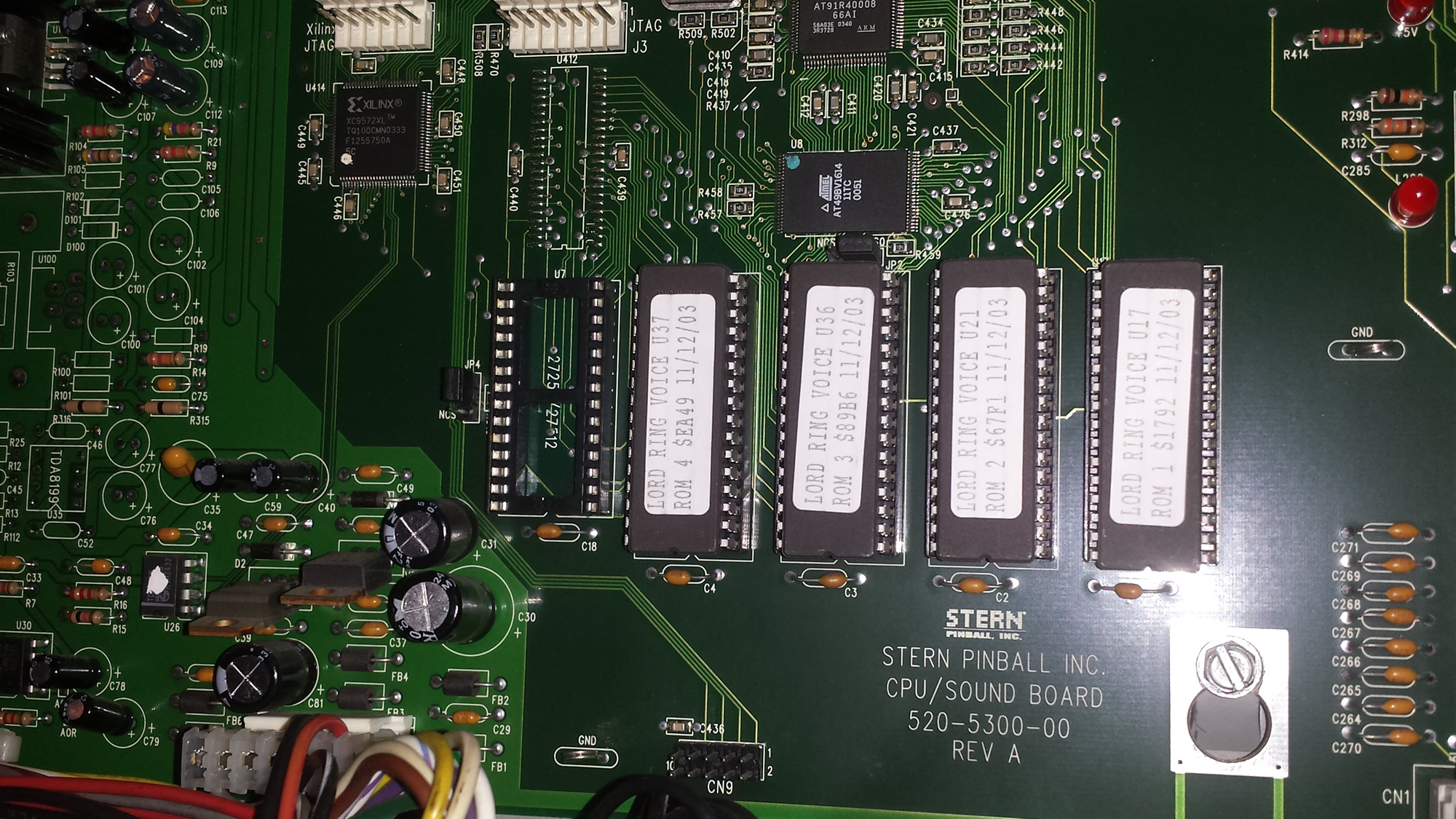
7) Turn off the pinball machine. Remove IC U7 and set it aside being careful not to damage it. Insert the OS 8 Bootflash IC – check orientation. Next, three jumpers must be moved. These jumpers are small plastic tabs that contain a metal connector inside. Carefully move them to the new position as described in the Service Bulletin. Note: We had on jumper where the plastic cover came off, leaving the metal connector in place. Jumper JP2 might be difficult to remove because of its location between two chips.
8) With the OS 8 Bootflash IC in place (Photo 7) and the three jumpers moved, turn on the pinball machine and observe LED 1. The LED will start flashing irregularly. At one point, it may ‘start flashing continuously’ (as about a flash a second), but be patient and do not turn it off. This process will take several minutes. If the machine is turned off too soon, it may become ‘bricked’ (an unconfirmed risk). When it is finished, LED 1 will rapidly flash continuously. Do not be impatient. Let it run.
9) Turn off the machine, remove the OS 8 Bootflash IC and return IC U7 to its original socket – in the same orientation. Return the jumpers to their original positions. Turn the machine on and count the number of flashes on LED1. After the initial flash, there should now be 8. If not, repeat steps 7 – 9.
Installation – The Hardware
The hard part is done! Now, just mount the shaker, the circuit board and make the wiring connection.
the coin box area.
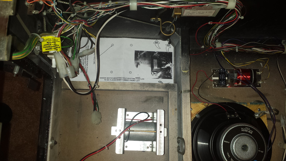
10) Remove the pinballs and playfield glass. Raise the playfield up and against the backglass. Remove the coin box. To the left of the coin box is the area to install the shaker motor (Photo 8). The template maybe supplied by the shaker vendor. Place that to the left of the coin box area as shown. It is important to drill the holes precisely in the center of the template. It is suggested that a small drill be used initially, then drill the final size from below (or both above and below) to prevent ‘blowout’ damage as the drill breaks through.

11) Determine the location of the shaker circuit board. The board must be positioned to clear the shaker motor with the cover on and not interfere with the wiring or the tilt mechanism (to the right). In my case, we turned the white plastic cable guide (seen at the top) around 180 degrees to raise the wires to make room for the board. My vendor supplied proper length screws to attach the board. Check to insure that they will not go through the cabinet and cause damage to the outside.

12) Install the T-nuts from the bottom by tapping them into place.
13) Prior to installing the shaker motor, make the electrical connection. The short red wire from the circuit board connects to the 20V DC power supply which is conveniently at the coin door. [Note: This is the AC side of the rectifier of the 20 VDC power supply. The voltage present will be about 16 VAC.] There are two coin door interlock buttons. These disable the higher power voltage from the playfield when the coin door is open. It is important to connect the shaker to the 20V supply after the switch, so power to it is turned off when the coin door is open. The circuit diagram (pg 108) indicates that the ‘WHT-RED’ wire is always hot, while the ‘RED-WHT’ wire is switched off, so connect the shaker to the red-wht wire.
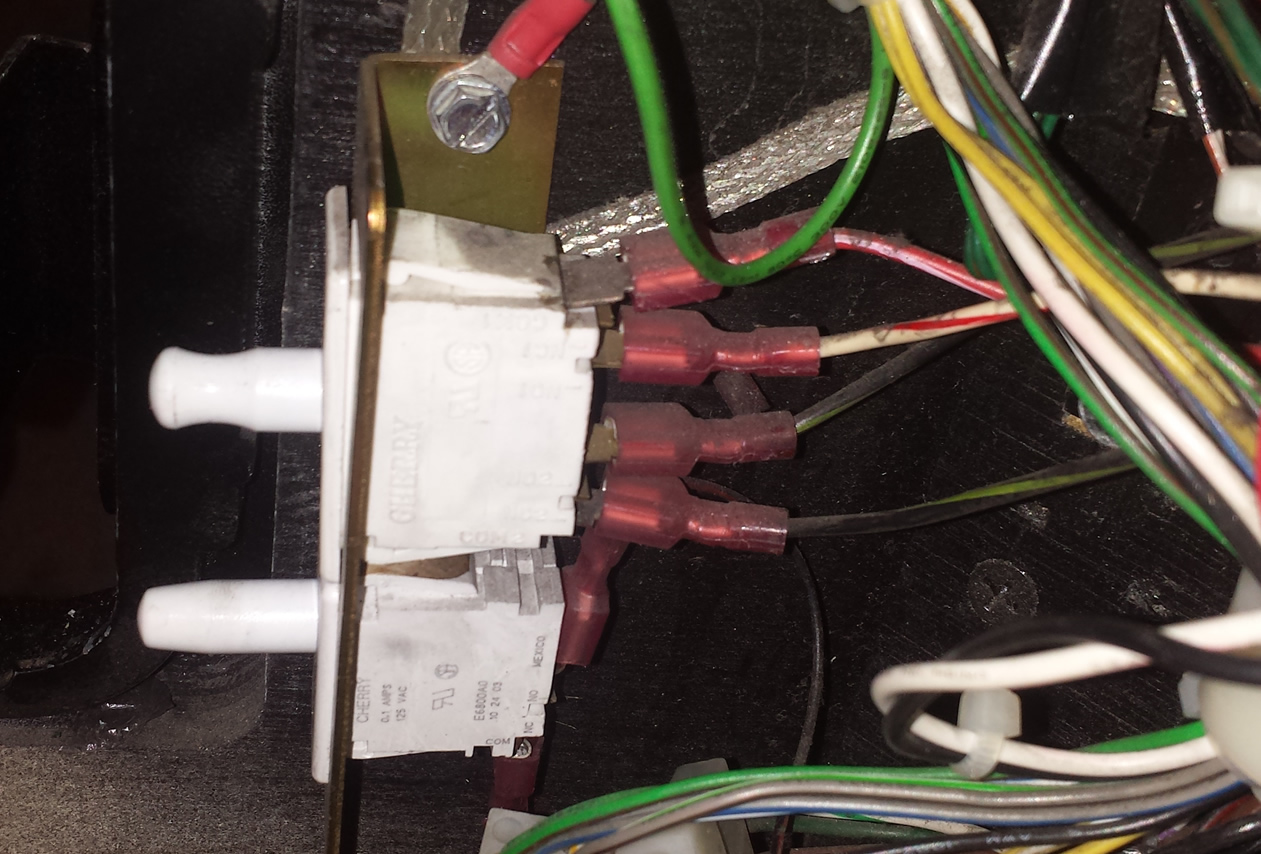
For safety reasons, it is important to connect the shaker motor to the side of the switch that is disabled when the coin door is opened.
14) After confirming that the electrical connection is removed by the door switch, connect the power wire from the shaker circuit board to the switched power wire from the machine. We elected to cut and splice the wire above the circuit board.
Note that many of these shakers have a plug for easy connection to Stern pinball machines that are made to have shakers. Lord of the Rings was not manufactured that way. So it is necessary to cut the plug off and make a direct connection – unless one wants to install a reciprocal plug in the machine to connect to.
15) Install the shaker cover. We found it necessary to move the pendulum tilt ring a little so that the machine could tilt – the bob hit the cover of the shaker without hitting the ring. There was enough adjustment with the ring to do so without drilling new holes, but your situation may vary.
Caution: Never operate the shaker without the cover in place.
16) Run the other, much longer wire, through the cabinet and up to the backbox. Use the cable guides to keep the wire in place.
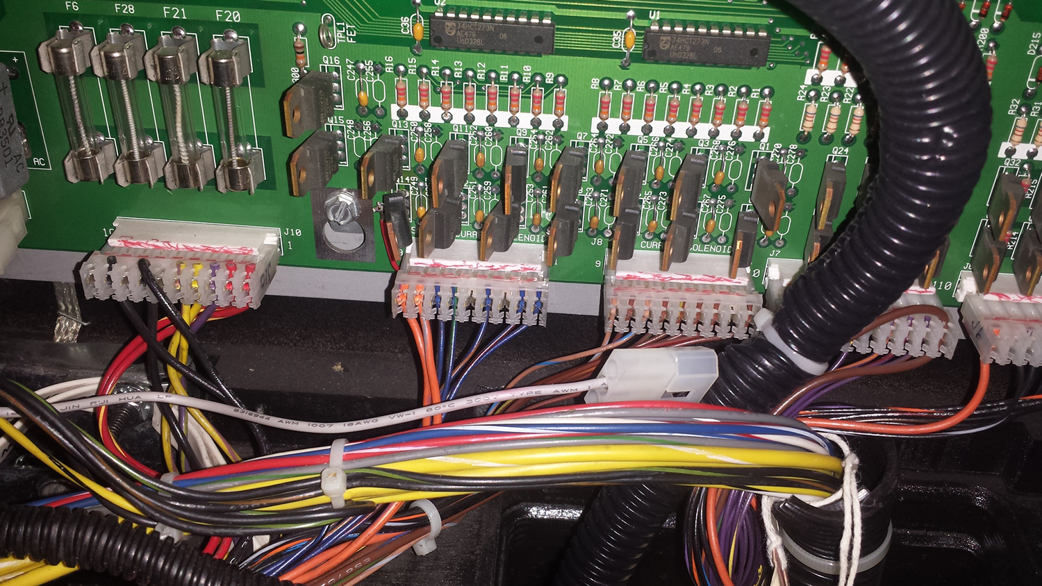
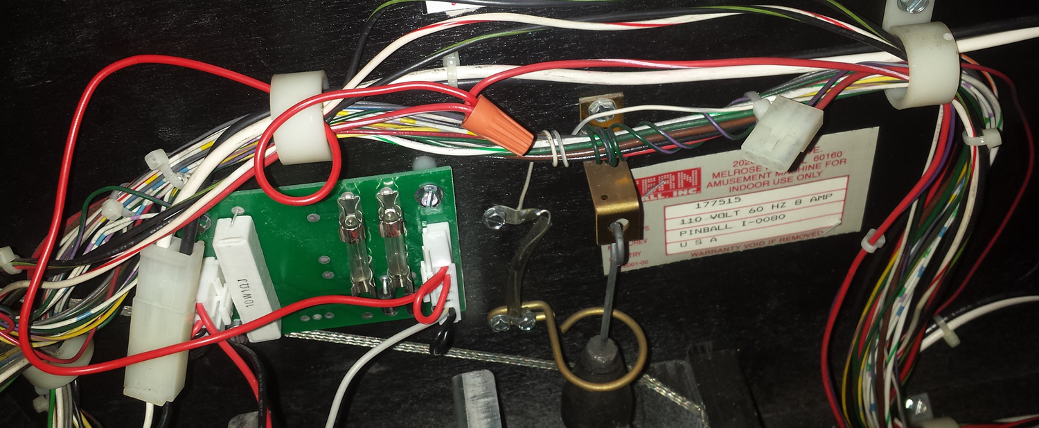
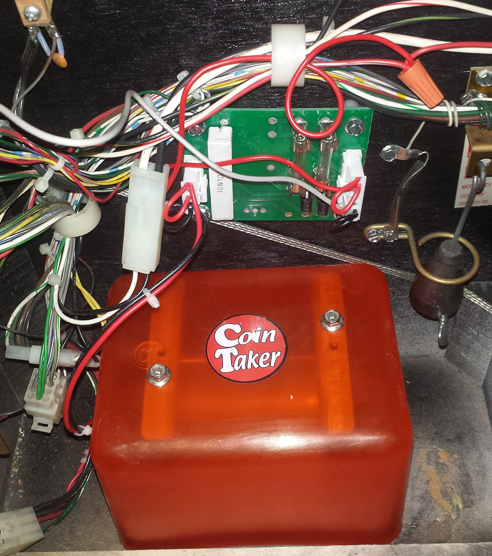
17) In photo (14), note the wire with the connector below the circuit board. That is the final connection from the shaker. It has a plug in the end. Cut it off. Identify plug J9 on the I/O board. Counting from the right, there is not a wire in the 5th position. That is where the shaker motor is connected.
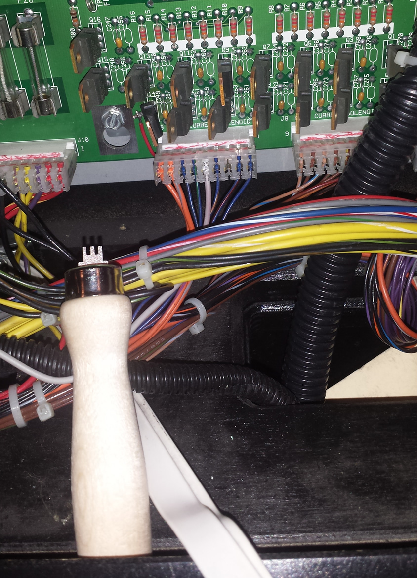
18) Remove plug J9 from the circuit board. Place the wire from the shaker in the empty 5th position from the right. Align the end of the wire to be just inside the plug (it makes insertion easier). Using the IDC pusher tool, press firmly and insert the wire into the connection. Optional: confirm that the wire is connected to the plug using your DVM set to resistance.
19) Plug J9 back into the I/O board. There are no adjustments or setting required or possible for the shaker. Turn on the pinball machine. The shaker motor will activate on certain action.
Comments
We are always looking for comments, including suggestions, improvements, errors, etc. for this page (see below). We are certain we have not thought of everything and there maybe mistakes.
If you have a specific question about your game that does not directly apply to this page, please see our FAQ section.
Copyright 2014 – 2021, all rights reserved.
Great article, thanks. There is one thing that I would love to see clarified. It says:
“The latest that the early (2003) can run is 10.00. 10.02 is needed to run the shaker motor.”
How do you know if a game cannot run 10.02? I’ve looked around and can’t see anyone going in to this.
A good question. The only way the original 2003 Stern Lord of the Rings can run 10.02 is if the machine has been upgraded to the operating system (OS) 8. As it says in step 9) “Turn the machine on and count the number of flashes on LED1. After the initial flash, there should now be 8.”
If your machine on startup flashes only 7, then the operating system has not been upgraded. It will be necessary to purchase the proper ICs and follow steps 1) – 9) to upgrade the OS to 8.
Based on your comments, we changed the wording a bit to try to clarify. Please let us know if this helps.
So I have a friend who bought a SAM shaker kit, upgraded to the LE 10.02 ROM and 10.00 display, upgraded the boot flash, ran the red shaker wire to the top interlock red/white wire and ran the brown wire to pin 5 on J9. Now, when the interlock switch is closed, the shaker runs constantly. Double checked that the game is running on the 10.02 code in the settings. Only different thing any the game is that the driver board is a rottendog.
We don’t have a lot of experience with Rottendog on LOTR, but know of no reason why it should not work the same way. They likely use FETs in the drive just like Stern did.
It is Q12 that should turn the shaker on and off. If it has failed shorted, then the shaker would stay on all the time. We suggest that you check that.
We also suggest that you unplug J9. J9-5 is the connection for the new shaker. When this is unplugged, the shaker should stop. If it does, then maybe that FET is defective. You could test it.
The other possibility is if the software was damaged or not installed correctly, then maybe the software locks that (normally unused) transistor on? We honestly don’t know and have no way to test that theory.
But if you find unplugging J9 stops the shaker and Q12 is not defective, then it is either a board or software issue. Since the original Stern software does not have a way to turn the shaker on or off, that theory would have to be tested through trial and error.
You could also try a factory reset by turning it off and removing the batteries (assuming you don’t have NVRAM installed). If you have NVRAM installed (and you should), then go to the service menu and do a factory reset.
Let us know how it goes.
I’m having an issue with the upgrade where my fuses in the shaker motor board and blowing after 30seconds – 2mins. Is this likely a bad resistor at Q12?
The shaker also seems incredibly strong. I installed a shaker controller which seemed to do nothing on any setting and the fuses kept blowing with this installed or not. Could the controller not function correctly again if there was a bad resistor in the chain?
Unlikely, but possible.
Why would the shaker continue to run for this long?
Generally, a shaker will only run for a few seconds.
It could be that the supplier for the shaker motor has installed a slo blo (SB) fuse. This fuse maybe selected so that the shaker motor can run for a few seconds but the fuse blows if the motor stays on.
If the motor stays on while playing the game, then something is wrong. Either there is a wiring error or the control transistor Q12 is shorted. If Q12 is shorted, you should replace it with an IRL540, which is the replacement for the transistor STP20N10L used in Lord of the Rings Whitestar driver boards.
Update – reading through some of the additional information on this website and read this
“The first thing to know about checking for a short is that 9 times out of 10 the problem will be caused by a diode, bridge rectifier or transistor. And since you’ve read our Tutorial on Diodes and Transistors you know how to check them, right? ”
so I will do some more digging. Thanks!
I would suggest looking at our previous comment on this matter. If the shaker is staying on for long periods of time, you are right, that driver transistor is suspect.
The question becomes, why is it bad?