Introduction

Connectors consist of the following part: 1) Header pins, 2) Plug, 3) Crimp Connector, 4) Wire.
The header pins are soldered to the circuit board. There is usually one pin removed. This is the ‘key’ and it prevents the wrong plug from being used.

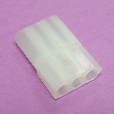
The plug is the plastic housing where the wires are inserted.
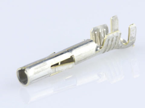
The crimp connector is the metal connector attached to the wire, then inserted into the plug housing.
The crimp itself is the act of bending part of the connector to wrap around the wire.

Most of the connections on solid state Williams/ Bally / Stern / DE / Sega / Gottlieb (Sys 3) circuit boards are either 0.100 (small) or 0.156 (larger) connections.
Understanding How A Crimp Connection Works

A crimp connection consists of two separate crimps: One to hold the insulation, and a second to hold the wire. The insulation is held for strength. The wire is held for the electrical connection.
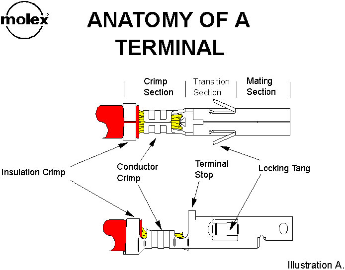
When the crimp is made, the connector is wrapped or folded on these two parts of the wire. For the connection to be right, there must be enough wire stripped to just work under the inner crimp. This is important so that wire does not insert into the connection too far. Or that insulation will not be under the outer crimp. If too little wire is exposed, then the electrical connection will be poor.
For more information, visit the Molex website.
Where To Buy
The most convenient places are pinball parts supply places. These include: Pinball Life, Marco, Big Daddy, The Pinball Resource, etc.
Electronics Suppliers offer a more complete selection of parts. These include: Newark, Mouser, Jameco, and DigiKey.
Where possible, we list the manufacturer part number and you can use that to search at the site of your choice.
Types / Sizes
The most common crimps from wire/ plugs to circuit boards are the 0.156″ crimps. Those are the ones that you will find burned out on Williams / Bally WPC GI circuits as well as Bally and Williams power connections.
Smaller ones are 0.100″ crimp connections. They are used for connections on early games, especially Bally and Stern pins, but were largely abandoned later on as being unreliable.
Plug to plug connections are usually 0.084″ or 0.093″. These connectors are generally used for power and either connect wire to wire, or wire to a large circuit board.
0.062″ were also used but are now obsolete and hard to find.

Early Bally and Stern rectifier boards located in the cabinet used 0.084″ ‘Mate-N-Lok’, Molex Series 42024 / 42023 connectors that are especially difficult to find. Look for these at Big Daddy, Action Pinball, and Marco.
Note that Gottlieb used edge connectors in their earlier solid state games and they are not being addressed here.
Crimper To Buy


The most common crimping done in pinball is 0.100″ and 0.156″. These are the plugs that go to the circuit boards. There are instances where 0.093″ are also used, but those are mostly (but not always) plug to plug.
Pinball Life has a good selection of crimping tools. There are two tools (0.156″ for one, and 0.100″ for the other one) that are less expensive non-ratcheting tools that are good options for the person who does not do much crimping.
For crimping, if you are going to be doing this a lot, then select a ‘ratcheting‘ tool. They are easier to use and give more reliable crimps. They are not as easy to find and getting one that will do 0.156″ and 0.100″ is not easy. Pinball Life had one in stock?
For our money, the best for the light user is the Hanlong Tools HT-225D. This has a ratchet system that is found usually only on the more expensive tools. Sadly, as of March 2023, this tool is no longer available on Amazon. Here is a similar one. And the same part number here.
There is something that looks similar with an identical part number available at Newark Electronics, but we have no experience with it. The drawings look identical to the Hanlong product, so we are hopeful. And here is the identical part number at Amazon which looks like it should work. Please let us know if you try these.
Professional crimpers include: HTR-2445 for 0.156 by GC Electronics, and HTR-1031 for 0.093 connectors. Find those at the parts supply companies.
Molex crimpers are great, but expensive. They are generally available at electronics supply houses such as Newark, Mouser, Jameco, and DigiKey.
Plug Supplies Needed:
| Note: Many of the part number reference a GPE – Great Plains Electronics part number. Sadly, GPE is shut down. These part numbers seem to be manufacturer part numbers and can be used to find alternative supplies. |

Note that there are other size connectors in your pinball machine, but these .0100 and 0.156 are the most common ones in Bally, Stern, Data East / Sega and Williams games.
Gottlieb uses edge connectors in System 1 and System 80 games. Replacing those connectors is not covered here.
Prior to starting, obtain the following supplies: header pins, plug housing, and crimp connectors.

-
- Plastic plug housing Part Number: CS156-20-LR works for 20 pin 0.156. Part Number: CP100-20-LR works for 20 pin 0.100 (search “Molex 0.156” and “Molex 0.100”). Pinball Life, Marco or Big Daddy for “connectors” as well at Newark, Mouser, Jameco, and DigiKey. Note that you do not want IDC, only Molex.
- Header pins (Either 0.156 Part Number: 26-48-1241; or 0.100 Part Number: CH100-40T-0.318 or 0906270160 for 40 pin; 22-28-4361 for 36 pin). Also from Pinball Life, Marco or Big Daddy. Locking header pins are used by the manufacturer. Non-locking is fine for home use but locking might be better.
-

Trifurcon Style
0.156 crimp connectors. 22-26AWG (Part Number 08-50-0185 or 0008500185) , and 18-20AWG wires (Part Number 08-52-0113 or 0008520113). Pinball Life and Marco seem to have only one type and do not specify wire size. Big Daddy has a selection for smaller wire sizes.
The electronics supply houses have the two different sizes; 0008500185 for 22-26AWG or 0008520113 for 18-20 AWG. Be certain to get the Trifurcon style and the right size for the wire size. - 0.100 crimp connectors (Part Number: CH100-40T-0.318 or 08-52-0118) at Pinball Life or Marco as well as the electronics suppliers. There is only one wire size, 22-30 AWG.
-
- 0.084 crimp connectors (Molex 02-08-1004 female, 02-08-2006 male) are available at electronics suppliers such as Mouser (female, male) and Newark (female, male)
- Polarity or Keying Plug (for the ‘key’). Part number 15-04-0297 for 0.156. Or 15-04-9209 for 0.100. Search ‘Keying Plug’. A dab of glue can be used instead, but these plugs are handy. Pinball Life and Big Daddy and the electronics parts suppliers.
Keying or polarity plug.
Note, please install this. We have seen games literally burn because someone left out this plug. - Crimper (see ‘Crimper to Buy’, above).
- 0.084 crimp connectors (Molex 02-08-1004 female, 02-08-2006 male) are available at electronics suppliers such as Mouser (female, male) and Newark (female, male)

There is also an extraction tool available from Marco, or search for part number: 11-03-0016 for 0.156″. This tool is handy to remove crimp connectors from a plastic plug. However, it is not too difficult to remove connectors using a small screwdriver – just crush the tab of the connector in the side slot of the plug, then pull carefully on the wire.
Also available is a kit containing most of the parts needed, Part Number: 76650-3008.

Note: Many suppliers such as Pinball Life and Marco sell IDC plugs. Those are the style originally used by most pinball manufacturers. They do not use crimping, but the wire is force inserted into a plug. It also requires a special tool or this one. We do not recommend IDC connectors. They are less reliable than crimped connectors. However, if you have the IDC tool, these are fast to put together. Don’t try to use a screwdriver to insert the wire.
Supplies for Plug to Plug Connectors
-
- Housing for 0.084 connectors is available at Marco, as well as at Mouser and Newark.
-
- 0.093″ crimp connectors (Molex 02-09-1104 female, 02-09-2103 male) are available at Pinball Life and Marco as well as at Mouser and Newark.
-
- Housing for 0.093″ connectors is available at Pinball Life, Marco, as well as at Mouser and Newark.
Replace the Header Pins
SS Pinball machines have connectors on every board. A sure sign that it is time to replace a connector is when it burns. When replacing these connectors, it is important to replace both the plug and the pins on the circuit board. If the pins on the board are not replaced, that new plug is likely to burn up again.
Replacing the pins on the board is pretty straightforward: remove the existing pins by desoldering. We find it easy to heat each pin with a soldering iron and pull each individual pin out one at a time with needle nose pliers. Then clear the solder holes with solder suckers. Insert the new pins. All done.
Caution: In many of the boards, there are through hole connections and above / below traces. You must know the proper soldering / desoldering techniques to not damage the board when removing the header pins.

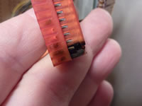
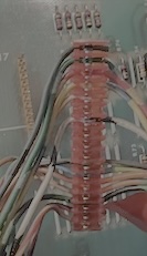
Look very carefully at the plugs. Even a slight discoloration like on this one pin will mean a drop in voltage or a lousy ground. And this can cause all sorts of issues in the game such as rebooting.
Unfortunately, the header pin might be damaged from the heat and have to be replaced, too.
Crimping – Repin the Connectors

Select the proper size (0.100 or 0.156) plug housing with the correct number of holes in it. If there are too many holes, cut off the extra ones with fine wire cutters.
Next, hold the new one next to the old one and mark up the new one. We place an ‘X’ on the spots that do not get a wire, a line for where the key is located. This helps to insure that we don’t put the wire in the wrong hole. Note that the ‘key’ is where there has been a header pin removed on the circuit board. That makes it impossible to insert the wrong connector. We also like to mark the first and last position.
Next, remove one wire from the existing plug. Most plugs used by pinball manufacturers were not crimped in place. They are IDC and the wire is pushed into a pin. These are easy to remove: just pull on the wire. If a standard crimp connection, cut the wire at the plug.
Cut off a small section that is damaged. Remove the right amount of insulation to expose the proper length of bare wire (see ‘Understanding A Crimp’, above). The amount of bare wire needed is to insert far enough to reach the inside crimp. The second crimp should catch the insulation.
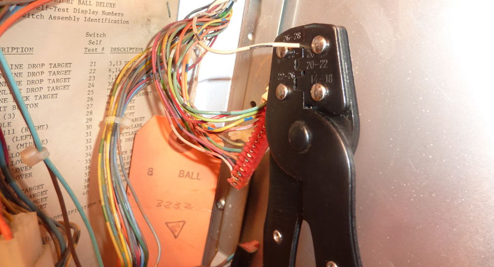
Grab you crimper and insert the crimp connector into the proper slot. The crimper listed above has only two slots. The smaller is for the 0.100 connector and the larger for the 0.156. Note that there is a correct direction for the connector to point. On this crimper, the wire comes in from the left.

On this ratcheting crimper, close the handle one click. This will hold the crimp connector in place (on non-ratchet crimpers, it will be necessary to hold the handle closed partially to hold the metal connector in the tool).
Next, insert the wire into the crimper. Insert the wire so that the stripped portion goes into the inside crimper, while the outside crimp holds the insulation (see photo ‘Anatomy of a Terminal’ above). Then squeeze the crimper. A ratchet crimper will then release. Non-ratchet crimpers will be necessary to judge the right amount of force.
Inspect the connection. If not done properly, remove and start over. Expect a high failure rate at first, but don’t get discouraged. It takes practice, especially with less expensive crimpers.

The crimp has a small tab. That keeps the connection inside the plug. Grab the new plug, carefully identify where the wire should go, and insert the wire with the crimp into the plug. Make certain that the side with the tab is facing the side of the plug with the small slots.
Once the wire and crimp is inside the plug, it should not come back out. If it does, carefully use your fingernail or small screwdriver to bend this tab further out.
At some point, you may find that what looks like a perfectly good crimp is not. After inserting the crimp into the plug, the wire comes right out. To remove the failed crimp from the plug, use a small screwdriver and, showing no mercy, smash down that tab on the plug. With some small amount of violence, it will be possible to remove the connector and try again.
Repeat one by one with each of the next wires. Be sure to follow your marking and skip the positions on the plug where there should not be a wire. By doing one at a time, you are going to make a perfect copy of the original plug and you are now an expert.
Two Wires or Through Wires
Many of the original IDC connectors had a wire going into and out of a single connector – a ‘through wire’. Sometimes those wires continued to a second connector on a single plug, or continued back out into the wiring harness.
Crimp connectors are not designed to handle two wires or ‘through wires’.
The ‘Right Way’ to Handle Through Wires
Pull the wire off of the old connector. Cut the wire at this point. Remove the part(s) of the wire that were in the old connector. This has to be done anyway because the old IDC connector can damage the wire.
Strip the ends ~1/4″. Cut a new wire to about 3″ and strip about 3/8″ or so off one end. If possible, get close to the original wire main color.
Cut a section of shrink tubing long enough to cover the junction of these three wires.
It looks better to twist the two original wires together, then twist the new wire over the two old ones – so that it extends out from the original two.
Or twist the original two together and solder / tin them together. Then tin the new wire with solder, lay it over the other two – continuing the line and solder it.
Slide the shrink tubing over the junction and heat it to shrink it in place.
Crimp the new wire into the connector.
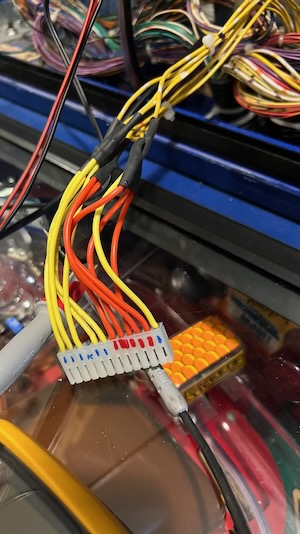
In this example, one wire went through one connector onto a second connector. We connected the original wire to two separate wires. This is the AC connection for the GI’s in a WPC game – those connectors frequently burn.
The ‘Wrong Way’ to Handle Through Wires
We don’t like it but have seen it done.
Crimp connectors have two crimp spots.
Pull the wire off of the old connector. Cut the wire at this point. Remove the part(s) of the wire that were in the old connector. This has to be done anyway because the old IDC connector can damage the wire.
Strip the two new ends. Crimp one wire into the second (interior) crimp but do not let the insulated portion into the first (exterior) crimp. Crimp the second wire into the exterior crimp.
This is technique dependent and may take some practice.
Additional Resources:
Molex Good Crimps
Clay’s Guide to Crimping
Pinwiki Crimping Tools
Comments
Comments, including suggestions, improvements, errors, etc. are welcome (see below).
If you have a specific question about your game that does not directly apply to crimping, please see our FAQ section.