Fixing Data East and early Sega Flippers
B. How Flippers Work
A general overview of how all flippers work.
C. Data East Mechanical Flippers
D. Data East Deger Mechanical
E. Computer Controlled Flippers
1. Data East/Sega
a) The Circuit
b) Troubleshooting
F. Contact Information / Feedback
G. External Links
Initial Troubleshooting

1) One flipper stays stuck up when the power is turned off:
This is a mechanical issue on all styles of flippers. By hand with the power off, move the flipper up and down. If you detect anything other than a smooth movement, it is time to rebuild the flippers. This can be a mushroomed coil stop, burs on the plunger, damaged coil sleeve, and more. If this happens to one flipper, then the others are close to needing a rebuild too, so just do them all.
2) Loss of power in one flipper:
This is frequently the EOS switch (in non-computer controlled flippers). It can mean that the EOS switch is burned up. It can also be physical binding in its movement. It is time to rebuild the flippers. Do all of them. Note that if you have a 1989 or newer Data East / Sega game, the EOS switch cannot affect power (see below).
Don’t replace the coil unless it shows signs of having been overheated. A melted coil will bind up with the plunger.
Coils don’t wear out. Check the resistance vs. the other coil if concerned about damage.
3) Both flippers do not work:
Check the fuse(s) for the flippers. The main flipper fuse is located on the PPB board and, in most cases, is F5, but check the schematic for your specific game.
4) One flipper does not work at all. The other one does.
For mechanical flippers, this can be a broken wire, malfunctioned EOS switch, bad flipper button switch, etc. For computer controlled, also check the fuse(s) on the Solid State Flipper Board.
Mechanical (Non-computer Controlled)
Prior to 1989 and Robocop, Data East had flippers that were just like any other mechanical flippers. They were not computer controlled. All of the power went through the EOS and cabinet switches. They were tungsten and wore out. To fix and / or rebuild these flippers, see the standard flipper troubleshooting and rebuild information.
| Machine DE Sys 2 | Year | Mechanical / Computer |
| Time Machine | 1988-12 | Mechanical |
| Playboy 35th | 1989-05 | Mechanical |
| Monday Night Football | 1989-09 | Deger Mechanical |
| Robocop | 1989-11 | Computer Controlled |
| Phantom of the Opera | 1990-01 | Computer Controlled |
Data East Single Coil Flippers
Deger Design

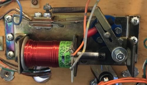
In 1989, Data East introduced a novel flipper design that used flipper coils with only one winding. These coils did not have the traditional two coil (power and hold) design. Instead, there were two power supplies: 50V for power and 9V for hold. The 50V was turned off when the EOS switch opened. This was known as the Deger Design. It was used in Monday Night Football. As far as we can tell, this design was used only in this one machine.
The advantage of this design was the less costly coil and simple design with just a single coil.
Troubleshooting the Deger Design
No Power – Both Flippers
If neither flipper has power, then, check for the 50V at the coil. If missing, this is supplied by the PPB Board. Look for a blown fuse at F5 or burned up bridge rectifier.
If the 50V is at the coil and both flippers do not work, then check to see if the flipper ground relay at the CPU is pulling in during game play. If it is, try grounding the non-banded end of the diode on the flipper coil to see if the flipper works.
Hold not working – Both Flippers
If power works, but no hold on both flippers, then inspect the 4A slow blow fuse under the playfield. This supplies the low voltage used to hold the flippers up.
Data East / Sega Solid State Flippers
Data East beat Williams to the market with the first pinball solid state flipper system. The first solid state computer controlled flipper was introduced 1989 by DE in Robocop in Data East / Sega Version 2.
This design was used throughout all of the Data East / Sega Version 3 and 3b games as well as first two WhiteStar games, Apollo 13 and GoldenEye.
Flipper coils used in all but the earliest pins have two windings on a single coil. One is for power and the second is for hold. Even the ‘modern’ Williams Fliptronics kept the dual coil design. But Data East was able to develop a system that required only one coil for both power and hold, by changing the applied voltage. There are not separate power and hold windings on the coil. As such, there are only two wires going to the coil.

Data East used the pinball machine’s circuitry to control the timing of the high power to the coil. After a short period of time (generally 40 milliseconds), the computer cut the 50 VDC back to 9 VDC to hold the flipper up. Like Fliptronics, the ultimate advantage of this system is that lower power only goes through the flipper and EOS switches, greatly extending their lifetime. Additionally, the EOS switch could stop working and the flippers would continue to operate normally – at least in theory. Data East made a mistake in their first few games (Jurassic Park, Last Action Hero and Tales From The Crypt, and maybe Robocop and Phantom of the Opera) and those flippers will not operate properly if the EOS switches are broken or out of adjustment. Later Data East machines did not have this problem and the flippers could continue to operate with defective EOS switches. How to modify early Data East solid state flipper boards.
Unlike Fliptronics, the EOS switch in DE/Sega/Stern flippers are normally closed, just like regular flipper systems. This EOS switch serves a similar function in that it tells the flipper board if something is forcing the flipper back closed. If the flipper is pushed down (by trapping two or more pinballs, for example), then the EOS switch closes and the flipper board sends another 40 millisecond power pulse to open it back up. For this function to work properly, the EOS switch must be in working order and properly adjusted so that it closes when the flipper is moved back ~1/16″ of an inch.

Data East continued to improve on the circuit and this process was continued after DE was acquired by Sega in the mid-1990’s. Click on the image above, or this link, for detailed theory of operation in the Data East / Sega solid state flipper.
Note that the first two Sega Whitestar games, Apollo and Goldeneye, also use this flipper system and not the later Whitestar system.
The DE/Sega Flipper Circuit

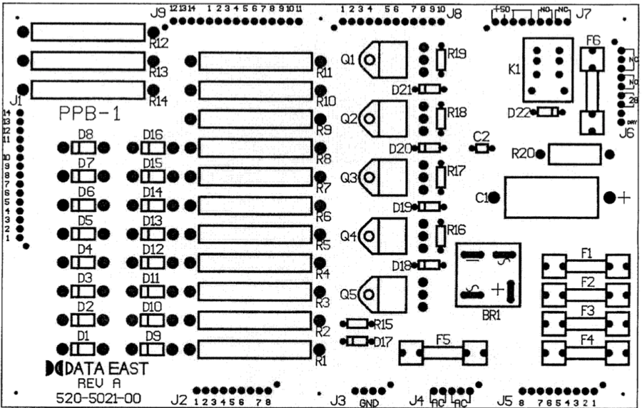
Unlike Williams, Data East / Sega had at least 5 different flipper boards from MPU Version 2, 3 and 3b. On all (? – be sure to check the schematic for your game!), the 50 VDC for the flippers is generated on a separate power board (PPB-1) which is a different board from the power supply board. If there is not any power for the flippers, check the fuses on this board as well as the bridge rectifier BR-1.

The 50 VDC for the power stroke is then connected to the flipper board at CN2, pins 8 and 9. The hold power is supplied via 8 VAC (!) applied to CN2 at pins 6 and 7. The flipper board converts this to DC through a two diodes for each flipper.
Unlike all other games, the 50 VDC is applied to the coil only when the flipper is energized. The coil is grounded via a flipper enable relay located on the CPU board. To test for presence of 50 VDC, it will be necessary to check it on the flipper board at CN2 pins 8 or 9, not the coil.
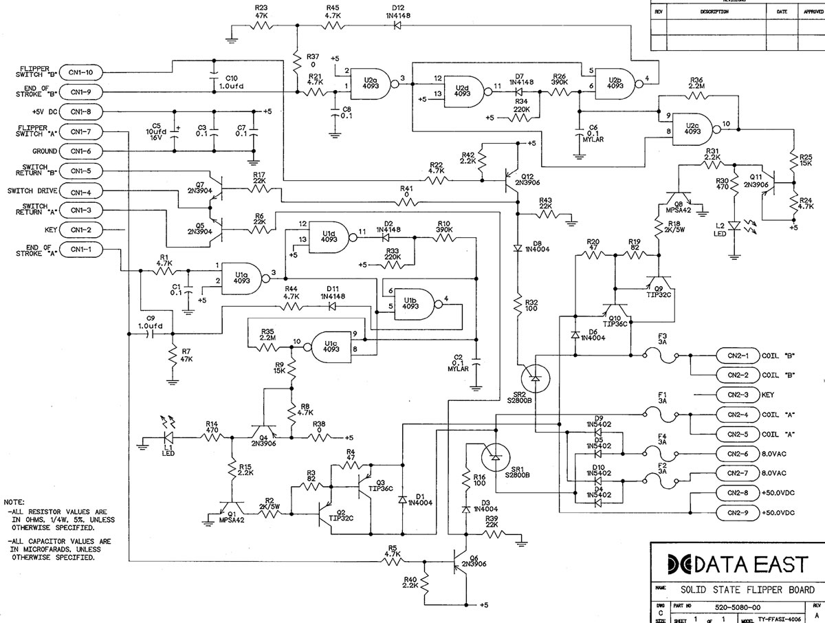
The circuitry for the DE/Sega flipper circuit is far more complex than the Williams Fliptronics board. The circuit, as described in the DE/Sega Flipper Theory photo consists of IC U1 and U2 which are the timing circuit for the power stroke. Q3/Q10 TIP36C ultimately turns on and off the 50 VDC to the coil.

The hold power comes from the 8 VDC which is rectified from the 8 VAC supplied to this board via D4, D5, D9, D10. If the flipper is not held up, check the AC and DC voltages. Q6/Q12 and SR1/SR2 apply the 8 VDC to the coil.
Three Flipper Circuits
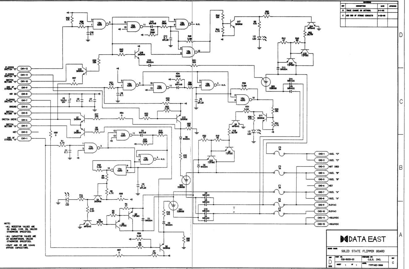
The circuit board for three flipper games contains the same circuit design as those used in two flipper games and works the same way. The third flipper is usually designated as Coil ‘C’. The only difference is that Col ‘C’ does not have an EOS switch. Considering the only role the EOS switch plays with a flipper is to add power when trapping the ball(s), this does not seem to be an issue with the way upper flippers are designed to be used.
Troubleshooting DE/Sega Flippers
If the flippers do not work at all, check the operation of the relay on the CPU board. This relay grounds the coils (the opposite of what happens on Bally / Williams pins where the relay applies the voltage to the coils).
For the power circuit, the following components need to be tested:
| Coil | TIP36C | TIP32C | MPSA42 | 2N3906 |
| A | Q3 | Q2 | Q1 | Q4 |
| B | Q10 | Q9 | Q8 | Q11 |
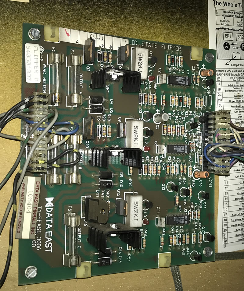
| C | Q16 | Q15 | Q44 | Q17 |
Check that there is 50 VDC coming into the flipper board at CN2. Check there is 8 VAC at CN2 (measure AC across these two wires). The positions on the plug depend on whether using the 2 or 3 flipper board.
Also check the fuses and their fuse holder clips as these are known to fail. Check for ~8 VDC at the band side of diodes D9/D10 and D4/D5. On early games, defective EOS switches can cause issues, but always clean and adjust the EOS switches anyway. Note that there is not an EOS switch on DE/Sega upper flippers.
The LEDs on the boards confirm that the flipper buttons are being pressed and also should confirm that circuit up to the 2N3906 transistor is working.
Usually, when the power circuit fails, it is the TIP36C (Q3, Q10 or Q16). Test the TIP36 transistors using the normal transistor / diode test. Values of 0.5 to 0.7 are good. If that tests good, check the TIP32C. It is less likely that the MPSA42 is defective. If the 2N3906 is not working, then the LED indicator on the board should not be working.
Always check and compare the flipper coil resistances. We like to unplug CN2 when performing this test to insure the circuit board does not affect the reading.
Troubleshooting the Hold Circuit
There are two or three hold circuits depending on the generation of DE/Sega board:
Coil A – Q6 & SR1
Coil B – Q12 & SR2
Coil C – Q18 & SR3
There are three separate two diode full wave rectifiers. Each fuse covers half the wave for a separate diode for each flipper. If a fuse blows, it will affect the hold circuit for each flipper.
If the power works, but the hold does not, it is the 8 VDC portion of the circuit. It could be SR1 (or SR2, SR3 for the other flippers). It could also be the pre-driver Q6 (or Q12, Q18). In the low power portion of the board, it is possible to use a digital probe to compare the working side vs. the non-working side of the circuit. It may also be possible to use a voltmeter set to DC to measure the changes in the +5 V DC.
Note that SR1 – 3 are SCRs and usually do not go bad. If the SCR is bad, apparently the cross reference is MCR12MG. That is available via Mouser, and Digikey.
In the Coil A circuit, the flipper button activates Q6. Q6 then activates SR1 the low voltage which stays on as long as the flipper button is pushed. If either Q6 or SR1 does not work, the hold function of the flipper will not work.

To test this portion of the circuit, pull out your Digital Probe and connect it to ground and +5 V DC power. Test the base of Q6. It should switch from high to low when the flipper button is pushed. If no, then there is a connection issue to the flipper button, a broken trace / solder joint, or R5 or R40 are bad (highly unlikely).
Next, connect your Digital Probe to the lead of Q6 that is connected to R39 and D3. Press the flipper button again. If the digital probe reading does not change, then Q6 2N3906 is defective.
If the output of Q6 changes with the flipper button, check for continuity to the input of SR1 which is via D3 and R16. If they are good, then SR1 is defective. But these SCRs are generally more reliable than Q6 2N3906.
2N3906 is a PNP transistor TO-92 package. It is available from typical electronics supply houses as well as Marco. SR1 is a S2800B SCR which is available from Marco. The late great GPE lists an alternative as MCR12MG, which is available from the usual electronics supply houses.

Note: Coil B is almost identical to the circuit for Coil A. Coil C is a little different as the signal for the hold circuit comes in through U3a. However, if the power portion of this flipper circuit is working then U3a must be working. After that, the hold circuit for Coil C works the same way as Coil A.
Comments
Comments, including suggestions, improvements, errors, etc. are welcome (see below).
If you have a specific question about your game that does not directly apply to solid state flippers, please see our FAQ section.
External Links
Copyright 2006 – 2025, all rights reserved.