How to Interpret the early Bally / Stern Switch Matrix
Understanding the layout of the early Bally Switch matrix and what number each switch is, is confusing. Here is how to make it simple.
Click on the image for a larger picture.
The Schematic

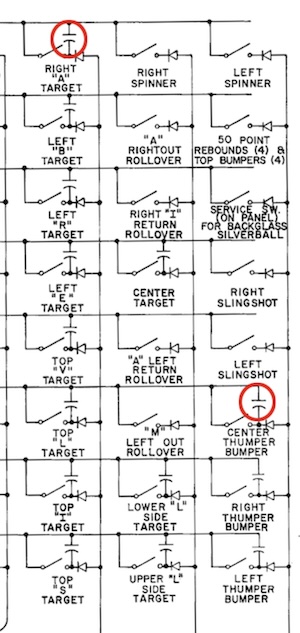
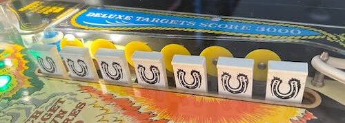
The schematic for the switches are on two different pages which makes it confusing. The first photo is of the playfield switches. This one comes from the Bally Strikes and Spares pinball machine.

Part of the switch matrix is missing. The cabinet switches that are the coin mechanisms (3), and Start switch. Plus the Slam switch. The Tilt switch is usually included in the switch matrix.
Note that all switches in a switch matrix need to have a diode. But Bally skipped on a few switches, notably the coin door switches. The coin door switches frequently get mangled in home use games. If that happens, the switch matrix will malfunction and give wrong switch numbers to the computer. As a result, the game will not play correctly.
The Switch Numbers
Unlike later games, identifying what switch number is which switch is confusing.
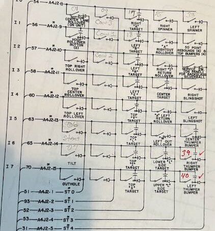
In looking at the first schematic, the lines marked ST0 through ST5 are columns 1 – 6. The lines marked I0 through I7 are the rows. So, unlike later games, there are 5 columns and 8 rows. Later games are 8 x 8.
Additionally, Bally uses a continuous number system of 1 – 48. That means that there is a switch 19 even though there is no row 9.
Plus, the layout is odd and the markings are misleading. A switch at ST1 (column) and I1 (row) is switch 10.
Making Your Own Switch Matrix

To make it easier to understand, we sometimes make a copy of the switch matrix schematic, then mark it up with numbers.
We also copy in the switches in the switch matrix from the cabinet / coin door into the playfield matrix. The result for Bally Silverball Mania looks like this picture.
Now, when testing the switch matrix, a switch number pops up, it is immediately apparent which switch it indicates.
Troubleshooting Bally / Stern Switch Matrix
This guide applies to early Bally and Stern Solid State pinball machines from about 1976 until 1986 or so. This includes Bally MPU AS-2518-17, Bally MPU AS-2518-35, Bally MPU AS-2518-133, Stern M-100 MPU, and Stern M-200 MPU.
Those Switch Capacitors
Bally and Stern used 0.050 uF disc (non-polarized) capacitors on some switches. These are absolutely needed on switches that get only a brief hit from the pinball such as targets. Pop bumper switches have them sometimes too.
They will occasionally short which will cause the switch to read as always on (referred to as “stuck on”). If a switch with a cap (capacitor) appears as closed when it is not, and it has a capacitor, cut the wire near where it is soldered.
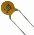
If that fixes the problem, replace it with a 0.047 uF (non-polarized) cap.
If it does not fix the problem, you may just resolder the lead back in place.
Note: These caps do not routinely fail nor do they dry out. There is no reason to go through an old game and replace them all.

Be certain that all switches in the schematic have a capacitor or else that switch will not be sensitive enough for game play.
![]()
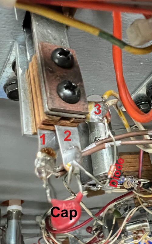
The capacitor must be attached to contacts 1) and 2) in the photo. The column wire comes into 3), the non-banded side of the diode. Tab 3) is not connected to the switch. The row wire is connected to 1).
Note that this target is a modern replacement. The original type target is shown below.
Click on the photo for a larger image.
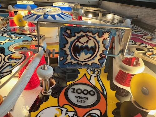
This is an original Bally target. Note that tab 3) is off to the side.
If the capacitor is connected to the end of the diode where the wire comes in, it will always show closed.
The Coin Door
There are several switches on the coin door that are in the switch matrix. The wires to the coin door are stressed by the flexing of opening and closing. If the insulation on one of the wires is scratched and the wire (occasionally) shorts to ground, the switch matrix will go nuts.
The coin switches do not have diodes. If they get mangled, these switches will cause all sorts of errors during game play.
First Step:
These steps are based on the procedure written by terryb. For a complete background of how a switch matrix works, read this.
Any spinners have to be in the down position and the wire connector in its lowest position.
Remove the pinball from the ball trough.
Make sure all drop targets are reset up. Turning on the pinball machine will reset drop targets.
Enter into the Service Menu and the Switch Test (use the red button in the coin door). See your machine manual for specifics.

When in the switch test, a zero should appear. If a switch number shows up, identify that switch and figure out why it is showing as closed.
Also see “Those Switch Capacitors” above.
Note that only the lowest number switch will show as closed. If that one is fixed and another number shows up, that will be a second ‘stuck’ switch.

Grab your switch matrix printout that you made above in “Making Your Own Switch Matrix” above.
You are now in the Service Menu in the switch matrix test and nothing shows as closed. Press one of the switches listed in your switch matrix towards the end. In the example for Silverball Mania, press switch 39 which is the right “Thumper Bumper” (pop bumper). 39 should show up in the display.
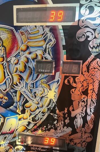
Since the Bally switch test can only show one switch, and the lowest number, this is a great test. If something lower than 39 shows up, you have a switch matrix problem.
Repeat this test for switch 40, which is the upper left pop bumper in Silverball Mania.
 Mark in your paper copy of the switch matrix your results as you go.
In this image, switches 40 and 39 have been tested and only those numbers show up.
If there had been a problem here, a lower number than 39 or 40 would have been displayed.
Repeat this test for all of the switches. If all of the switches show up with the proper number, your switch matrix is working.
Testing the MPU Board
What to do if the wrong number shows up? Or switch does not close?
If the wrong number shows up, then the problem could be on the playfield or on the MPU board.
Caution: high voltages that can kill are present, especially but not limited to on the displays and the power supply board. Read this precaution. The following steps should be done only by qualified personnel.
Remove the backglass. Turn on and boot the machine. Enter into the switch test (see your manual). On the MPU, unplug J2 (playfield switches) and J3 (cabinet switches).
Use a clip lead that can carefully grab the small 0.100″ header pins.

On J2, pins 1 – 5 go to columns 1 – 5 in the switch matrix. Pins 8 – 15 go to rows 1 – 8.
This is where Bally and Stern’s early switch matrix is confusing. Column 1 has switches 1 – 8. Column 2 has switches 9 – 16 (in later machines, this is numbered differently).
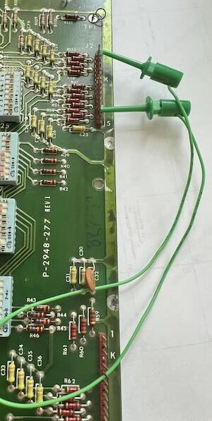
To test switch 14, we want to run a jumper from column 2 and row 6. On J2, that would be J2-2 to J2-13.
Repeat this for any other switches in question.
If the correct switch number shows up each time, then the MPU circuit board is OK. If the wrong numbers show up, repair or replace this board.

If the switch column or row is not working at all or intermittently, check the solder on the back of the header pins. Otherwise, in all likelihood, the problem is with U10, the 6820 / 6821 chip or the socket. Try reseating this IC and see if that helps. Or replace the chip.
Other far less likely possibilities are pull down (R39 – 46) for the columns; or pull up (R31 – 38) resistors, diodes CR1 – 4, 43, caps C27 – C30, C79 or resistors R108 – 111, 132, broken traces bad solder connections.
Testing the Playfield Switch Matrix Wiring

While testing the switch matrix, if the wrong number shows up, it is likely that two or more switches are being read by the computer as closed. As previously mentioned, this Bally / Stern switch matrix test is primitive. Only the lowest number will display of multiple switches.
In the result shown here, every switch in the sixth row show 06 being closed. This indicates a short between the column and row wire, bypassing the diode. Or a mangled coin switch since that does not usually have a diode.
Start by looking at every switch in that row. Look for a short across those wires. Also common is a mis-wired switch where the wire is attached to the wrong side of a diode. Or a cap on the wrong side of the diode. It is possible, but unlikely that a diode is shorted.
For more information on troubleshooting, check out Switch Matrix – Theory and Troubleshooting.