Solenoids in Williams System 3 – 7, 9, 11 and Data East
For information on the Special Solenoids, see this page.
Standard troubleshooting steps are:
 Note about solenoid coils: Solenoid coils, including Special Solenoids may or may not require a diode on a coil. Games before Big Guns (e.g., High Speed, Grand Prix, Fire!) require a diode on the coil. Games starting with Big Guns (and later System 11B/C games) have most diodes on the Aux Power Supply Board. Check your game to see if these diodes are there. If they are, your coil does not need a diode. Flipper Coils always need diodes. |
1) Insure that the coil has voltage going to and from it – both sides of the coil.
2) Check that there is voltage from the coil at the connector to the driver board.
3) Briefly short the connector or tab on the TIP122 / 102 on the board to ground to see if it fires.
Note: If shorting the tab on the TIP fires the solenoid, but none of the solenoids work during game play, it could be a problem with the Blanking Circuit – see below.
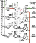
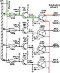
Problem: A single solenoid does not work. Could replace the TIP, the driver transistor, the IC, etc., until it is fixed, but with a digital probe and a little bit of knowledge, you don’t have to. In this example, solenoid 15 does not operate.

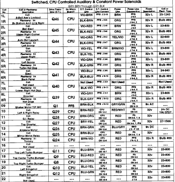
1) Check the manual to see which transistor drives this solenoid. In this example, we are looking at Q14 and Q10 for sol 15. This is found on page 56a on F-14 Tomcat. For other games, look this page on the CPU board.
2) With the power on, connect a clip lead to ground. Ground braid should do. Briefly touch the other one to the metal tab of the TIP transistor. The solenoid should fire. If it does not, there is a wiring / power / coil issue – fix that. If it does, there is a problem with the circuit.
3) Using a DVM, check for voltage between the TIP and the driver transistor (point A). If it is equal to the solenoid power (~ 50 VDC) you have a shorted TIP. Replace the TIP with a TIP102 and driver transistor (see wiring diagram). If you have a shorted TIP, you likely have fried the pre-driver transistor. If there is not 50 V DC at point A, then you might be able to replace just the TIP102 / 122.
If these steps do not work, it will be necessary to work further back into the control section of the circuit.
How the Circuit Works
The Computer Controlled Switched Solenoid Circuit

There are 16 ‘switched’ or computer controlled solenoids. Calling them solenoids is misleading, since they are also used to control flashers. In some System 11 and DE, the transistor can be used to control both solenoids and flashers though a relay that switches back and forth between the two.

The computer controlled solenoid circuit, is activated by a command from the computer. The computer interprets switch closings in the switch matrix in order to determine which solenoid to fire.
The signal from the computer activates an input of a 7408 Logic IC, which, in turns on a pre-driver transistor, which then turns on the full power driver transistor.
The Blanking Circuit
Williams and Data East machines have a Blanking Circuit. The purpose of this circuit is to keep the solenoids from firing if there is an issue with the computer signal. When the pinball machine is turned on, there is a moment before the computer ‘boots’. During that moment, the solenoids will all fire, without any instructions from the computer. To prevent the solenoids from all locking on, the Blanking Circuit sends out a low signal. This lasts for only a moment, then the Blanking Signal should go high.
If none of the solenoids work, it maybe a problem with the Blanking Circuit – although it is important to confirm that the solenoid voltage is working first. If all / most of the solenoids lock on for just a second at start up, then it is likely to be a problem with the Blanking Circuit.
For more about troubleshooting the Blanking Circuit, see below.
The Computer Controlled Solenoid Circuit
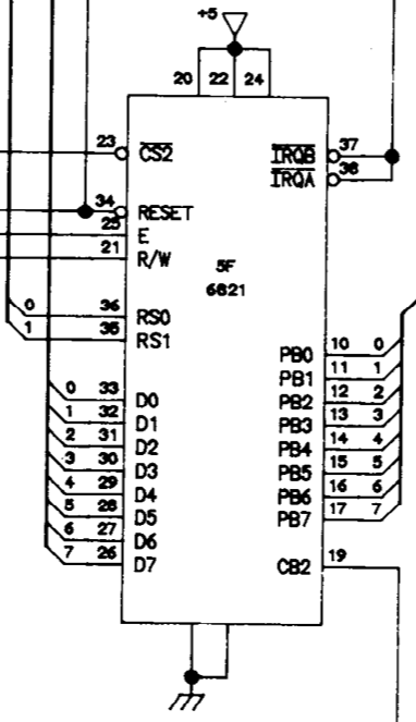
6821 PIA Chip
These solenoids are fired from a signal from the computer. The computer decides whether to fire a solenoid when a certain switch is closed in the switch matrix.
The computer then sends a signal through the data bus to a 6821 PIA (Peripheral Interface Adapter) chip. This chip converts the data from the CPU into commands that turn specific items on and off. This signal from the PIA chip then feeds into the 7408 Logic IC (NTE74LS08).
More specifically – the data comes into the PIA marked with D# (D0 – D7). The output is marked as PB# (PB0 – PB7).
If the solenoid is not to be fired, the output of the PIA is low (L).
The 7408 Logic IC
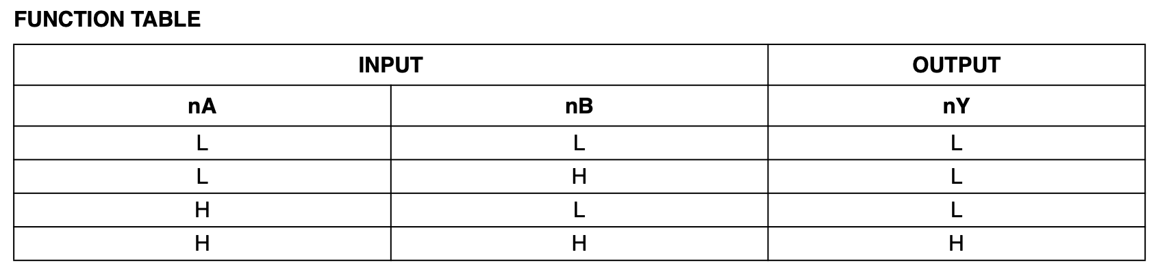
The input to the Computer Controlled Solenoids have a 7408 Logic IC (74HC08). This IC allows the solenoid to be activated by the combination of the Blanking and computer signals. In order for the solenoid to fire, both inputs must be high. Only then, will the output of this IC be high (see last row in the Logic Table).
The blanking circuit goes high to enable the solenoids. The input from the 6821 PIA defaults to low, when the solenoid is off. When the solenoid is fired, the output from the PIA momentarily goes high. Then, and only then, the output of the 7408 Logic IC goes high and the solenoid is activated.
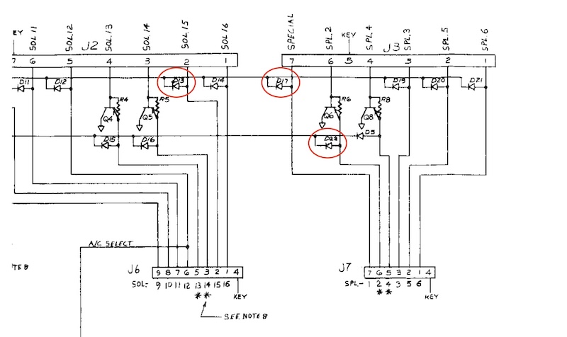
Understanding the Solenoid Circuit Diagrams
In the above drawings on the 7408 Logic IC:
* For both Williams and DE, input 2 is the blanking circuit that should be high; input 1 is the computer signal for this solenoid.
* For Williams 3 – 7 is similar to Sys 11.
Both the Williams and Data East computer controlled solenoids work in the same way. The blanking circuit is high, then applied to the 7408 logic IC (see section above). Following the logic table, for the output of the 7408 to switch, both inputs must be high.
It is important to understand the function of a pull-up resistor and a pull-down resistor. Without a voltage applied to a circuit, the voltage will float – be neither high nor low. This cannot be tolerated in a logic circuit. For a logic circuit to function properly, the voltage must be high (5V DC) or low (0V DC).
A pull-up resistor sets the circuit high (H – 5 V DC) and a pull-down resistor sets the circuit low (L – 0 V DC).
With one input to the 7408 high (blanking) and the other low (computer signal), the output of the 7408 is low (see logic table above).
There is also a 560 ohm pull up resistor connected to the output of the 7408 setting the output high. When the output of the 7408 is low, the IC pulls the +5 V DC to ground. This is important to note in troubleshooting because if the 7408 output is not working, this output will default to high and lock the solenoid on. Note that this pull up resistor is part of a multi-resistor package and not an individual resistor.
When the computer activates the solenoid, that changes pin 1 of the 7408 to high, the 7408 logic table states that with both inputs high, the output is now high (H) (last row of the logic table). This turns on the pre-driver transistor 2N4401 and the TIP122 (or TIP102), shorts the control side of the coil to ground and turns on the solenoid.
Testing the Computer Controlled Solenoid Circuit
An essential tool is the Digital Logic Probe. If you plan on doing any circuit work, you should have one. They are cheap and not difficult to understand.
Connect the Digital Logic Probe

Connect the red probe to a +5 source on this board, and the black probe to ground on this board. Setup the probe as outlined in the Digital Logic Probe section. If you don’t have a digital logic probe, you might be able to get enough information using a voltmeter set to 5 V DC. If auto ranging, it is suggested to set it to fixed range 0.0 V DC.
Determining the Part to Test
It is recommended to run these tests with the 50 V DC removed from this circuit. To do so, unplug 1J11, 1J12, & 1J19 (Williams 9 & 11) or CN11 & CN12 (DE). On Williams System 3 – 7, unplug 2J12, 2J11 and 2J9.

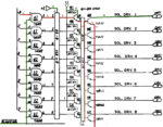
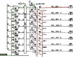
In most Williams 9 – 11 pins, 7408 ICs are used in U17 – U20, U52 and U53. In order to determine which 7408 to test, determine which solenoid or flasher does not work. Then look up in the solenoid table what the control transistor is for that solenoid or flasher. Trace back to the 7408 to identify which IC and which legs to test.
In this example, Solenoid #13 is the Knocker and it is controlled by 7408 U17. The input is pin #1, the Blanking Circuit is pin #2, the output to the pre-transistor is pin #3.
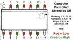
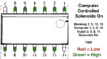
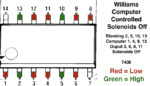
In this part of the board, Data East and Williams use the inputs the same way. The blanking comes into pins 2, 5, 13 and 10. These must be high (on) none of the solenoids will work. If not high, then the issue is with the blanking circuit. The only difference between the Williams and DE setup is that the IC’s are flipped 180 degrees.
The diagrams above are a bit misleading. When testing, set the service menu to test the solenoids. When they are all off, the pins on the 7408 will read as shown in the ‘Off’ image. But while going through the solenoid test, one input will go green at a time – not all of them. Then one output will go green.
When testing, set your digital probe to the input associated with the defective solenoid and insure that the input goes briefly high during the rotating solenoid test. Then switch to the output and insure that the output switches briefly also. If they do, then the IC is working properly and the issue is with the pre-driver or control transistor.
The associated input to outputs are as follows: 1 input to 3 output, 5 to 6, 9 to 8 and 12 to 11. When input 1 is tripped by the computer, the output 3 should also trip – if this IC is working.
Note that if the 7408 is not working at all, then all solenoids will fire. That occurs because the pull up resistor on the output of the 7408 defaults to high. That will activate the pre-driver transistor 2N4401 which will fire the control transistor TIP122 (or TIP102). If all solenoids lock on, then the IC maybe dead, it might not be getting the +5 or ground, or the pull up resistor is defective / not connected.
Note: On some games, one control transistor can control both a solenoid and a set of flashers. If either of those work, then there is not a problem with the solenoid circuit. The problem is elsewhere.
Troubleshooting The Blanking Circuit
Background

On power up, these early SS (solid state) pinball machines would, for a fraction of a second, lock on all the solenoids until the CPU boots. If you are lucky, it is just annoying. But having all the solenoids fire at the same time will put a strain on the power supply and will frequently blow a fuse.
So Williams devised a Blanking Circuit. This circuit will momentarily shut off all of the solenoids. In a perfect world, the pin will start up silently. Then, when the game starts, the solenoids, controlled lamps and displays will be able to be activated.
When Data East entered the pinball business, their circuits ‘influenced’ by Williams designs and included a similar circuit.
What Can Go Wrong
Initially, the blanking signal will be low. This may last for a second or less, allowing the CPU to boot. Once the CPU has taken over control of the solenoids, the blanking signal will go high (4 – 5 volts DC).
If the blanking signal fails to go high, this could be caused by any of the following failures:
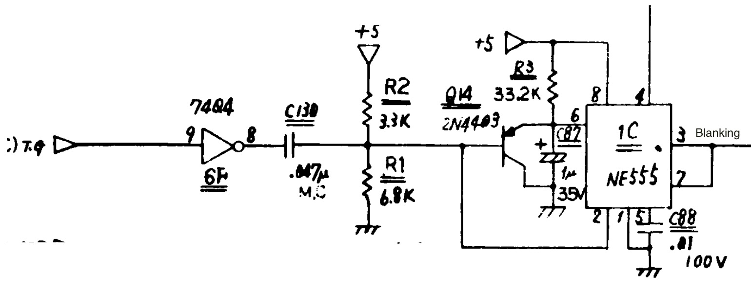
* Timer chip (555 or 556).
* 1 uF cap.
* 2N4403 transistor.
* 7404 IC (least likely).
* In Williams Sys 3 – 7, the board interconnector – although other problems would likely occur too.
On power up, all the solenoids will lock on for a moment and, perhaps blow a fuse, until the computer boots. Williams solved this problem by creating a ‘blanking’ circuit to keep the solenoids from firing. If this system malfunctions, either all the solenoids will fire on start up; or none of the solenoids will work.
Usually, when the blanking circuit malfunctions, all the solenoids fire on start up. For system 11A, 11B and 11C, there are three LEDs (system 11 does not have these LEDs). The right one is the blanking circuit. It should be off momentarily on startup, then turn on and stay on.

To find the defective component, the digital probe can be handy. Using the digital probe, it would be possible to see the signal change at U36 pin 13, then 12), onto Q50, into to pin 6 of U43 and out pin 7 to the solenoids.
Checking these signals with the probe is not easy since they should switch in the first second at start up. However, there is a trick for some. If you are lucky enough to have a CPU with a ‘CPU Test Button’ on the left side, leave the coin door open and press this button. The CPU will repeat a memory test and reboot. Connect the probe as outlined in step 4 above. The following states will occur when blanking is on (right LED on the CPU is on): A=high, B=low, C=low and D=high.
If testing when the pin is fully booted without this switch, the signals are a bit more confusing: A & B are high/low pulse, C is a low / pulse, and D is high.