Advantages of Fliptronics 2 vs. Fliptronics 1
* Separate power supply for flippers
* Coil diode on the Fliptronics Board protects against broken coil diodes.
* Removes stress from Power Driver Board bridge
* Separate fuses for each flipper coil.
* If using an aftermarket (new) Fliptronics Board, use it to full advantage.
* Ground wires from Fliptronics to external Power Supply will no longer be required.
|
If you have installed an aftermarket compatible Fliptronics 1 & 2 Board in an Addams Family, it acts as a Fliptronics 1 board. You will not get the advantage of a Fliptronics 2 board – without these changes. |
Converting The Addams Family to Fliptronics 2
Parts Needed
1) Fliptronics 2 Board. This can be the original Williams Fliptronics 2 board or an aftermarket Fliptronics 2 board. Pinball Life, Marco, Weebly, Rottendog, and others.
2) Wire. #18 gauge. Different colors.
3) Crimping supplies.
a) 0.156″ crimp plug housing (connector female). Typically, get larger sized plugs and cut to size.
b) Include 0.156″ Trifurcon crimp connectors,
c) Polarizing or key pins (a must!).
The most convenient places are pinball parts supply places. These include: Pinball Life, Marco, Big Daddy, The Pinball Resource, etc. Electronics Suppliers offer a more complete selection of parts. These include: Newark, Mouser, Jameco, and DigiKey.
4) Optional – “0.156” Z-connector”. These allow a plug to plug connection. They are getting harder to find. See Marco, Pinball Life and Action Pinball. An alternative is to cut off the original plugs, then connect the new wires directly to the existing one. If doing so, get shrink tubing or similar, then solder.
Introduction
There are three connections needed:
1) Connect 50V AC from the Power Driver Board to the Fliptronics 2 Board.
2) Connect the 50V DC from the Fliptronics 2 Board to the lower flipper coils.
3) Connect the 50V DC from the Fliptronics 2 Board to the upper flipper coils.
Leave the existing external power supply in place to power the under the playfield magnets.
Click on images for a larger photo.
Steps
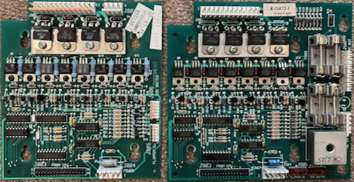
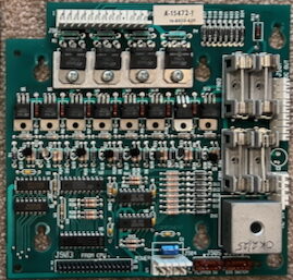
Install the Fliptronics 2 Board (FLP2)
Remove the Fliptronics 1 board located in the top left of the backbox. Attach the Fliptronics 2 board to the screws in the same location. Remove or relocate the two cable ties if necessary.
The plugs in The Addams Family are compatible with the plugs in the Fliptronics 2 board. The smaller plugs move from the side to the bottom. The difference is that the plugs numbers change from J8xx to J9xx.
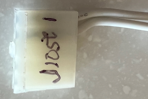
The ground plug J801 is not connected. Put electrical tape over it or mark it “Not Connected”.
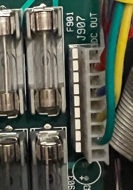
J901 and J907 are empty at this point.
Turn on your Addams Family pinball machine and test it. The flippers should work normally. Turn it off and unplug the machine.
Making the Cables
| Plug number confusion: The original Fliptronics 1 Board plugs are J8xxx. The original external power supply on the middle right plugs are J9xxx. The new Fliptronics 2 Board are J9xxx. Since we will leave the original external power supply in place for the playfield magnets, we will now have two plugs named J901, J902 and J903. |
Cable #1 – AC from Power Driver to Fliptronics
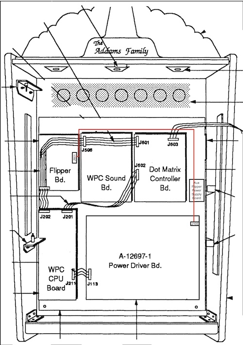
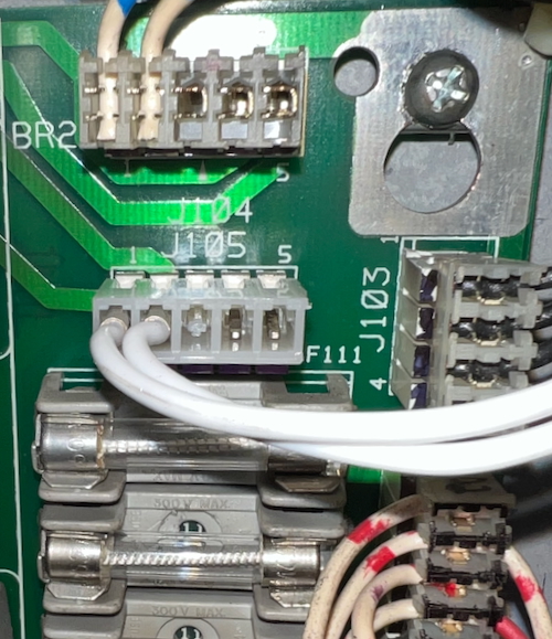
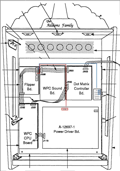
The connection will be from J901 on the Fliptronics 2 Board to J105 (or J104, whichever is empty) on the Power Driver Board.
Both wires should be the same color, perhaps black (AC hot in a house is normally black). We used white wire in our example.
Make the following crimp plug housings
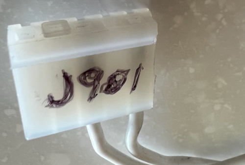
J901 – 5 position plug. Wires at 1 & 3. Key is at 4.
J105 (or J104) – 5 position plug. Wires at 1 & 2. Key plug at position 3.
It does not matter which wire comes from J105 to J901 as this is AC.
Cut two wire lengths of the same color from J901, up and across the top of the backbox boards, across to the right and down to the Power Driver Board, at the top right, beyond plugs J105 / 104. Cut these wires a little bit long.
Crimp 0.156″ Trifurcon crimps to each end of each wire. Connect one end of each wire to J901 positions 1 & 3. Count position #1 as the furthest away from the key (see photo). With the locking side of the plug, #1 is to the right. The key will be second from the left.
If you accidentally connect to 3 & 5, it will short!
Connect the other ends to position 1 & 2 on J105 (or J104). Note that the locking side of the plug should be up and positions #1 & 2 are to the right.
Connect your first cable.
Plug J901 into the Fliptronics board. Run the wires across the top and down to the right and plug into the Power Driver Board at J105 (or J104).
It is a good idea at this point to power it up with this connected at watch the fuses on the top right of the Power Driver Board. If this connection is wrong, the fuse flash will confirm the error.
Hook up your voltmeter and set it to DC above 50V DC. Connect the black end to any ground – the ground braid will do. Touch the various pins on J907. All should read ~70V DC with no load attached.
Turn off the pinball machine and unplug.
Power to the Flippers
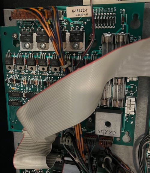
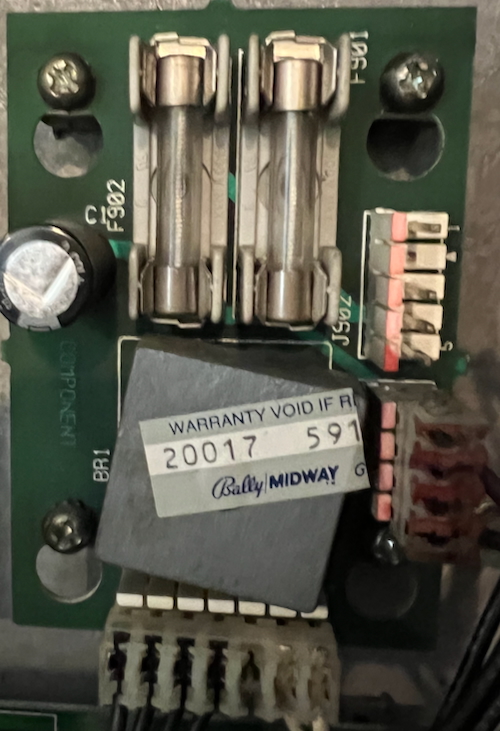
The Fliptronics Board 2 has four fuses. It is important to have one fuse feed each separate flipper coil. It does not matter which fuse goes to which coil. Most games have fuse F901 to the upper right, fuse F902 to the upper left, F903 to the lower right and F904 to the lower left – but we don’t know if that is true for all WPC89 Fliptronics.
All power comes from J907 on the Fliptronics 2 board. F901 is J907-1,2; F902 is J907-4,5; F903 is J907-6, 7; and F904 is J907-8,9. We only used one pin and one wire for each flipper since that was all that was used for the original connections.
The next cable uses a 9 position 0.156″ plug with the key at pin 3. This one plug then feeds to other plugs, one to the lower flippers and the other to the upper flippers.
Cable #2 – DC power from Fliptronics to the Flippers
To power the flippers, we need one plug at the Fliptronics 2 board connecting to two different plugs (not to circuit boards).
One of the plugs is for the upper flippers and that plug is connected to the Flipper Power Supply board.
The other plug connects to the lower flippers and that plug is connected to the Power Driver Board.
To the Upper Flipper Coils
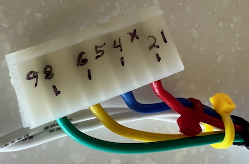
Select a 9 position 0.156″ female plug housing (or cut a bigger plug down to 9 positions).
Compare it with J907 on the Fliptronics Board with the locking side up / left. Confirm that position 3 has the key.
Insert the key into position #3.
| We recommend putting plugs on the other ends from J907 to connect power to the flippers. However, that means you have to have 0.156″ “Z-connectors” to connect the two plugs together (see “Parts Needed” above). If you decided to cut those plugs off and make direct solder connections, ignore making the plugs for J109 (Power Driver) and J902 (External Power Supply). |
The 9 position will have two wires going from J907-2 and 4 to J901 (original external power supply).
Take two different color wires. Run them from J907 on the Fliptronics board, across the top again, and down on the right side to the External Power supply. Leave excess length.
Crimp 0.156″ Trifurcon crimps to each end of each wire.
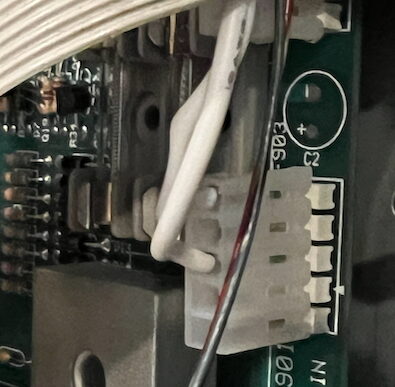
Insert one color into the 9 position plug J907-2. Insert the other color into the 9 position plug J907-4 (the red and blue wires in the photo).
Connection for the Upper Flippers
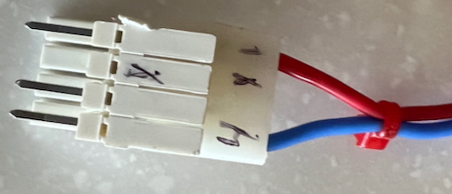
This J902 is the plug from the aux power supply on mid-right of the backbox. Note the “Z-connector” to allow a plug to connect to another plug.
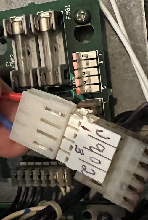
The other end is a 4 position plug with a key in position #2 (see photo). Compare this plug with the one from the external power supply J902. Ours had wires in positions 1 & 4. If yours is different, match this new plug to mate with the wires in J902.
Insert the wire from J907-2 into J902-1 (External Power Supply). The wire from J907-4 goes to J902-4.
Connection for the Lower Flippers
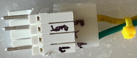
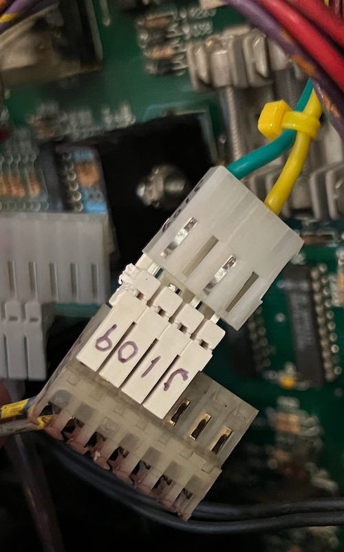
The lower flippers are connected to J109 on the Power Driver Board.
Note that we used a shorter “Z-connector” than the full size of the J109 plug. This was because we were running out. Using a 7-position Z-connector would be better.
J109 plug has only two wires. They are at the 5 and 7 position with the key at J109-6.
Final Connections
Plug the four wire plug into J907 on the Fliptronics 2 board.
Run the wires as shown above.
Unplug J902 from the Flipper Aux Power Supply.
Insert your four position plug with the Z-connector into the plug that your removed from J902.
This plug has wires from J907 – 2 and 4
Insert the other four position plug into the J109 plug. This plug’s wires will match up with the only two wires from the plug J109.
The two wires in this plug are from J907 – 6 and 8.
Your Addams Family is now fully upgraded to Fliptronics 2.