1) How a WPC Flipper Works
2) Flipper Components
B. When to Rebuild
1) Troubleshooting
2) Mechanical
3) Electrical
4) Diodes
C. Rebuilding
1) Tools Needed
E. How To
1) Steps Involved
2) Install EOS Switch
3) Flipper Bat
4) Adjust EOS Switch
H. External Links
Cautions: Must read before proceeding. Machine must be turned off and unplugged.
A glossary of terms used on this page.
Note: Click on any image or links for a larger image.
Skip all of the important information and jump to rebuilding.
Portions of this article was originally posted on PinballRehab.com.
Reproduced with permission from terryb.
Bally / Williams WPC Games with
Old Style pre-Fliptronics Flippers
| Funhouse | 1990 |
| Harley-Davidson | 1991 |
| Bride of Pin*Bot | 1991 |
| Gilligan’s Island | 1991 |
| Terminator 2 | 1991 |
| Hurricane | 1991 |
| The Party Zone | 1991 |
For those games, see Rebuilding Old Style
pre-Fliptronics, see this link. All other Bally / Williams WPC games use Fliptronics flippers.
How a WPC Fliptronics Flipper Works
Williams/Bally computer controlled Fliptronics flippers in the early 1990’s. All machines from The Addams Family on were Fliptronics. This also includes WPC-S and WPC95 machines.
A simplified description of Fliptronics is:
1) Player presses a button that closes a low power gold plated or opto switch to complete the circuit
2) The high power portion of the coil is energized by the computer. This is a timed event not affected by the EOS switch
3) The coil creates a magnetic field, drawing the plunger into the coil, hitting the coil stop
4) The flipper opens, closing the EOS switch (Fliptronics)
5) The computer turns on the lower power coil into the circuit and turns off the high power coil- not because of the EOS switch.
6) When the player lets go of the flipper switch, the spring retracts the flipper, removing the plunger from the coil
7) The loss of power changes the coil into a power generator.
8) The collapsing magnetic field creates electricity. A diode shorts out this power, preventing damage to the circuitry.
There are several advantages to Fliptronics:
* The EOS and flipper cabinet switches are gold plated.
* The EOS switch does not affect the power of the flipper.
* The EOS switch can be broken and the flipper will work almost normally.
* The flipper button and EOS switches have only low power going to them and take a very long time to wear out.
* No capacitor is required on the EOS switch.
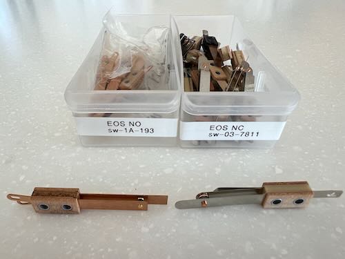
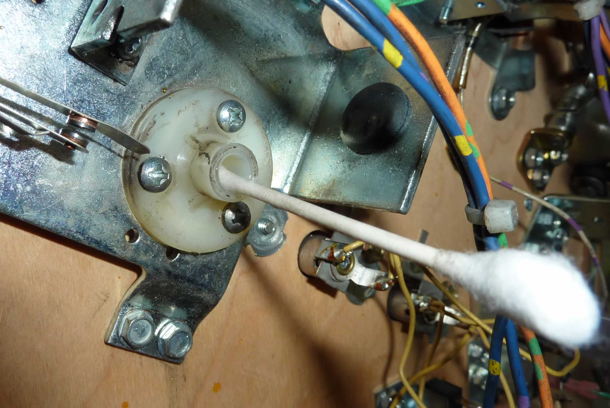
The EOS switch – Fliptronics – normally open and gold plated – no capacitor
The EOS switches should never be filed, but can be cleaned by inserting a business card and dragging it across the contacts as they are held closed by your fingers.
Or they can be cleaned with Q-tips and a small amount of 91% isopropyl (not rubbing) alcohol (Note: flammable – see cautions).

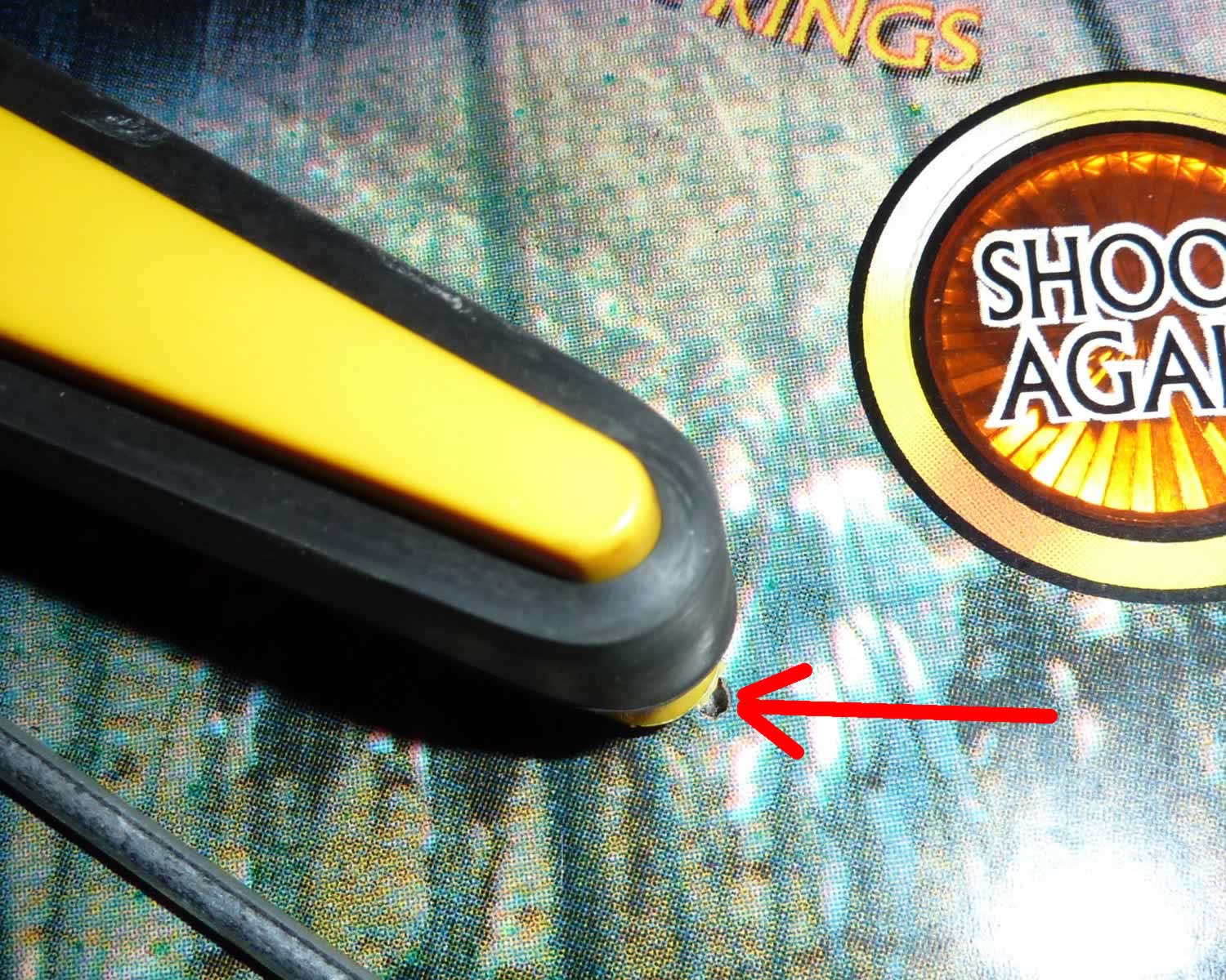
This low power cabinet flipper switch shows almost no wear. It belongs to a Williams / Bally Fliptronics pin.
Many fliptronics games use optical switches on the cabinet flipper buttons.
Flipper Components
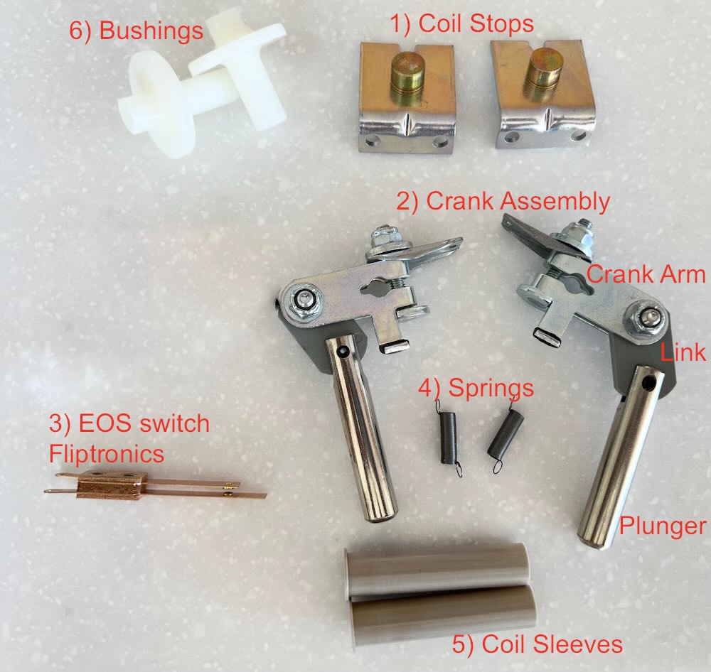 Williams WPC Flipper Parts – Contained in a Typical Kit from a parts supplier.
1) Coil Stop
2) Crank Assembly
– a – Plunger
– b – Link
– c – Crank Arm
3) Fliptronics EOS Switch
4) External Spring
5) Coil sleeve
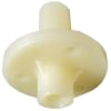
6) Bushing – Optional (usually not included in the kit).
** – New flipper bats (optional – if old ones are damaged or yellowed)
It is only necessary to replace the bushing if it is damaged. They usually do not wear out. Clean the shaft area with isopropyl alcohol and a cloth.
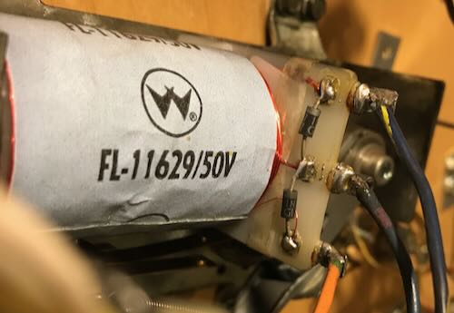
Check the part number on the flipper coils and compare to the manual. If not the right one, order a new coil.
Coils do not wear out. If they appear damaged, typically from overheating, or if the coil sleeve cannot be removed, replace the coil. It is recommended that you test the coils (see below).
Fliptronics flippers do not have nor need a EOS switch capacitor.
The easiest way to purchase these parts is via a rebuild kit.
Pinball Life – Fliptronics
Marco – Fliptronics
An extensive list of game / manufacturer specific parts are on this page.
Included is a description of different coil stops and sleeves.
Troubleshooting Flipper Issues
The most common cause of weak flippers are physical problems than can be easily diagnosed.
Note: Never lubricate any flipper parts.
Mechanical Checks:
* Turn the machine off and unplug.
* Remove the playfield glass. Remove the pinball(s) if planning on raising the playfield.
* Manually move the flipper back and forth. Listen for any rubbing. Be certain that the flipper does not rub the playfield. Pull up on the flipper. There should be a small amount of up / down movement.
* Check for a broken or weak spring.
* Check for wear on the Crank Assembly Link. This is what usually wears out first. If the hole in the link has become elongated, replace the Crank Assembly or purchase a rebuild kit.
If there is play when pulling and pushing from the ends, that saps the power.
* Plunger and/or coil stop become mushroomed. This can cause the flipper to stick open or not move freely.
* If there is any doubt about the wear and tear of components including the Crank Assembly, springs, EOS switch, or Coil Stop, install a rebuild kit.
* Inspect the EOS switch and flipper switch. Because these are low power, they do not pit nor burn. The EOS switch is normally replaced on rebuilding the flippers.
If one flipper is worn out, save yourself the aggravation of having to do this again and rebuild both.
Electrical Problems:
Testing the Coils

* Turn the power off. This procedure is to test the coil wires for shorts or breaks.
* Identify the tabs on the coil where fine wires come in. That is the hold coil. Set the DVM to resistance and the lowest setting.
* Measure the resistance across these two tabs. The value should be around 160 ohms (exact value is not important).
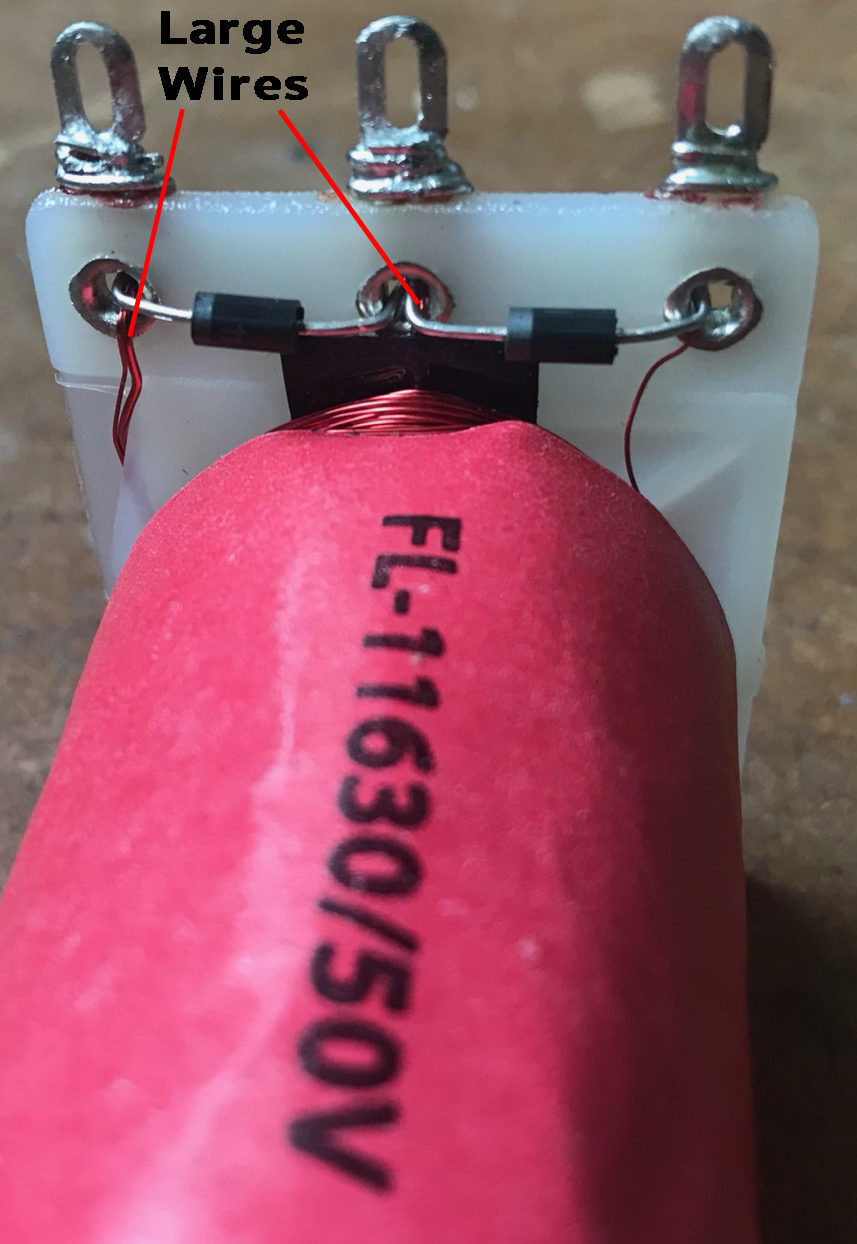
* Identify the two tabs where the thicker wires are connected. This is the power coil. Measure the resistance. The value should be very low, perhaps between 4 – 5 ohms. See coil resistance chart.
* Compare all the flipper coils. If they are significantly different, then one coil might be damaged. A low value could be a partial short. An extremely high value indicates a broken wire. Different coil numbers will give slightly different values.
Note that coils usually do not have to be replaced. When they do, it is because the flipper does not work at all or the coil has been overheated. If it is impossible to remove the coil sleeve, the coil has been overheated and damaged. Replace that coil.
A weak flipper is rarely caused by the coil.
Note: If the EOS Switch is not working in Fliptronics machine, a switch error usually shows when the machine is started.
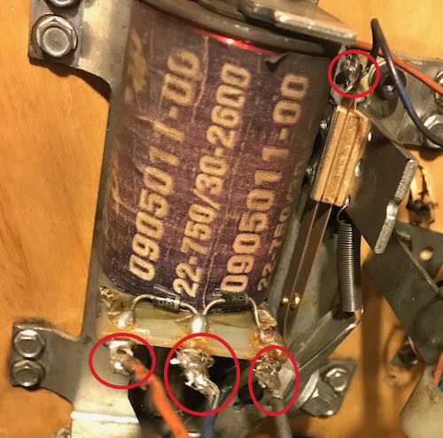
* Visually inspect where the wires are soldered to the coil. It is not unusual to see many of the wire strands broken off. The more that are broken off, the higher the resistance which will reduce flipper power.
* It could be the power supply to the flipper. Check for burnt connectors where the flipper circuit plugs into the power supply board at J901 and J907.
The flipper power supply is on the Fliptronics board – except for The Addams Family that has a separate flipper power supply board. Check the voltage and the condition of the electrolytic capacitors (for leakage or bulging).
The power supply can appear to be normal but fail to supply adequate power (current) when used. This is difficult to diagnose. The power supply can read high (70V DC) when not under use, but drop closer to the spec of 50V DC when the flipper is fired. That is normal.
Flipper Diodes

Note: Fliptronics 2 coils do not have to have diodes on the coils as they are on the Fliptronics circuit board. But most leave them on the coil anyway.
The Addams Family requires coil diodes where a broken diode will blow a transistor.
A diode conducts electricity in one direction only. It is there to protect the sensitive electronics in solid state (SS) pinball machines.
When DC flipper coils are activated, electricity runs through the coil. When the flipper is turned off, the magnetic field around the coil collapses and the coil turns into an electric generator and power runs in the opposite direction. The power generated by the coil can fry the circuit board – usually the TIP transistor.
The diodes conduct electricity one way and short out the collapsing field.
If the coil is installed with the wires switched, those same diodes will conduct when the power is applied to the coil which should blow the fuse, and usually fry the diodes & transistor.
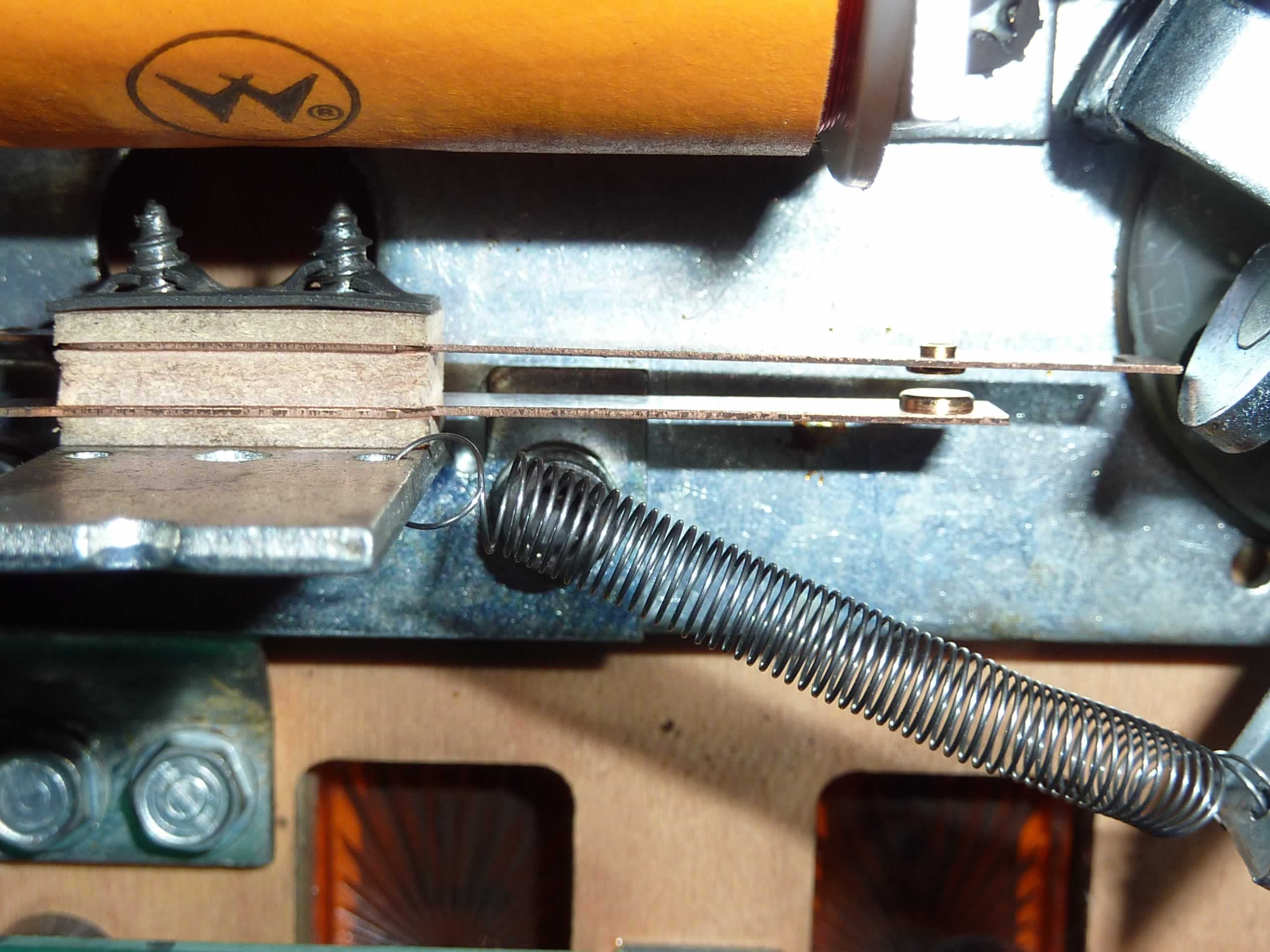
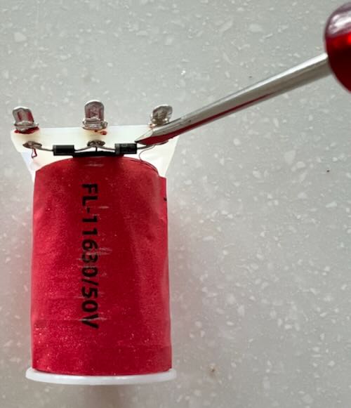
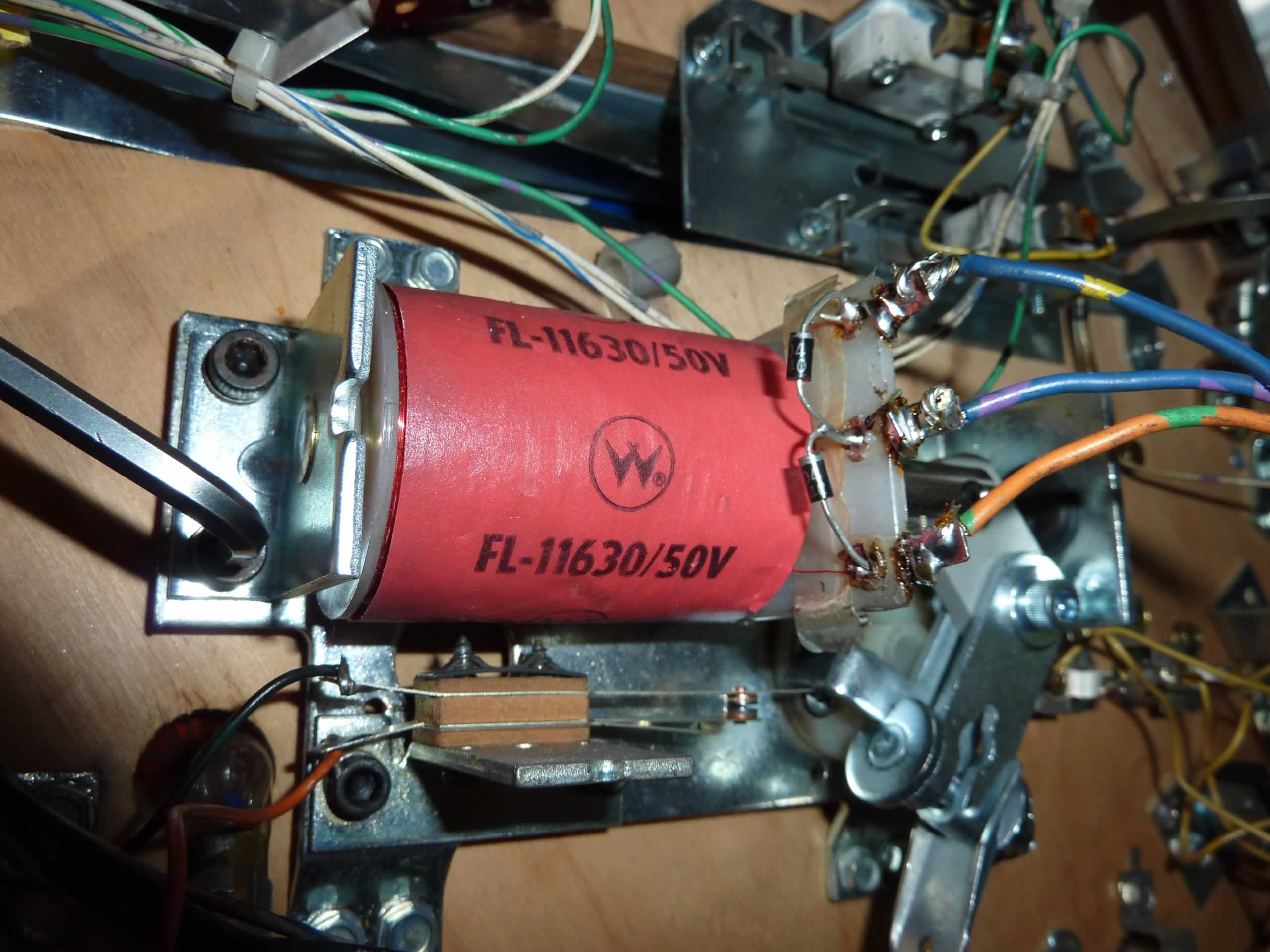
When rebuilding the flippers, take the time to inspect the diodes. Put a little bit of stress on each one with a screwdriver. If they break apart, replace the diode. The diode marking must be in the same direction as the orginal diode (see photo below).
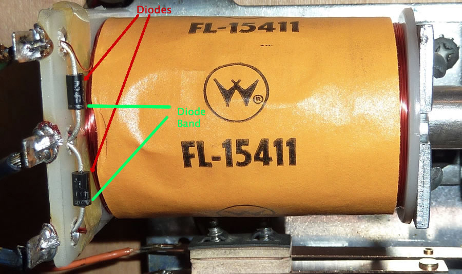
If replacing a coil, be sure to check the diodes on the coil to see if they are ‘pointing’ in the same direction. If they are, connect the wires to the new one in the same order. If the direction of the diodes are reversed, then reverse the wires.
Looking closely at the picture (click for larger photo) shows the bands on the bottom of each coil indicating direction of the diodes.

Note that most new coils come with a 1N4004 diode installed which is good to 400V. If replacing a broken diode, or installing a diode when one is missing, it is a good idea to install a 1N4007. It is rated for 1000V and costs almost exactly the same. Save those 1N4004 diodes for the switch and lamp matrix.
When replacing a diode, it is a good idea to remove the old one. Be certain to pull those diodes against the plastic body of the coil assembly. ‘Hanging in the air’ diodes are more likely to break.
Note that the diodes and tabs should be away from the coil stop. This is to reduce the likelihood of the diode leads breaking. If possible, it is a good idea to flip the coil around with the solder tabs and diodes away from the coil stop.
Rebuilding the Flippers
The easiest way to rebuild a flipper is to order a flipper repair kit from a pinball parts supplier.
Pinball Life – Fliptronics
Marco – Fliptronics
Check out our webpage on Flipper Components as well as your pinball machine manual.
Note that most flipper repair kits do not include the bushings. It is generally not necessary to replace the bushings unless they are worn or damaged. Check the condition of the bushings prior to ordering.
Tools Needed

1) Screwdriver – usually Phillips
Medium and small.
2) Allen Wrenches – usually 5/32″
3) Needle Nose Pliers
4) Wire Cutters
5) Soldering Iron & Solder
6) Nut Drivers and/or socket wrenches. 3/8″ socket to remove the flipper bat.
Optional:

Flipper gauge – Nice to have, especially when doing this the first time. But making sure of a small amount of vertical movement is usually sufficient.
Wire stripper (or similar) – This is our favorite model.
Wire – Nice to have a supply of different color stranded wire around. For flippers, #18 gauge is preferred. Likely will need new wire for the EOS switch.
How To Rebuild WPC Fliptronics Flippers
Prior to beginning disassembly, pull up and down on the flipper itself. Notice that there is a small amount of vertical movement. When re-assembling, it is crucial that there be a little bit of up and down movement on the flipper bat, or the mechanism will bind and not swing freely.
Steps: Caution: Insure the machine is turned off and unplugged.
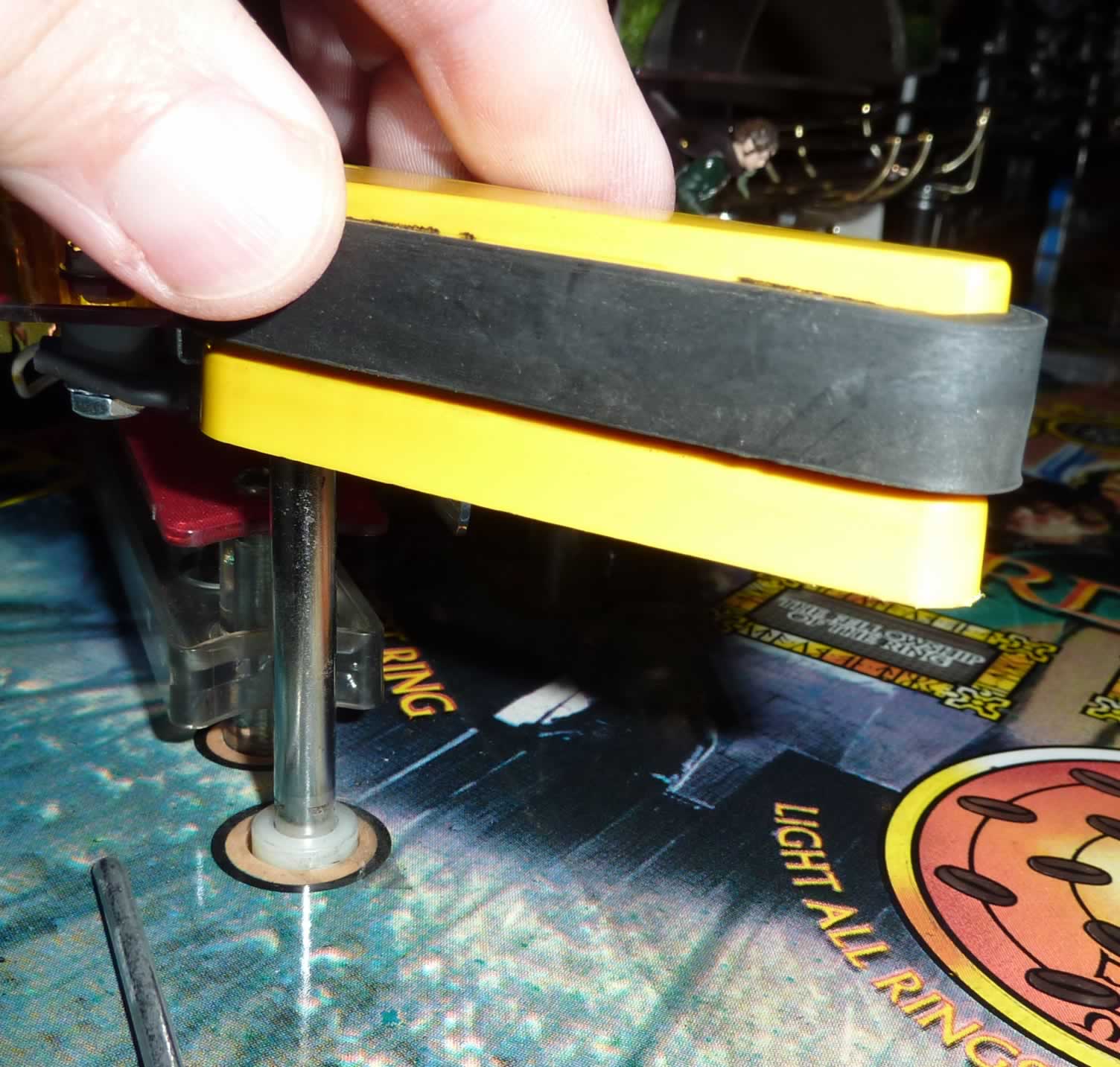
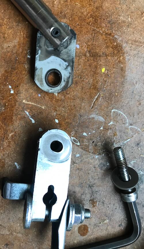
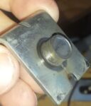
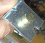
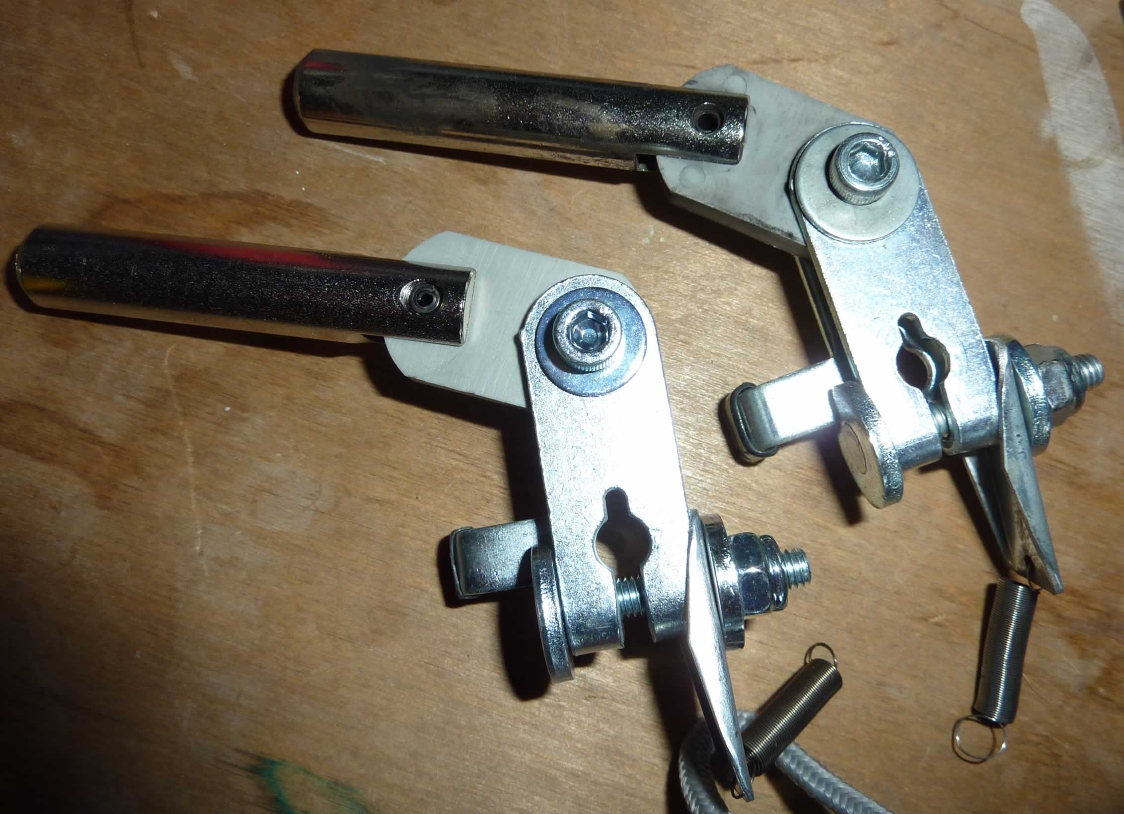
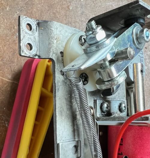
*Remove the flipper by loosening the nut holding the flipper bat shaft.

Some are held in place by a combination of a nut and an Allen bolt like the Williams assembly to the right. Some require only a socket wrench to loosen.
Note: At this point, it is possible to unsolder the three wires to the coil, plus the two wires to the EOS switch, and remove the entire flipper assembly. This makes it much easier to rebuild the flippers.
Take photos to insure that these three wires are soldered to the same tabs on the coil. Wiring backwards will cause a short and destroy the diodes and the transistor.
The wires to the EOS switch can be wired to either tab.
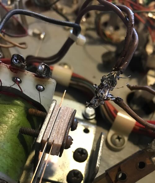
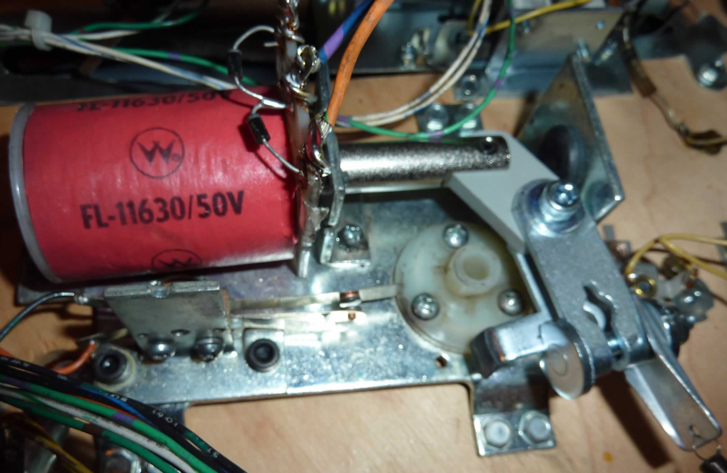
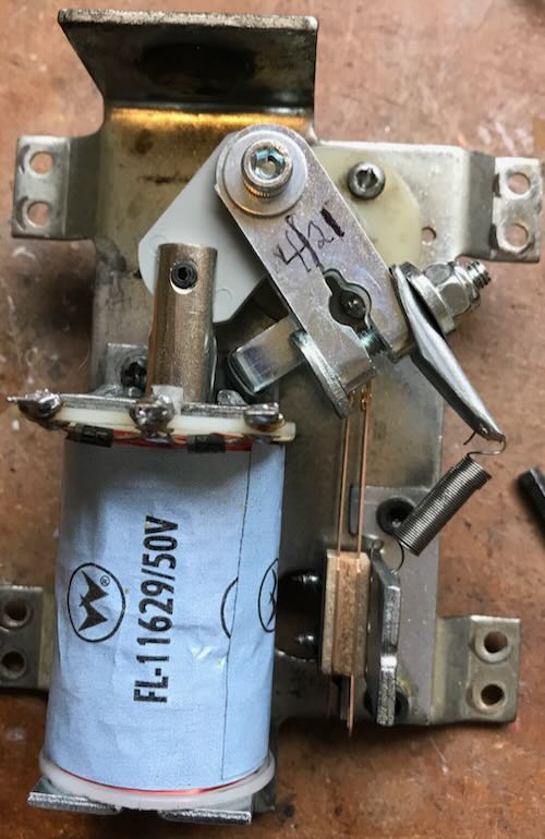
This is a flipper and coil from an Indiana Jones flipper. It is the wrong coil, the soldering is terrible and fraying of the wires require cutting and stripping. Unsolder these five wires and remove the eight screws holding it to the playfield.
![]() * Remove the flipper coil stop (#1 in the above ‘Components‘). This will require an Allen wrench.
* Remove the flipper coil stop (#1 in the above ‘Components‘). This will require an Allen wrench.
* At this point, the solenoid coil and crank assembly will no longer be held in place. Remove the coil from the plunger.
* Use your needle nose pliers to disconnect the spring from the base.

* If still attached, unsolder the wires from the EOS switch. Remove the old EOS switch with a small Phillips screwdriver.
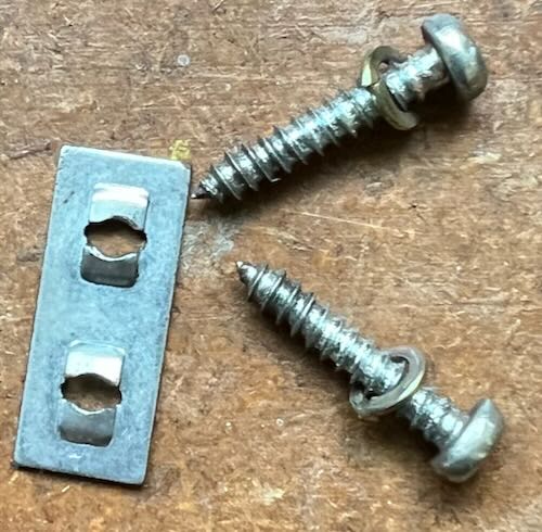
* Set the two screws and the speednut aside.
* Clean out the bushing hole for the flipper shaft. We use several q-tips or a towel and small amounts of isopropyl alcohol. Note, if the flipper dragged on the playfield, likely cause was this worn bushing. Replace it. Most of the time, this bushing does not require replacement.
* Inspect the diodes on the coil. Carefully insert a small screwdriver behind the diode and push slightly to see if it is broken.
If one diode is broken or suspect, replace it.

* Replace the coil sleeve. Insert the new one with the collar on the same side.

* It maybe impossible to remove some sleeves. That is usually because the coil overheated and is ruined. Replace the coil and use a new sleeve.
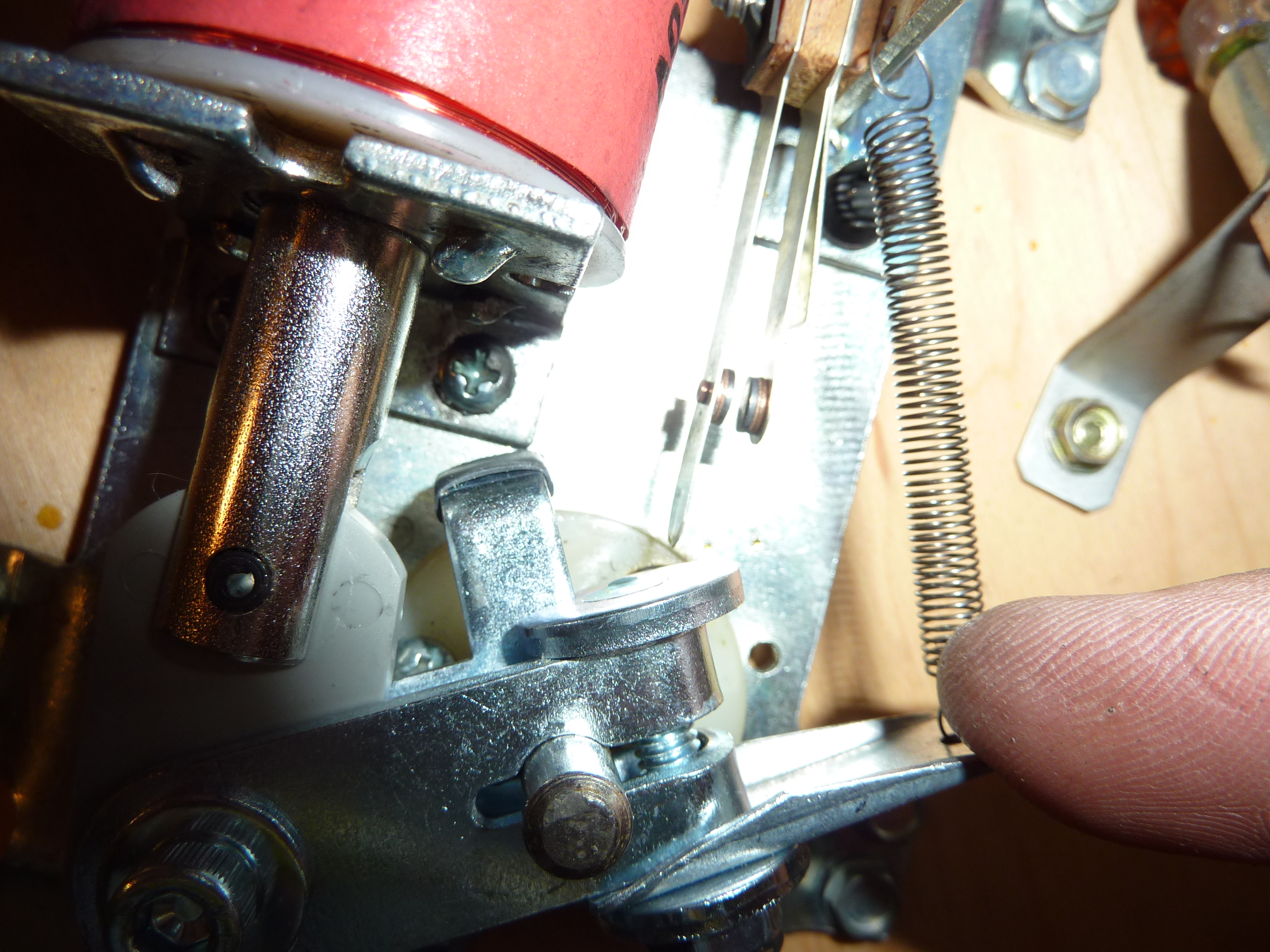
* Reattach the EOS switch. Note that the switch goes on the coil side of the bracket with the speednut holding the EOS switch in place.
The long leaf goes towards the coil so that the switch closes when the flipper is activated.- see photo.
* There is a left and right crank assembly. Compare the new ones with the one you have removed and select the identical one. Attach the new spring to the EOS switch bracket but not the linkage.
* Insert the crank assembly through the solenoid bracket, then into the coil (diode / wire end away from the coil stop).

* If the original coil stop had a washer / spring attached, set it on the new one.
* Hold all three parts together and insert the coil into the new coil stop from step #2.
Attach the new coil stop, removed in step #2, to the base plate.
While holding this all together, manipulate the crank assembly into its proper position so that it is ready to be connected to the flipper bat shaft.
Attach the spring to the crank assembly. One end goes to the EOS switch bracket – there are two small holes to connect the spring. Use the one closest to the crank assembly.
The other end of the spring goes to the tab on the crank assembly.
Adusting the EOS Switch

This Fliptronics EOS switch will be open when the flipper is not in use (normally open) in these Williams / Bally Fliptronics pins.
Note: We found some EOS switches have an oil on it that should be removed. A Q-tip and Isopropyl Alcohol on the contacts will quickly do the trick.
If doing the work on a table (recommended), we also temporarily install the flipper bat to adjust the EOS switch. Tighten it just enough to hold it in place.
For Fliptronics EOS switch: switch is open when the flipper is at rest. Closes when the flipper is fired.
Note that that this is the opposite of what happens with older style full power flippers.
The switch should be adjusted to close when the flipper is up (activated).
The EOS switch should start to open as the flipper just starts to fall back (towards off).
The only purpose for this EOS switch is to tell the computer that a force is pushing the flipper closed (such as trapping 3 pinballs) and the computer increases the power to the flipper. And improperly adjusted EOS switch cannot cause Fliptronics flippers to be weak.
If new to adjusting leaf switches, follow this guide. Note that this EOS switch does not have a stationary blade.
Remove the flipper bat when adjusting the EOS switch.
Re-Installing the Flipper Assembly onto the Playfield

If the flipper has been removed from the game, it is time to reinstall it on the game. Position the bracket so that the four ‘legs’ line up with the screw holes in the game, then tighten the 8 screws in place.
Solder the two fine wires to the EOS switch.
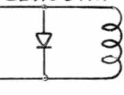
The order / position of the wires on the coil is critical. Wrong position and the transistor on the board and the coil diodes will be destroyed. The schematic is included to help with the wiring colors.
Tightening the Flipper Bat
Insert the flipper bat through the playfield and into the Crank Assembly. Tighten the nut holding the shaft firmly, but not tight enough to prevent it from moving.
Check the flipper’s position in the playfield. It should be possible to swing the flipper bat into various positions.
While holding the flipper mechanism in the closed (at rest – power off position) below the playfield, swing the flipper bat above the playfield. If the bat turns too freely, tighten the screws or bolts holding the shaft in place. If it is difficult to turn, loosen these screws or bolts just a little. Make certain that there is a little up and down movement. Use the Flipper gauge if you have one.

Swing the bat into the desired position. If there are small markers in the playfield, the bat should either point at the marker, or rest on it. If the alignment point is below the flipper, insert a toothpick into the marker and set the bat against the toothpick (without the rubber). If no markers are present, set the bat parallel to the wire on the playfield.
Tighten the bolt / screws on the crank assembly, firmly, but don’t crank it down extremely hard. Too hard is when the gap on the crank assembly begins to close from tightening the bolt.
If after a few minutes of game play, the flipper bat starts to shift position, it was too loose.
External Links
How a Flipper Works – Steve Kulpa’s great explanation. [Steve’s website is down as of 2020. He has allowed us to reproduce it on our website.]
Coil Cross Reference – Extremely helpful information about pinball coils and cross references from Pinball Medic.
Copyright 2006 – 2025, all rights reserved.
Comments
Comments, including suggestions, improvements, errors, etc. are welcome (see below).
If you have a specific question about your game that does not directly apply to rebuilding flippers, please see our FAQ section.