B. How Flippers Work
C. Serial Coils
D. Parallel Coils
E. Computer Controlled Flippers
Solid State Flippers
Note: The following was written to describe how flippers work in early Bally and Stern SS pinball machines. But what follows is largely true for all pinball machines, including EM up through about the late 1980’s.
The following article was originally posted on Steve Kulpa’s Bally Page at stevekulpa.net.
Reproduced with permission from Steve Kulpa.
Written by Steve Kulpa
Note that parts of this have been edited by HomePinballRepair, but the article is still the result of Steve’s hard work.
An Introduction to Switch Terminology

Normally Closed (NC) – Normally closed switches have two contacts that are touching at rest. This switch can be thought of as ‘on’ by default. These contacts are pushed apart when activation occurs. And example is the End of Stroke Switch on a flipper.
Normally Open (NO) – Normally open switches have two contacts that are apart at rest. This switch can be thought of as ‘off’ by default. Most playfield and cabinet switches are Normally Open. This includes stationary targets, roll-over switches, coin and start switches on the coin door and the push buttons on the cabinet that activate the flippers.
How Pinball Flippers Work – Early SS
An introduction of how coils work.
The Bally and Stern flipper coils work off 43 Volts DC (VDC). According to Ohm’s Law, a small resistance draws a large current, and a large resistance draws a small current. This also implies that current flow will always try to follow the path of least resistance (like everything else in nature). Finally, for this example, just assume that current flows from positive to negative (ground).
The Bally / Stern flipper coil has 3 lugs. This is true about most other flipper coils, except newer DE/Sega/Stern computer controlled flippers.
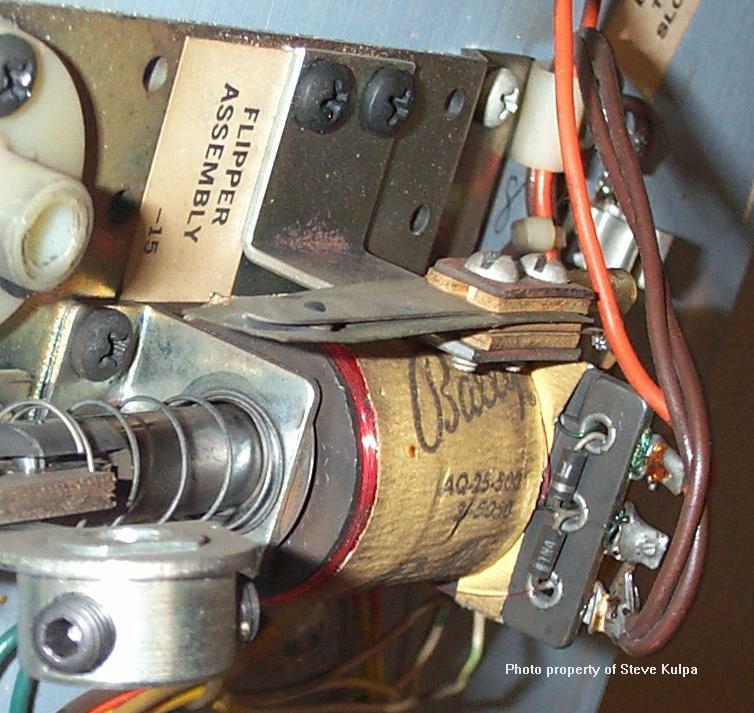
There are two coils in this assembly, a high power and a low power, joined together by the middle lug.
Across the lower power coil is a switch, called the End Of Stroke (EOS) switch. Power is applied to the single end of the low power coil and the single end of the high power coil is connected to the switch activated by the flipper button. The other side of the flipper button switch is connected to ground.
When the flipper button is pressed, a complete circuit to ground is established, and the flipper coils are energized.
Note that between the flipper button switch and the flipper coil is the Flipper Enable Relay. For simplicity’s sake, I’ve not shown this relay in most of the drawings on this page.
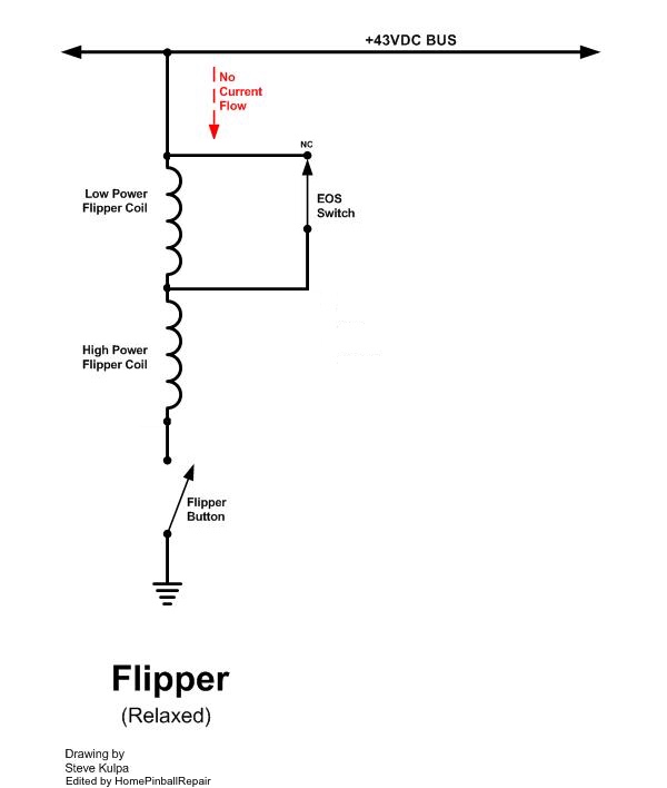
The picture above is a simplified schematic of a single flipper as used in the Bally early solid state machines.
The high power coil has a small amount of wire (500 wraps), which results in a small resistance, around 3 – 10 ohms. The flipper coil in the photo is a AQ-25-500/34-5050. The power side, 25-500 has a resistance of 3.3 ohms. Using Ohm’s law, at 43 volts, 3.3 ohms will draw about 13 Amps, which is quite a bit of current.
The low power coil has over 5000 wraps of wire, resulting in about 265 ohms. At 43 volts, this coil will draw about .16 Amps, or 160 milliamps, which is a whole lot less than the high power coil.
When the flipper button is first pressed, the path to ground is complete and power is applied to the high power coil. The EOS switch is used to bypass the lower power coil, at least for now. With only the high power coil being used, you get a nice strong flip.
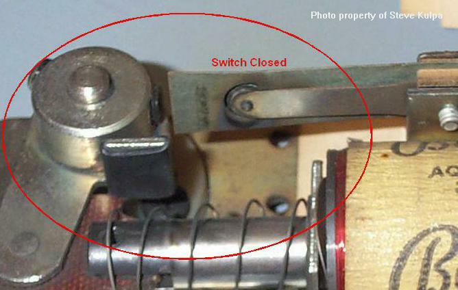
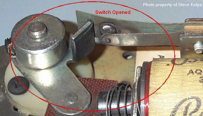
If you want to hold the flipper in the up position to trap the ball, the high power could would eventually burn up, or you’d blow a fuse. A continuous draw of 13 Amps is just too much. To keep this from happening, as the flipper reaches the top of the flip, a little tab on the flipper pawl will open the EOS switch. In the two pictures below, you can see a before and after photo of this phenomenon (look at the black tab thing that pushes the switch):
When the switch is normally closed, it puts a short across the low power coil and most of the current bypasses the lower power coil and flows through the switch (current takes the path of least resistance). So the majority of the current flows through just the high powered coil. This gives the flipper it’s punch.
Then, when the flipper reaches its end of stroke, the tab opens up the switch which makes the current flow through the low power coil IN ADDITION to the high power coil. This adds lots more resistance, which drops the current flow, which allows the player to keep the flipper engaged in the up position without burning anything up.
When the flipper button is released, the path to ground is lost, so the current no longer flows, the flipper coil relaxes allowing the flipper’s spring to return the flipper to it’s down position. The switch again closes and everything’s back to normal.
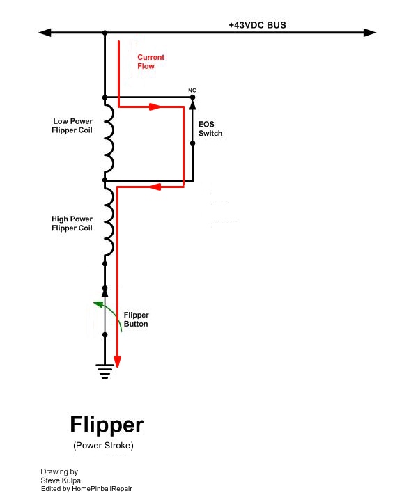
Photo 5, above, is what’s happening just as the flipper button is pushed. Current flows through high powered coil, but the EOS switch is closed so the current flow bypasses the lower powered coil. The high powered coil has a very low resistance, so it draws a lot of current, making for a nice strong flip.
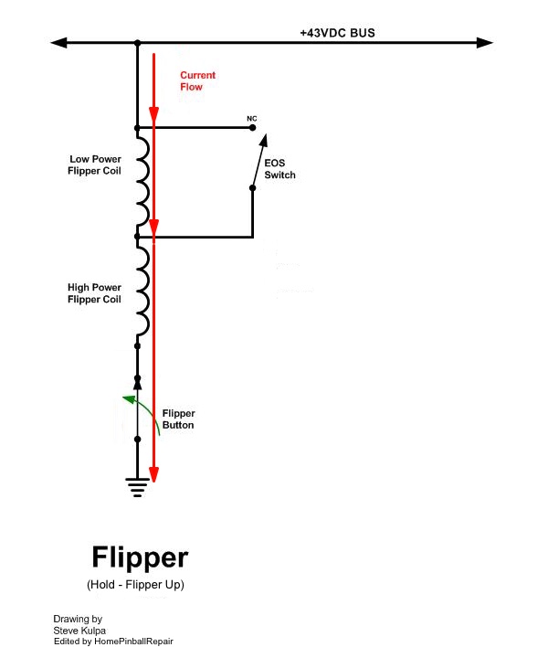
In Photo 6, the flipper pawl has hit the EOS switch and it opens, allowing current to flow through both coils as long as the flipper is in the up position. By including the low power coil, its resistance is added to the resistance of the high power coil and now the higher total resistance draws a lot less current. Enough power to hold the flipper up, but not enough to burn anything up, or blow a fuse.
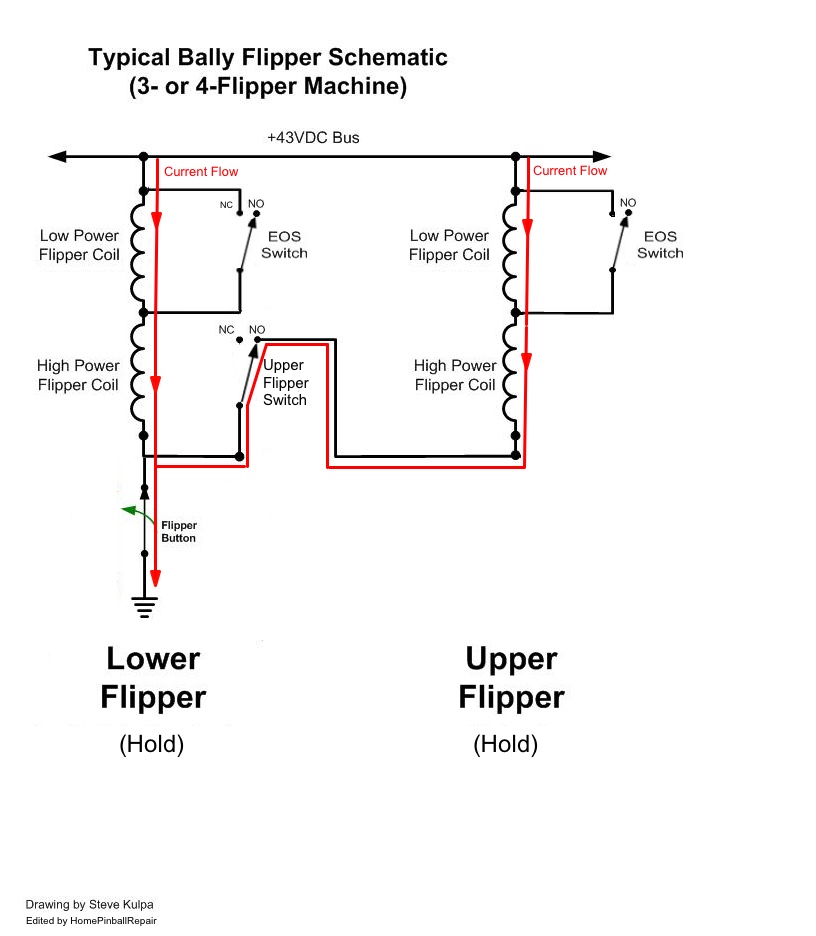
3- and 4-Flipper Machines
Some Bally machines, like Power Play, Eight Bally Deluxe and Flash Gordon, have “upper” flippers. The lower flippers pretty much behave as above, but things change just a little bit for the upper flippers. The upper flippers have their own EOS switches, which perform the same function as the EOS switch on the lower flippers. The difference is in how the upper flippers are powered.
On Bally and Stern machines with upper flippers, there are two switches on the lower flipper: the regular EOS Switch and a second switch that turns on the upper switch when it closes.
These are two separate switches. The EOS Switch is normally closed (NC), while the switch that powers the upper flipper is normally open (NO).
When the flipper button is pressed, the lower flipper goes first because the path to ground for the upper flipper has not yet been established. When the lower flipper hits its EOS switch, the low power coil is energized as the normally closed (NC) contacts open. This is exactly the same as a two flipper game.
When the two switches are properly adjusted, immediately after the EOS switch NC contacts open, the second NO switch should close. When it closes, the upper flipper coil will have a path to ground and will energize.
By having the two switches operate in this sequence, the power stroke to the lower flipper is turned off as the power stroke to the upper flipper is turned on. This prevents two power strokes on one side from operating simultaneously.
Just as with a single lower flipper, the upper flipper has its own EOS switch, which is normally closed (NC). So only the high power coil is energized and the flipper will flip. Then the upper flipper activates the EOS switch, opens the contacts, and introduces the lower power coil to the circuit. This lowers the total resistance on the upper flipper (just as the EOS switch did for the lower flipper) allowing the player to keep the flipper in the up position.
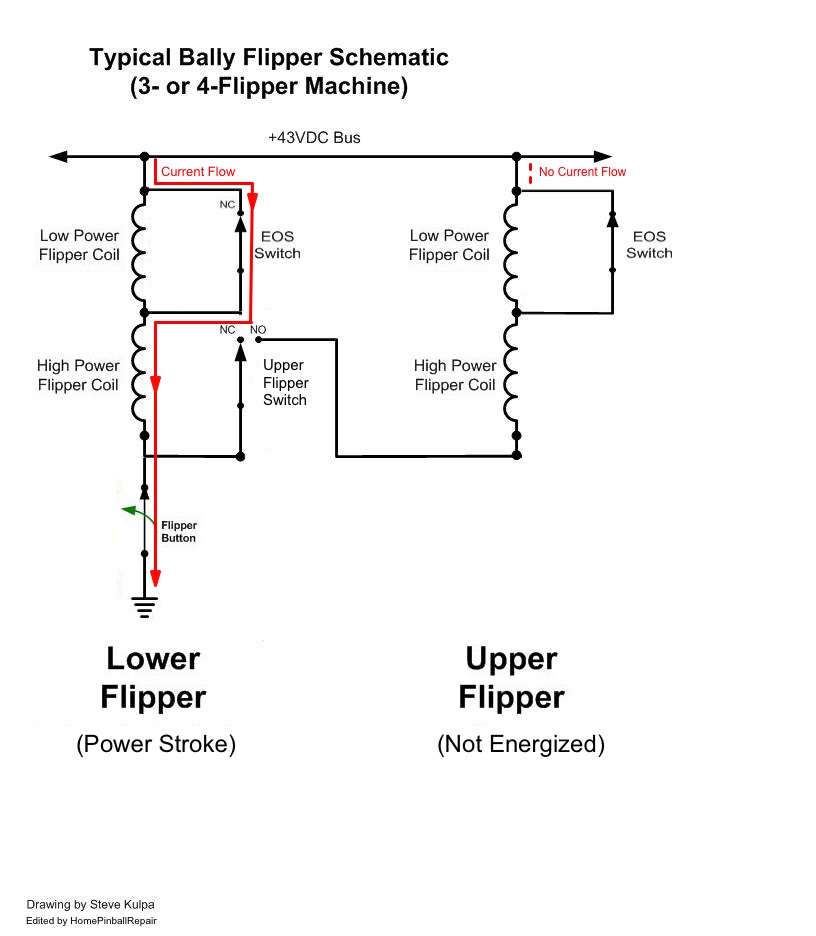
The picture above shows what’s happening just as the flipper button is pushed. This is during the power stroke, that initial high power flip.
Notice the 2 separate switches on the lower flipper, and see how it is not yet supplying a path to ground for the upper flipper. As before, all the current is flowing through the lower flipper’s high powered coil only.
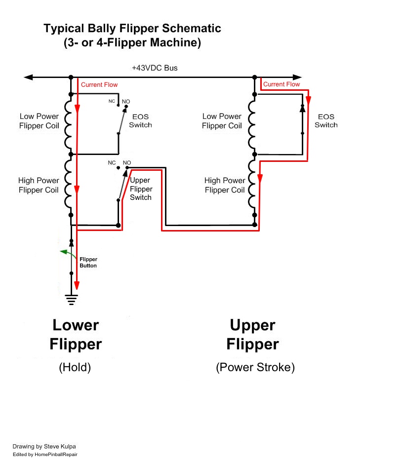
A fraction of a second later, the picture above shows the lower flipper’s EOS has opened which will switch in the lower flipper’s low power coil, allowing the player to hold the flipper in the up position.
At the same time the lower flipper’s Normally Open switch will close. When this happens, the upper flipper now has a path to ground and will energize. You can also see how the upper flipper’s EOS switch is closed, which will power the high power coil for a short time.
After another fraction of a second, the picture above shows the upper flipper’s EOS switch opening up, which switches in its lower power coil. Now both flippers are in the up position, and safely too as the lower power coils on both flippers have been switched in. Both flippers can now be held in this position and draw very little power.
Flippers in Early Solid State Machines
[Note: this is not how EM flippers are controlled.]
Flippers are turned on and off following this circuit diagram:
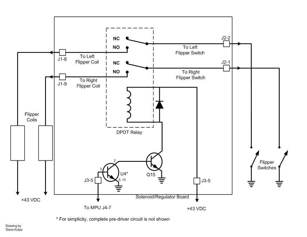
The boxes labeled “Flipper Coils” on the left represent the pictures of the flipper coils and EOS switches from up above [in solid state machines].
The flipper enable relay is located on the Solenoid/Regulator board and is driven by the Q15 driver circuit in early Bally and Stern pinball machines. This is a “continuous solenoid” driver which is controlled by the MPU. When the relay is energized, the two switches inside the relay pull down and complete the circuit from the flipper buttons to the flipper coils. As long as the relay is energized, the flippers will respond to the buttons.
If all of your flippers do not work, you should check the Q15 driver circuit and make sure it’s OK. You can ground the tab on Q15 and that should make the relay pull in. While that DOES NOT test Q15, it does verify the circuit traces from Q15 to the relay are good, and that the relay itself is working properly. If the relay is working properly when you ground the tab of Q15, make sure the flipper relay pulls in during the solenoid diagnostic test. If it does pull in, then Q15 is OK. If not, replace Q15. If the relay is working properly but your flippers are not, then you probably have a problem with the wiring, the flipper switches, or the coils and/or EOS switches.
On a rare occasion, the relay will fail and neither flipper will work. On an even rarer occasion, the switches inside the relay will fail and one or the other (or both) flippers will not work. You can usually hear the relay pull in at the end of the MPU boot process, just around the time you see the 6th flash on the MPU’s LED [in early Bally / Stern SS pinball machines].
Next: Parallel Coils