A. The Tools
B. Cleaning the Contacts
1. Gold Contacts
2. Silver Contacts
3. Tungsten Contacts
C. Leaf Switches
1. The Parts
2. Adjusting
3. Rollover Switches
D. Pop Bumpers
E. Flipper EOS Switches
F. Stationary Targets
G. Microswitches
1. Adjusting
2. Replacing a broken switch wire
H. Opto Switches
1. Slotted Optos
2. Fixing Optos
3. Replacing Optos
4. Replacing Raw Optos
I. Reed or Eddy Switches
The Proper Tools
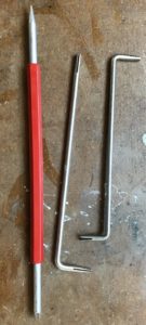
The proper tool to use is a dedicated switch adjustment tool. You can make your own from a section of 3/16″ metal rod – about 7″ long. Then cut a notch with a cutoff wheel from a Dremel. Or purchase one from The Pinball Resource, Marco, Pinball Life, or other pinball parts supplier.
Never use needle nosed pliers. Just do not do it. The angle of the tool seems to result in twisting of switches.
While purchasing this switch adjustment tool, also get a flexstone file.
Other tools required are screwdrivers, isopropyl alcohol (not rubbing), Q-tips, thin cardboard (business cards work). Solder and a soldering iron may be needed if removing or replacing a switch.
Note: Click on most images for a larger photo.
Cleaning the Contacts
Never use a contact cleaner, WD40 on the switches. Many of these liquids are flammable and the sparking of a switch can cause a fire.
Gold Contacts
Prior to adjusting, it is important to clean the contacts. For SS and EM pins with gold contacts, it is easy to clean with a Q-tip and isopropyl alcohol. Isopropyl alcohol is the only exception to the ‘No Liquids’ rule because it quickly evaporates and does not leave a residue.
Caution: Be certain to not use very much isopropyl alcohol and use only in a well ventilated area. Follow precautions on the container.
Sometimes there is dirt that does not come off with the alcohol. In that case, put a thin piece of cardboard between the contacts, push them together and pull the card between the contacts.
Never use a flexstone, file or any other abrasive material on gold plated switches.
Silver Contacts
With EM games, the power to fire a relay travels through the playfield switches. These switches have silver contacts. To clean these switches, use a Dremel 443 brush or a flexstone file. Flexstone files can be ordered from pinball supply houses. 400 grit sandpaper or a small metal file can be used, but the Dremel brush or flexstone is better. We prefer the Dremel 443 brush as it is less destructive.
In addition to the switches located under the playfield and the flipper switches, EM games have switches in the backbox and, usually in the cabinet under the playfield. Dirt or wear on these switches can lead to malfunctioning games.
For EM silver contacts, they can be cleaned with isopropyl alcohol. Then insert a flexstone between the contacts, press them together and move the flexstone back and forth. It is important not to press too hard and bend the leafs as that will cause them to file not parallel to each other.
Tungsten Contacts
The cabinet flipper switches and those at the flipper switches (EOS or end of stroke) handle higher currents, have tungsten contacts and are designed differently*. Worn or dirty flipper and EOS switches will lead to weak or non-functioning flippers. They can be filed with a standard metal file, or they may need to be replaced. A flexstone file used on EOS switches will wear out the flexstone and destroy the file.
* Except those on newer solid state or Fliptronics flipper systems. They use gold contacts.
Leaf Switch
Switch Components and Proper Positioning
 The most common switch in games is the leaf switch. It is used in pop bumpers, roll over lanes, stationary targets, star rollover buttons, sling shots, etc. The key to making them work properly are to clean the contacts and to adjust them the proper distance apart.
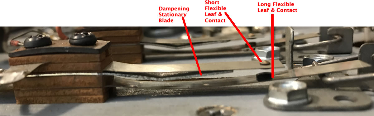
To understand how a leaf switch works, it is necessary to understand the components and what they do. There are two (or more) flexible leaf‘s (also called switch blades). Each of these has a contact. There is usually one or more stationary blades (or dampening blade) that are not flexible.
The longest flexible leaf is the one that moves when the pinball hits. It needs to be positioned against what is moved by the pinball (rubber ring, target, button, pop bumper ring, etc.).
The other shorter flexible leaf is stationary until the moving long leaf hits this short leaf.
The thick stationary blade (dampening blade) holds the short flexible leaf in a fixed position and keeps the short flexible leaf from swinging around or dampens the movement.
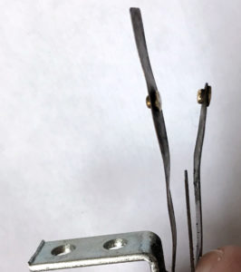
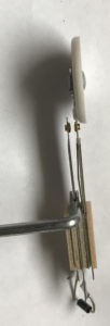
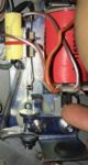
The next picture shows a mangled, improperly adjusted, leaf switch. This sort of twisted switch usually occurs when someone uses the wrong tool and adjusts the switch at the wrong point.
Plus, the shorter leaf should always be adjusted hard against the thick stationary (dampening) blade. Here, the shorter leaf is ‘swinging in the wind’. The purpose of the stationary blade is to hold the second shorter flexible blade in a fixed position. That allows the longer leaf to be positioned as close as possible to the shorter leaf, without the short leaf bouncing around causing false hits.
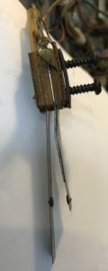
The next picture in this section shows the shorter flexible leaf properly bent against the thick stationary (dampening) blade. Done this way, the shorter leaf will stay in one position, while the longer leaf is moved by the action of the pinball.
This switch is used under a star rollover button. The longer switch acts as the only spring, pushing up the rollover star. The shorter flexible leaf is bent against the thick stationary blade. The thick stationary blade holds the shorter flexible leaf in position.
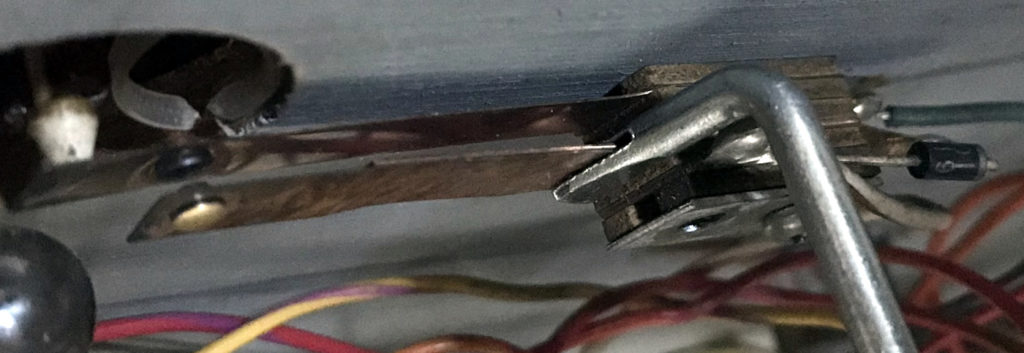
In the next photo, a lane switch is properly adjusted. When the ball rolls through the out lane, the ball pushes a lever down against the switch. The long flexible leaf moves down and hits the short flexible leaf.
Because the short flexible leaf is bent against the heavy stationary blade, the two contacts can be adjusted close together without fear that machine activity will cause enough bouncing for the switch contacts to hit.
Adjusting the Switch Leafs
Generally, the leafs should only be bent with the leaf switch adjusting tool and the bending should only be done near where the ‘sandwich’ is located and held in place by the two screws. The rest of the leaf should remain unbent and straight – no curves or angles.
If there is a thick dampening stationary blade and a flexible leaf together, generally they are bent together.
When the flexible leaf is bent away from the thick stationary blade, it can be difficult to bend only the flexible blade. Try using your tool on the flexible leaf, only.
Here is a star rollover being adjusted for the proper distance from the long flexible leaf. Note that in this application, the long flexible leaf must be bent up as it is the ‘spring’ pushing up the roll over button.

Star roll over switches are particularly difficult to get right. The contacts have to be as close as possible so that a fast roll over by the pinball registers with the game. Using the thick stationary blade properly to set the gap, the two contacts can be quite close together without the switch ‘bouncing’ and causing false points.
Other Rollover Switch Adjustment
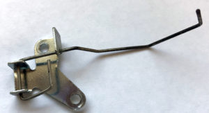
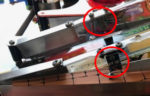
Rollover leaf switches have another component: the part above the playfield. When the pinball moves through a rollover, a small wire lever is pushed downwards against the leaf switch. If this is not adjusted properly, the leafs can be adjusted correctly, but the switch still does not activate.
It is pretty easy to use the switch adjustment tool to bend the wire so that it sticks up further into the playfield. But be careful as some of these are meant to allow the ball to move in either directly. If the wire is bent improperly, the pinball may not be able to move ‘against’ the switch.
Pop Bumpers
The most difficult leaf switch to adjust properly are the pop bumper switches. Too close and the pop bumpers will activate without a pinball hitting it. Too far apart and a the game has a dead pop bumper.
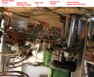
First, clean the contacts. Then, most importantly, loosen the screws holding the switch and move the switch so that point coming down from the skirt is in the center of the ‘spoon’. If it is off center, the pop bumper will work when the ball hits one side of the pop bumper, but not the other. To make this easier to see, darken the end of the skirt point with a black sharpie.
Then adjust the switch in the same manner as the rollover switch.
Note that sometimes the plastic ‘spoon’ gets worn and should be replaced.
Flipper EOS Switches
The flipper EOS switch is a leaf switch just like those above. Adjustment is similar.
[Click on the image for a larger picture.]
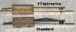


The first photo is a comparison to the Williams Fliptronics EOS switch to a standard EOS switch. Note that the contacts are not touching when at rest. This is known as ‘Normally Open’ or NO switch. The second switch is a standard EOS switch used by all standard flippers (non-computerized).
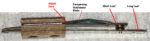
The second photo identifies the parts in the EOS switch. These are similar to the leaf switches used elsewhere in a pinball machine. The leafs should be adjusted so that the dampening stationary blade and short leaf are pushing against each other. The dampening blade holds the short leaf in position and keeps it from ‘swinging in the wind’.
The long leaf should be pushing firmly against the short leaf. There should be no situations where action during game play can cause these contacts to separate. The third photo shows the contacts make full contact while ‘at rest’.
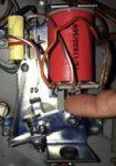
When testing for the gap, it is better to push in on the plunger, rather than grab the flipper bat or the linkage. That is because, even with new flipper parts, there is a little bit of play in the linkage. Pushing the plunger into the coil will show the gap when the coil is activated.
The forth photo shows the plunger being pushed fully into the coil and the EOS switch gap. Note that the two contacts are apart, but not too far apart. If the contacts are further apart, then the switch opens too soon, which reduces power. If they are too close together, arcing can occur.
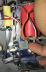
When releasing the plunger, hold it so that the two contacts are just touching (photo 5). Then observe what happens when you let go: the longer leaf should push back the shorter leaf just a little, insuring proper contact (photo 6).
Photo 7 shows the gap using a micrometer. This is overkill, but we did it just to show the size of the gap in the photo.
If adjustment is necessary, the dampening stationary blade and short leaf should be bent at their base. That will increase or decrease the gap when the flipper is activated. After adjusting, insure that the two blades are still pushing against each other.
For additional information, see the section on Rebuilding Flippers.
Stationary Targets


Stationary targets are another type of leaf switch. This one has two flexible leafs and two stationary blades. It is important that the flexible leafs be against the stationary blades to hold everything from bouncing.
Sometimes we find it easiest to adjust these switches by removing them from the playfield. But, on occasion, they are adjusted perfectly, but when reinserted into the playfield, the hole pushes the target back and causes the switch to be stuck closed.
Microswitches
Newer pinball machines have done away with most open leaf switches. These microswitches stay clean and are more reliable. However, they cannot easily be repaired or cleaned.
When they do not work, it is usually because the wire above the playfield is bent. That can be adjusted just like in the rollover switch (above).
If a microswitch does not work, it generally should be replaced (or maybe not – see note below).
When activating a microswitch, listen for a faint ‘click’. If not there, the microswitch might be broken. But the only certain test is to use a DVM and check resistance.
As with all non-working switches, a broken wire or open diode can also cause a failed switch and should be checked.
When ordering a new switch, sometimes it is possible to order the ‘naked’ switch and move the old switch attachment to the new one.
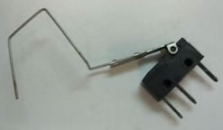
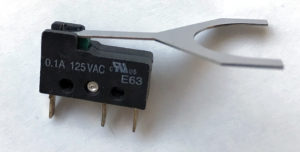
Here are two different micro switches. Both can be adjusted by bending the wire or tab coming off the switch with a switch adjusting tool.
The smaller of these two switches are commonly used in Stern ball troughs. Both of these switches are usually in a switch matrix and needs to have a diode installed.
Note: Michel_K17 has come up with a way of ‘fixing’ these switches that is an option, instead of replacing. This is great for those of us that just hate throwing stuff out. We have tried this fix, and it worked, for a while.
Replacing the Wire on a Microswitch

If the wire breaks on a microswitch, generally, you are out of luck. Getting a wire to work on a microswitch seems to involve some spot welding of sorts.
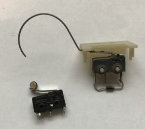
But there are older microswitches on ~80’s games, that are much larger than modern microswitches where it is possible to replace that wire.
The trick is getting 0.024″ (or perhaps 0.026″) piano wire from a music shop. Pry off the retainer washer holding the broken wire on.

Cut a new piece of piano wire. Bend a ‘U’ at the end of the wire and position it in the slot of the switch. Just for fun, we put a tiny spot of UV activated glue into the slot with the wire.
Press back on the retaining washer. Bend the wire with needle nosed pliers.
Diagnosing Problems with a Microswitch
If having problems with a microswitch, diagnosis of the issue is pretty straightforward:
* Locate the switch matrix in the service manual and find the switch number and the column / row in the matrix.
* Turn the game on to reset any drop targets. Turn the game off.
* Remove the pinballs and lift or slide out the playfield.
* Locate the microswitch.
* Turn the game back on and enter the service menu then the switch test. On DMD games, there should be a graphical matrix. With non-DMD games, there may just be a switch display number.

* Push the switch down and listen for the click. Make sure the switch lever is not bent so that the switch cannot open all the way. If no click, you can try cleaning the switch, but, generally, it will have to be replaced.
* If the switch clicks, but does not register, the switch could be broken. Or the diode could be open. Or a wire is broken. To test:
– Take a clip lead and connect it to the end of the diode that has the band. This side of the diode will not have a wire connected to it.
– Connect the other end to the tab that does not have a diode, but does have a wire connected to it.
– If the switch closes in the test menu, the switch is defective. If it does not, there is a problem with the switch matrix or the diode is open – test the diode. If multiple switches activate, then the diode is shorted, or you have connected the clip lead to the wrong side of the diode, or there is a problem with the switch matrix.
* If the switch is locked on, it maybe broken and require replacement. Or the wires could be shorted. Or there maybe a problem with the switch matrix.
Opto Switches
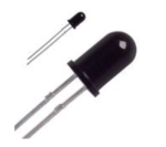
Opto switches are switches are ‘electric eyes’ that use LEDs instead of a physical connection. In theory, they are more reliable. Unfortunately, they burn out and get dirty.
If an opto is not working, or if it is flaky and unreliable, it could be because it is dirty. Clean it with a Q-tip and isopropyl alcohol.
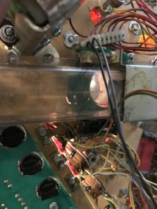
Most of the time, optos stop working because the transmitter (light source) burns out in a 20+ year old pinball machine. The optos used in Williams pinball machines are IR and not visible by the naked eye. However, it is possible to see if the transmitter is working if a camera can be aimed directly into the transmitter – not off to the side. Note: Some cell phone cameras can ‘see’ this IR light but others may not.
Data East/Sega/Stern pinball machines use optos that are visible to the naked eye.
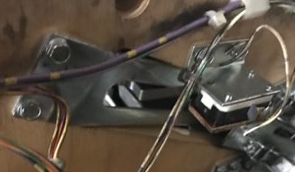
Some Williams pinball machines use optos in the cabinet flipper switches. These can be cleaned for reliability.
These flipper opto switches can be replaced with leaf switches used in Williams Fliptronics games.
If replacing the opto assemblies, it is suggested to replace both the transmitter and receiver to insure that they are both on the same wavelength. It is also possible to purchase the raw LED from Great Plains Electronics (which, sadly, has been shut down), unsolder the burned out LED and solder in a new one (see below).
Note that the type of opto to use depends on the game. Bally / Williams WPC used QED123 for the transmitter and QSD124 for the receiver. DE/Sega/Stern used different raw optos and these are usually listed in the manual. These raw optos maybe purchased from Pinball Life, Marco, or electronics supply stores such as Newark.com, Mouser, or Digikey, sometimes for less than $1 each (plus shipping of course). We purchase ~100 at a time and replace every opto transmitter and receiver when we overhaul a 30 year old game.
Alignment may be an issue with optos. Sometimes it may be necessary to loosen the screws holding the optos and move them slightly to get optos to work.

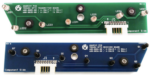
Optos are usually plugged into separate opto boards usually located under the playfield. The opto board supplies power to the transmitter and converts the information from the receiver for use by the computer in the switch matrix.
The picture shows a glowing IR opto transmitter as seen through a camera that is sensitive to IR. Most iPhones cannot ‘see’ IR light.
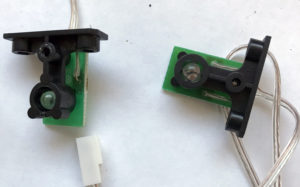
Slotted Optos

‘U’ shaped opto housing are used in many specialty situations. These can include drop targets, the infamous Twilight Zone clock, as well as game specific mechanisms.
They are especially hard to clean because of the narrow slot, but usually a Q-tip with isopropyl alcohol can be squeezed in there. But usually, there is not an option other than to replace the board. The LED within the housing cannot be replaced. It maybe possible to obtain the LED/transmitter housing and replace that part on the board.
Note that some of these boards contain other components that may fail. Any transistors are especially suspect. Resistors are unlikely to fail.
Fixing Non-working Optos
For most optos, there are two components that need to be working: 1) the transmitter and receiver, and 2) the opto board.
For the purposes here, we are going to focus on repair and replacement of the raw opto transmitter and receiver used in Williams / Bally WPC machines. The boards can be replaced, instead.


Replacing Optos
In most cases, it is wise to replace 20+ year old optos, even if they appear to be working. We recently completed a playfield replacement for a Williams WPC Indiana Jones. Since we had everything apart, we decided to replace all of the optos.
When replacing the optos, there are three options: 1) Replace the raw opto, 2) Replace the circuit board that holds the opto, or 3) replace the housing, circuit board and opto.
Option #1 is the least expensive. Raw optos, which are LEDs, are cheap. There are only two leads that must be unsoldered to remove it. The only trick is that they must be oriented in the proper direction (see photos below). For example, the Williams 6 or 7 ball trough opto boards are roughly $100.00. But the individual components (QED123 for the transmitter, and QSD124 for the receiver on most WPC pins) are only $0.65 – $1.00 or so each. So the transmitters and receivers can all be replaced for less than $12.00. And, if you are really feeling lucky, try replacing just the transmitters for $6.00 or less.
Not all raw optos are readily available, so you may have to do a little searching to come up with those that are more difficult to find.
We went the small circuit board route. At $2.25 each or $4.00 for a pair, that is a small penalty vs. the $0.40 x 2 for the raw components. But we saved the old boards and installed new raw LEDs in them for parts.
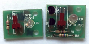
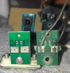
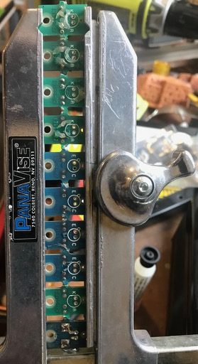
It is crucial to insure that the same wire is connected to the same position (see ‘Positioning to Move Wires’, above). We remove the old board, install the new one, then solder the wires one at a time to check that they are soldered to the right place. The transmitter have pads clearly marked ‘K’ and ‘A’, while the receiver has pads marked ‘E’ and ‘C’.
We usually clip off the old end of the wire, strip a new short part of the wire, tin the wire and the pad on the opto, then put them together and heat.
Replacing the Raw Optos

Replacing the raw optos, the LED and photo transistor located on each board is easy.
The leads are close together, so just touch both at the same time with a hot soldering iron and lift out the old opto. Then clean out the holes, usually with a solder sucker, until the holes are completely clear.

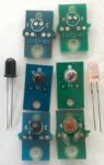
Insert the new ones (see the photos for the correct orientation), solder and then clip off the leads. All done.
Note that the darker opto is the photo transistor – the receiver. This is the Williams WPC opto receiver board and a replacement is QSD124, a NPN Infrared Phototransistor. In the original board, there is a drawing of a ‘tab’. The raw transistor we received do not have a tab. Instead, it has a flat side. The flat side is the shorter ‘E’ lead which should be positioned towards the ‘tab’ on the board. As far as we can tell, all QSD124 photo transistors have the same lead orientation.
As of early 2022, Pinball Life sells a similar replacement photo transistor, but the lead orientation is the opposite of the QSD124 (Pinball Life said they were going to discontinue this specific part). And both leads are the same length. This may change. Marco responded that they did not have a Datasheet to determine lead orientation.
The lighter color is the transmitter QED123 infrared LED used in the Williams WPC optos. It has a flat side. The flat side matches up with the board flat side drawing. The shorter lead, ‘K’ (cathode), goes into the left hand hole.
Note: It is crucial that the new opto & receiver be installed perfectly flat to the board, or they may not align. Since this can take three hands, we usually solder one lead. Then we go back and reheat that one lead while pushing the LED flat against the board, holding it there until the solder cools.
This is the same procedure for ball trough opto boards, except that there are several transmitters on one board, and the same number of receivers on the other. While it is the best idea to replace both the transmitters and receivers, we frequently try to cheat and just replace the transmitters. If that does not work, then go back and replace the receivers.

Note that other games, such as DE/Sega/Stern use different optos and their leads might be different orientation, especially for the photo transistor. For example, some Stern, Sega and DE optos are MV8114 (equivalent to MT5000UR and TLRH180P) which is used for both the transmitter and receiver. This part is obsolete and getting harder to find.
There is a service bulletin on the operation of the DE/Sega/Stern optos. Replacing the raw optos is the same procedure as replacing those in WPC pins, except that the transmitter and receiver are the same MV8114 part.
Some games use ‘slotted’ optos. Those have the transmitter and receiver in the same housing and must be replaced together. The slotted optos used in some WPC games (the QVE11233.0086) have different dimensions and higher current capabilities and maybe difficult to find. However, DE/Sega/Stern slotted optos can be relatively easy to find. These are also used on some Williams boards.

If the correct part can be located, replacement is fairly easy and far cheaper than a new board. Note that four leads will have to be unsoldered and, once again, correct orientation is crucial. And it must be installed perfectly flat against the board.
For those wanting detailed technical information on the Williams slotted optos (notably used in the Twilight Zone clock), please see this excellent thread.
Reed or Eddy Switch
A few games use a reed or eddy switch. It is a box that is magnetic and senses the iron in a pinball. They are completely sealed. Other than checking the wiring and plug, there is nothing that can be done to clean or repair these switches. These switches are becoming difficult to find, and can be expensive when available.
External Links
How to configure opto switches
What is a Phototransistor
Introduction to Phototransistors
Comments
Comments, including suggestions, improvements, errors, etc. are welcome (see below).
If you have a specific question about your game that does not directly apply to adjusting switches, please see our FAQ section.
Can switches, like leaf switches, be salvaged from older em machines to replace switches from a machine from another decade? I have a 1970’s gottlieb em. I bought a back box from a 1950’s era Bally on a whim. I wanted to frame the backglass. All the switches are still in the older back box., I was thinking of keeping some of the switches if they can be used again.
Absolutely those switches can be reused. People do that all the time.
We are restoring a 1957 Williams Baseball game. One of the leafs on a relay are broken off and going into our supply of old switches, we should be able to replace it.
But care needs to be taken to use the same type of switch. Higher current replacement leafs, usually made of tungsten, must be replaced with tungsten, and silver with silver, etc.
If you have the room, keep as many as possible. And please do not throw any out. Sell any ones you do not want to help keep these old machines alive.
I’m curious if you know where I could find a leaf adjustment tool like the red one in the photo. I have one that I love but I fear it getting lost and want to have another.
We wish we knew. That red tool is our favorite as it is more durable than the other styles. We have had it for decades and think that we inherited it from a late father or father-in-law of one of the group.
We suspect that it was a ‘make it yourself’ tool. We think it was a un-slotted tool and the slot was cut, perhaps using a type of band saw with a thin blade.
That switch adjustment tool is highly valued.
I took a pic of this tool that is from an old man’s soldering kit. It has a name melted into it. “HYCON ENG 33”. Im just saying that it is specific to being a tool of some e repair tradesperson and not a mod on to a random implement. I learned a thing or two by your articles,thank you.
The odd connection is photo-google lens. Your pic pulled out of the massive, cavernous data acreage of these interwebs.
strowger or neuses switch adjusting tools?
We are not sure we understand your question. The switch adjusting tools available at Marco, Pinball Life, Pinball Resource all work fine. It is also possible to make your own switch adjusting tool, but it requires a careful cut to create the slot. That likely requires a band saw. We hope this helps.
The red tool comes from an old Weller soldering gun kit
I have the same tool
It was not made for adjusting switches but works great !
Thank you Michael! The mystery is solved. 🥳
I made a few of these with a Dremel cut off wheel..Allen wrenches work well for tool stock.
The poster is referring to the switch adjustment tools. He makes his own, using the Dremel auto off wheel.
Thanks Jerry for the post.
https://www.marcospecialties.com/pinball-parts/77-SWK
Do leaf switches just give out sometimes.
One of the rollover lane leafs stopped working on my ’79 Williams Flash machine.
It appears it is still making contact, but not scoring or lighting up.
“..give out..”. We are shaking our heads on that one, not quite knowing how to answer.
High power contacts are tungsten. They can arc and may need to be filed or replaced. EOS and flipper button switches are examples. EOS switches especially ‘give out’ and need replacing.
Low power leaf switches, like your rollover leaf, are gold contacts. If someone has filed them, then they are ruined. But otherwise, they last a very long time.
And these contact point / tabs at the end of the leaf switches sometimes fall out. Or get loose. If they get loose, we have had luck with soldering the backside of the switch and contact point together. And with some switches, the tab where the wire solders to the switch is a separate piece from the leaf. We have thought that it is possible that some oxidation (tarnish) might occur between the two.
Plus the leafs can be so badly mangled that they might not ‘spring’ properly. Or the two might not contact each other correctly – the contact points should be flat to each other.
But given that the leaf switches are purely mechanical, the cause of failure should be able to be seen.
We usually start by turning off the pinball machine, setting the voltmeter to resistance (lowest setting if not auto ranging), connect it to the tabs, then close the switch and read the resistance. If it is not near zero, then there is an issue to find with that switch. But if the resistance is near zero, the problem is not with the switch.
We had some switches on a Williams Firepower that seemed to require constant maintenance. We tried everything. We finally replaced the switch matrix plugs and pins, and the problems went away. But if yours is just one switch, then this is not the issue. It could be a bad solder connection and it might be at the previous switch in the chain. Or the strands in the wire might be broken, usually at the solder point. Check your switch matrix and look at the wires and solder at the other switches in the same column and row.
great website! Once I get my 1977 Pinball by Stern running again, I’ll replace the displays (only 3 work).
I haven’t found anything about the initial ball eject to put the ball to the shooter. My machine makes the noise that it wants to push the ball to the shooter, but it doesn’t move the ball. Any suggestions?
Thank you,
A good suggestion to add to the website.
At the front of the playfield, near the shooter, is what we call an apron. If you remove the playfield glass and set it aside carefully (it should be safety glass and can explode at the slightest chip), then lift the playfield up just a little. You will see that there are two screws holding on the apron in place.
We put a small 2×4 between the playfield and the cabinet to keep it from falling back down while we remove those two screws.
Then push the apron towards the back of the playfield. Be a bit careful about this as you don’t want to scratch the playfield. It likely will need a few taps or wiggle to break it loose.
The apron will slide forward and lift off. Note how the apron is held in place as it slides off. There are two small pieces of metal on the playfield and the tabs of the apron slide into place. It can be a pain to get both of those tabs in place while sliding the apron back to be held by the screws.
Once you get he apron off, you will see the mechanism – a solenoid with a plunger attached to a metal piece that pushes the pinball + a spring.
You will need to identify why it is not working. You may need to rebuild the solenoid by taking it apart, cleaning and replace the coil sleeve – if the sleeve is damaged.
If the plunger and ‘pusher’ or spring are damaged, they will need to be replaced.
Also, there is a ramp that the ball needs to get up and over. If that is dirty or blocked, that is an easy fix.
We need to add this info and include pictures. So much to do….
I have a 1981 Bally Embryon pinball machine. It was working fine up until a month ago when I caught my nephew playing it and he was pushing the start button repeatedly during the game to try to give him extra plays. Needless to say it damaged the machine and now the switch that detects the ball in the channel at the base of the playfield that activates the solenoid to send the ball to shooter channel is not working. Is it the switch that is not working or could it be something else on the main board. I have a spare playfield with many of the switches, solenoids and diodes that I could swap out if necessary. I’m not sure how I should troubleshoot this.
Thank you
While we don’t condone pressing the start button repeatedly, the only issue that should cause is a premature wearing out of the button. We cannot imagine it damaging the machine – so that seems to be a coincidence and your nephew is innocent of causing that ‘damage’.
It sounds like you have not installed the free play second button, assuming you have the original boards from Bally.
https://homepinballrepair.com/set-early-bally-stern-williams-pinball-to-free-play/
” Is it the switch that is not working or could it be something else on the main board.”
The best way to test this is to go into the service menu. You will need the user manual to do this. Prior to doing so, remove the pinball and make sure any targets or switches are not closed.
Go into the switch test and see what switches are closed. None should be if you have removed the pinball and reset everything. Bally shows only one switch at a time, so if there is a number displaying, use the manual to determine which switch is closed and open it. Repeat this until no switches are closed. Then put the pinball in the ‘out hole’ that leads to the trough and see if the switch closes. If it does close, then the switch and circuits are not at fault. If it does not close, then insure that the leafs make contact (see switch adjustment pages). If they are making contact, then check the other switches in that row and column to insure that you don’t have a wiring or board problem. Then consult the troubleshooting switch matrix page.
If the switch closes, then go into the solenoid test and see if that solenoid fires. If it does not, then you will need to troubleshoot the solenoid – see that section of our website.
Please let us know what happens.
does anyone know the name of the leaf switch (Rock Ola Jukebox) that has a split (two) two small pieces of metal at top of switch area for individual wire solder to each one. all I can find is one large top of switch . Can’t find it anywhere….
Joel Scherer
j3343@comcast.net