Fixing Sega and early Stern Flippers – Whitestar
B. How Flippers Work
An overview of how all flippers work.
C. Initial Troubleshooting
D. The Circuit
E. Fixing
F. Contact Information / Feedback
G. External Links
Initial Troubleshooting

1) One flipper stays stuck up when the power is turned off:
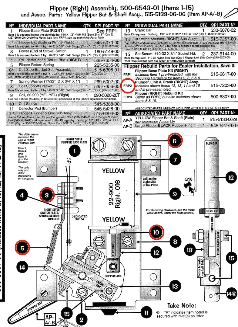
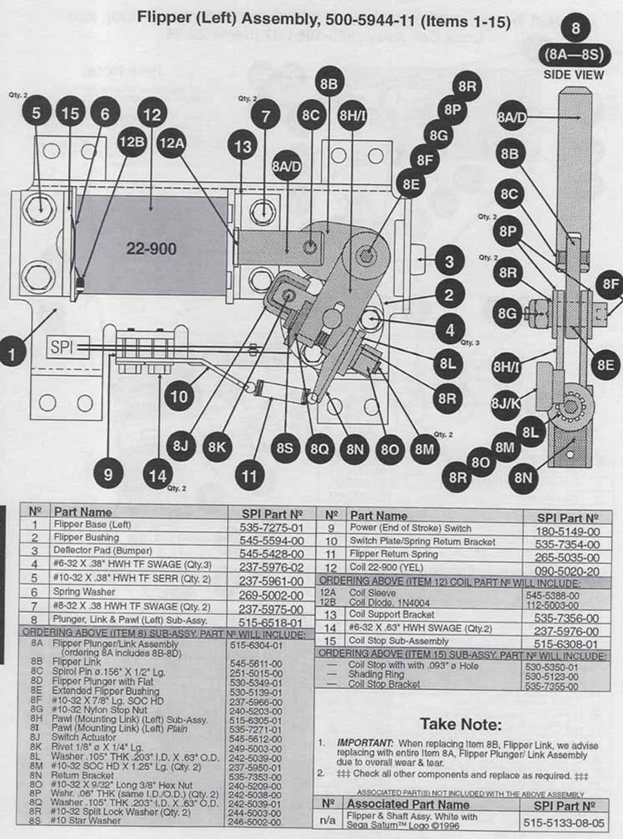
This is a mechanical issue. By hand with the power off, move the flipper up and down. If you detect anything other than a smooth movement, it is time to rebuild the flippers. This can be a mushroomed coil stop, burs on the plunger, damaged coil sleeve, and more. If this happens to one flipper, then the others are close to needing a rebuild too, so just do them all.
2) Loss of power in one flipper:
This is usually mechanical. In these computer controlled flippers, it cannot be the EOS switch.
Don’t replace the coil unless it shows signs of having been overheated. A melted coil will bind up with the plunger.
Coils don’t wear out. Check the resistance vs. the other coil if concerned about damage.
3) Both flippers do not work:
Check the fuse(s) for the flippers. The main flipper fuse is located on the PPB board and, in most cases, is F5, but check the schematic for your specific game.
4) One flipper does not work at all. The other one does.
Check the fuse under the playfield. Each flipper has its own fuse. This could also be a broken wire, bad flipper button switch, etc. The EOS switch cannot cause this problem. There is not a fuse on the power supply for the flippers. If F6 on the power supply is blown, none of the high power solenoids, including both flippers, will work either.
5) One flipper stays up when the power is turned on.
This is usually a blown transistor (FET). On many of the games, these are Q15 and Q16. IRL540 is the replacement. See the Coil Detailed Chart Table in the manual for confirmation.
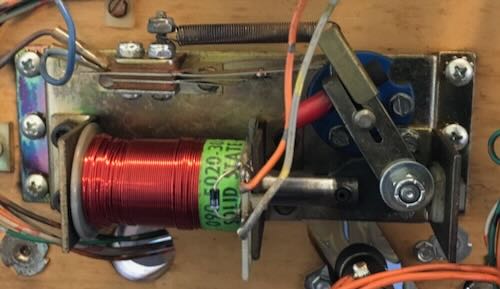
When this FET blows, it is frequently because the diode on the flipper coil is broken. Take a small screwdriver and gently try to pry it away from the coil to see if it is broken. Replace with a 1N4007 (best) or 1N4004 (good) with the mark on the diode on the same tab on the coil.
Only after checking and replacing this diode (if needed) should you replace the FET for this flipper.
Sega / Stern Solid State Flippers – Whitestar

In the mid-1990’s, Sega introduced a new CPU board system called Whitestar. When Stern purchased Sega, they continued production with the Whitestar system for several more games.
The first two, Apollo 13 and Goldeneye used a separate flipper board located in the cabinet like the DE/Sega games did. To troubleshoot flippers in these games, see the DE / Sega flipper troubleshooting page.
From Twister on, the flippers were controlled by the power driver board FETs and the CPU.
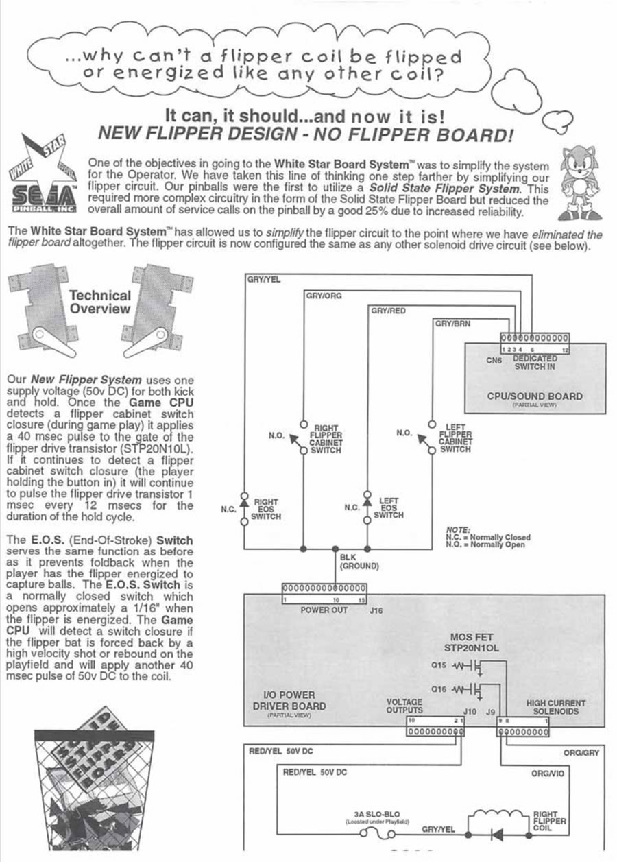
While the DE / Sega system had a 50 VDC and a 8 VDC power supply, the Whitestar system makes use of only one power supply, 50 VDC. The power stroke is a 40 msec pulse like it was on the DE/Sega board; but the hold circuit is now also 50 VDC, but just for 1 msec every 12 msec. This short burst of full power mimics the hold of an 8 VDC power supply because it is a very short duration. The 50 VDC is generated in the power driver board and is also used for the other coils, but the flippers have their own fuses. One fuse is on the power driver board and goes to both flipper coils. The other two fuses are located near the flippers. Note that there may be some variation of this setup from game to game.

The EOS switch plays the same role as before: it detects if the flipper is being pushed too much and tells the computer to increase the power. The flipper can operate normally with a defective EOS switch.
According to Sega / Stern: The EOS switch should be adjusted so that it opens 1/16″ when the flipper is open. During this period of time, the computer applies the short pulse of 1 msec ever 12 msec. If the flipper is pushed down, so that the EOS switch closes, the computer then applies 50VDC for 40 msec. If the EOS switch is missing or misadjusted, then the flipper could be forced closed while trapping pinball(s) with the flipper.
The flipper switches are dedicated switches to the CPU coming in on CN6. Closing the flipper switch grounds the connection to the CPU.
Stern Flipper Software Upgrade
Note that later Whitestar games, such as Lord of the Rings, had a software update allowing the operator to change the strength of the flippers by modifying the timing of the power stroke. These are Standard Adjustments 53, 54, 55. Stern partially explained the purpose of these adjustments, so we did our best to interpret them.
“Flippers will now fire when the button is pushed until the End-of-Stroke (EOS) Switch closure is seen. When EOS is seen, continue firing for the amount of time in Std. Adj. 55. When this time is expired, if the minimum time has not yet been met (Std. Adj. 53), then keep firing until it has. Otherwise switch to hold power. • If the flipper has been firing and it reaches the maximum (Std. Adj. 54), then switch to hold power. • If the flipper caves-in (EOS re-closes) while the button is still held, then refire the flipper at full power. Switch to hold power as soon as EOS is seen, no minimum times are enforced in this situation. • If the flipper caves in several times on the same single flipper button press, then stop refiring at full power and just stay at hold. • If the flipper fails to open the EOS switch several times, then assume it isn’t working and fall back to a “safe” fire time so as not to burn up the coil. Three (3) new STANDARD ADJUSTMENTS were added to control the flippers.“
To us, it seems as if the EOS switch now plays a much greater role than it used to, which it just detected the flipper being forced closed.
 “53 FLIPPER ADJ 1: Set between 05 to 40. Default is 10.
This adjustment sets the minimum fire time for a flipper coil in milliseconds.“
“When this time [Adj 55] is expired, if the minimum time has not yet been met (Std. Adj. 53), then keep firing until it has.” This appears to us to set a minimum time to fire the coil at full power, when the switch closure occurs. Oddly, if Adj 55 is set to zero or any value less than Adj 53, wouldn’t Adj 53 always control?
“54 FLIPPER ADJ 2: Set between 40 to 60. Default is 50.
This adjustment sets the maximum fire time for a flipper coil in milliseconds.“
This allows the operator to adjust how long the power stroke is applied, no matter when the EOS switch opens. Interestingly, the default is 50 msec when it used to be 40. This is especially beneficial if the EOS switch breaks.
“55 FLIPPER ADJ 3: Set between 0 to 10. Default is 3.
This adjustment sets the amount of time to fire the coil after the EOS switch is seen in milliseconds.“
“Flippers will now fire when the button is pushed until the End-of-Stroke (EOS) Switch closure is seen” is confusing. If this were to mean closing, then this seems to us to apply if the flipper is forced closed due to a force such as trapping a pinball. The amount used to be 3 msec, which is the default here.
The Sega/ Stern Whitestar Flipper Circuit

This is the simplest circuitry of them all – it works like any of the other coils on the game. The 8A TIP102 (or TIP120) are no longer used. Instead, a more robust 100V 20A MOSFET STP 20N10L is in its place. IRL540 is a direct substitute.
To fire the flipper, data is sent over from the CPU which tells IC U2 to turn on. The signal comes out to the FET transistor controlling the flipper. The FET turns on, completing the circuit to ground.

Note that there is not a snubber diode on the I/O board. If the diode on the coil is broken or open, the FET is likely to blow. The transistor (FET) used to activate the flipper coil may vary from machine to machine, so it is important to look at the coil chart table to identify which transistor is used.
Troubleshooting Sega/Stern Whitestar Flippers

If both flippers do not work, check the fuse located on the power driver board. Check your manual for the correct value of the fuse.
If one flipper does not work, check the fuse to that flipper. The fuse should be located underneath the playfield in the vicinity of the flipper.
Check for voltage present at the I/O Power Driver Board. LED L201 should be lit. The voltage can be checked at F20 or F21 – note that these fuses are not in the flipper circuit. The voltage can be checked at the coil also (unlike the DE/Sega flippers).
If the flipper still does not operate, it is possible to check the circuit the same way that coils are tested in older WPC pins: briefly short the tab of the FET to ground. The flipper should activate. If it does, it is likely that the FET (MOSFET) has failed. Replace it with an IRL540. Important: do not use a TIP 120/102 transistor.
If the flipper activates (locks on) when the game is started, then the FET is likely shorted. Replace it with an IRL540.
If the FET has failed, be sure to inspect the diode on the coil. If the diode is broken, missing or open, then the FET will blow again.
Comments
Comments, including suggestions, improvements, errors, etc. are welcome (see below).
If you have a specific question about your game that does not directly apply to solid state flippers, please see our FAQ section.
External Links
DE/Sega/Stern History
Optos and Weak Flippers
Copyright 2006 – 2025, all rights reserved.