Caution
A. Caution
B. Parts Needed
C. Getting Started
D. Understanding the Symbols
E. Other Symbols
E. The IC
F. Decoder IC
G. Using the Probe
H. Early Bally Troubleshooting
– Lamp Board
– Solenoids Board
I. Gottlieb System 1
– Solenoids
J. Williams System 11
– Solenoids
– Williams 3-7 & DE
K. WPC
L. Switch Matrix
– the Switch Matrix
– WPC switch matrix
– Early Bally/Stern
Pinball machines contain potentially lethal voltage. Dangerous voltage may remain for a period even after it is unplugged. Prior to opening a pinball machine, be certain to unplug it, then turn it on to insure that it was actually unplugged. It is recommended that the machine be allowed to sit several minutes to allow any remaining power to dissipate. High voltages can be present on any machine, even unplugged, and it can be lethal.
In order to use a digital logic probe, the pinball machine must be turned on and operating. There could be voltages nearby to run plasma / DMD displays that could run several hundred volts. These voltages could be deadly.
Repair should be left to properly trained personnel. If you are not qualified, you should not work on a pinball machine.
Solvents such as isopropyl alcohol and WD40 are flammable and should be used only in a well ventilated area. Do not operate the pinball machine until the vapor has dissipated. A spark in a machine can cause a fire. Follow all the warnings on the container. Never use WD40 on a pinball machine.
Proceed at your own risk!
It is with some trepidation that we write this section. Prior to proceeding, ask your self the following questions:
1) Am I good with electronics and am I qualified to work around high voltages.
2) When I find the problem, can I remove the circuit board, remove the defective part and solder in a new component?
If the answer to either of these two is not a resounding “YES”, then find someone else to work on your pin. They may look like something one can tackle, but they are amazingly complicated machines.
Parts Needed

Anyone planning on troubleshooting a pinball machine will eventually need a digital logic probe, or wish they had one. If you are planning on doing your own electronics work, buy one now, not when you need one. They are inexpensive, but generally no longer available at your local electronics store. There is no reason to get a fancy probe. A simple one will do. We prefer a probe that makes an audible tone, so look for that.
[Note: Click on most images for a larger photo.]
Required:
- DVM – everyone must have a voltmeter to go with the probe
- Clip leads – they come in handy to make connections.
- Digital logic probe – the one we use is from Radio Shack. Sadly, they no longer sell it. Here are options but we have not tried them:
Amazon sells an inexpensive logic probe, the Elenco Electronics LP-560 Logic Probe. It appears to do what is needed. They also sell a BK Precision DP Series Digital Logic Probe that is more expensive and appears to be better built.
Jameco has a nice one, Part no. 149930. It seems a bit expensive, but will do.
Getting Started
The first step is to read the instructions that come with the digital probe. Yours may vary, but these are mine:
- Never connect the probe to a voltage more than 15 V (see your probe for specs).
- Do not touch the probe tip while using the probe – static electricity can fry this thing.
- Always connect the probe to the power source and ground prior to testing the circuit
- Remove the probe from the circuit prior to disconnecting the power source
- Connect the black wire to ground. We prefer the central ground to the pinball machine like the driver board or power supply.
- Connect the power source to the red (+) lead. It will be +5 VDC or +12 VDC depending on the circuit. More on that later.
- It is a good idea to use the same power source as is connected to the board under test.
If used to reading circuits or you really don’t want to know the geeky stuff, skip to “Using the Probe“, below.
Helpful Stuff You Don’t Have to Know
Understanding the Symbols
 There are many different symbols used in digital circuits. The good news is that you do not need to understand the differences in order to understand what is going on.
[Note: On most photos, click for a larger image.]
Buffer – + goes in, + comes out. Acts to isolate the input.
NOT – inverts the output. + in and – out.
AND – Both inputs have to go + for the output to go +.
OR – Either or both inputs goes + for the output to go +.
NAND – Same as AND, except the output inverts. Both inputs go +, the output goes -.
NOR – Same as OR, except the out inverts. Either input goes +, the output goes -.
XOR – Almost like an OR, in that if either input goes +, the output goes +. Except if both go +, the output goes -.
XNOR – Inverts the output of XOR.
Gates
Above are many of the different logic gate symbols that you might see in a circuit. For the most part, they can all be thought of as a buffer. The signal comes in and it goes out.

In some circuits, there is an enabling voltage that needs to be applied for the circuit to turn on. We will look at those later.
In most of these ICs, the signal goes in then it comes out. If your circuit is not working, the question becomes, is the signal going in? And if so, is it coming out (picture with the red arrows).
Note that on this and many pages, we have simplified the explanations. It it is more complicated than this.
If you really want to try to understand the nuts and bolts, there are additional links at the bottom of this page.
Transistors

There are a few other symbols that needed to be understood:
The transistor is simply an on / off switch. If power is applied, it turns on. No power, it turns off. In all schematics, transistors are referred to as “Q”.
The power from (lamp, coil, motor, etc.) comes in from the right signified by the green line. When no power is applied, the transistor is off and the (lamp, coil, motor, etc.) is not running.
In the next picture, the transistor is turned on as symbolized by the red arrow. This signal is applied to the Base of the transistor, the current flows and the (lamp, coil, motor, etc.) turns on. 
The SCR can be treated, for our purposes, like a transistor. The Gate turns on the SCR causing the current to flow from the Anode to the Cathode.
In all the circuit drawings, the red line is the control signal from the computer, while the green line is the current flow from the object (bulb, solenoid, etc.) being turned on/off.
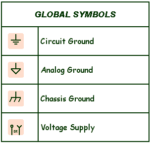
Other Symbols
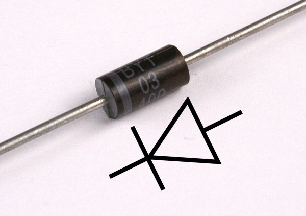
A diode is signified by an arrow head with a line. It allows current to flow only in one direction. It must always be installed in the right direction or a short will occur.
Lines in drawings indicate copper traces on the circuit board, or wires. In the drawing, when the lines cross and there is a large “dot” there an electrical connection. If the lines cross and there is not a “dot” there is not a connection between the two lines.
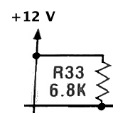
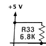
The pictures depict resistors connected to power. The left picture is connected to -12VDC.

The right picture is +5 VDC. Resistors are always a symbol of those zigzag lines and the letter “R”. The value for R33 is 6.8k ohms (6,800 ohms). R45 is 620 ohms.
The solid arrows indicate a connection to a power input to the circuit. It is important to note those as most logic probes will burn out if connected to more than 12 V (see your probe directions).
Ground is also indicated by an arrow, but the arrow is made of of lines rather than being a sold arrow. Most of the time, the ground symbol is the one on the top.
The IC

To the left is the numbering system for IC chips. Each IC has a dot or indentation to indicate the end. Note the position of Pin #1. Numbering then goes counter-clockwise.
ICs can serve a number of roles. Most used in pinball machines either act as buffers, amplifier, or decoders. A buffer or amplifier can be thought of as the same thing. A buffer acts exactly as it sounds; it provides some distance or protection. A buffer or amplifier can be treated the same.
 To the right is a diagram for a IC ULN2803. It is used in the Bally/Williams WPC switch column circuit on the CPU board. It looks complicated, but it is just 8 buffers (see ‘Buffers’ above). What comes in pin 1 will go out pin 18. In pin 2, out pin 17, etc. [Of note: that buffer symbol as a small “O” after the triangle. That just means that it inverts. If it goes in +, it comes out as 0. We don’t care!].
If troubleshooting this circuit, we would be looking for a similar signal in each pin that goes out the opposite pin (1 to 18, 2 to 17, etc.). If it goes in but does not come out, there is an excellent chance that IC is defective.
Decoder ICs – PIA

Decoder ICs take instructions from the CPU/MPU and send an output to each lamp or solenoid. In some machines, this chip is called a PIA.
The last part tested in the line is the decoder IC. Decoders can only work if all the inputs are connected. That includes the +5VDC, ground, plus all the data lines.
To the right is a decoder ship 4514 used in Bally pins. It takes 4 input signals and controls up to 15 different solenoids / lamps!
If you think you have a defective decoder chip, check the other outputs. If they are working, and there is missing only one output, that decoder is almost certainly defective. Note that defective resistors or diodes connected to the output can give the same indication as a bad decoder chip, so check those.
The data lines are marked D1, D2, etc. (or In A, In B…). Those data lines going to decoder are like words of instruction to this chip, telling which output to turn on. If one is missing, the chip will translate wrong. It might turn on random lamps, or none at all.
If the chip is not working at all, also check to insure that it is receiving voltage (VDD) , ground (VSS), strobe (ST) and inhibit (I) are getting signal.
The digital logic probe can perform all of these tests. Look for buzzing on the data lines strobe and inhibit. +5 should read high. Ground low. The outputs from the chip will change when that item is fired. If confused, compare the probe response on this chip vs. another identical chip. They must be the same pin by pin.
If one or more data line signals is missing on this chip, check the other chips. If those chips have signal, then there is a broken trace. If none of the chips have that signal, then it is likely to be a plug or pin issue going to this board or coming from the MPU, and all your lamps / solenoids will be going nuts or not running at all.
Understanding Digital
Digital is thought of as ‘1’ or ‘0’, ‘on’ or ‘off’, ‘one’ or ‘zero’. That works for what we are doing here. But in reality, the signal is rarely ‘zero’, and ‘1’ or ‘on’ is a value that can vary from circuit to circuit.
These digital chips will expect values between zero VDC and a slightly higher value as zero, then about 3 VDC and to 5 as ‘1’ or ‘on’. Values in the middle are noise and cause circuit malfunction. Noise is very difficult if not impossible to troubleshoot with a digital logic probe. Luckily, we do not run into noise issues too frequently.
TTL vs. CMOS
There are various switches on the Logic Probe. One is TTL and CMOS which are names of different types of IC chips. The setting on the probe depends on the chip under test. CMOS chips start with numbers 40XX or 45XX. TTL chips start with typically 74XX. Early ones were 93XX. Military grade are 54XX. Ignore letters like LS. You may have to shift this switch while moving from one chip to another.
TTL chips use 5 VDC only. CMOS chips can use much higher values.
TTL chips interpret a voltage of zero to 0.8 as zero / off. CMOS interpret a value of zero to 0.5 as zero / off.
TTK chips interpret a voltage of ~2 to 5 VDC as one / on. CMOS can interpret different values as one / on such as 3.5 to 5 VDC or even 7 to 10 VDC.
CMOS chips are generally less affected by noise.
More information about digital circuits.
Using The Probe
Hooking It Up
Always turn the pin off. Connect the black clip lead first to a central ground. Usually there is a TP (test point) ground at the power supply or driver board.
Determine whether your circuit uses +5 or +12 VDC and connect the red power lead to that supply (see specific instructions for what you are testing). That power supply is usually located on the driver board. If you are lucky, it will be a TP (test point). If not, pull out the schematic and locate an easy to find place to clip to. It could be the + side of an electrolytic capacitor.
These connections vary from game to game. Only after they are made, turn the game on. Turn the game off before removing the leads.
Note: Keep your probe away from voltages higher than 12V. When troubleshooting the solenoid driver board, touching the solenoid side of a transistor will destroy your probe. Sometimes, these transistors, such as a TIP102 or TIP122 will short the solenoid voltage to portions that should only have 5V. Always check those sections with your voltmeter first, to insure that your probe will not be destroyed.
Setting the Probe
Your probe likely has a TTL / CMOS switch. If your chip under test starts with a ’74’ or ’93’ (or even ’54’) it is a TTL chip. If it starts with ’40’ or ’45’ it is CMOS. For more information, see ‘TTL vs. CMOS’ above.
There is also a Norm/Pulse or Mem/Pulse switch. In most cases, set it to Pulse. However, when looking at solenoids or lamps turning on and off, set it to Normal. The setting may depend on your probe – consult your manual.
What to Look For
During test, look for a change on the probe’s indicators. It could go from low to high, high to low, or just pulse/buzz for a moment. If you see that, there is signal present at that test point. It does not matter to us if the signal is high, low or buzz. As long as it changes, it is (almost) certainly good. It is suggested that one check that the probe is setup correctly by testing a similar working circuit to see that the probe gives the desired results – low (green), to high (red), low to pulse, or high to pulse.
There can also be an intermediate level, not high enough to be fully on. On some probes, no light will go on. On others, both red and green go on. Since digital signals should be either on or off, the intermediate level is usually a sign of a problem.
Note: There are some occasions where the probe can buzz but the quality of the signal is not right. That is beyond the scope of this discussion.
Early Bally Troubleshooting
Bally Lamp Board ’76 – ’85
I had a Bally pin from the early 80’s with a lamp out. This system uses a lamp board that Bally (and Stern) used from ~1976 to ~1985 including Eight Ball, Eight Ball Deluxe, Silverball Mania, Mata Hari, Strikes & Spares, 6 Million Dollar Man, etc. It is a pretty basic system.
When a single lamp does not work on this pin, most will just slap in a new transistor / SCR. It usually fixes the problem, but not always. Pulling out your digital logic probe takes only a few seconds and will check your suspicion. Besides, it is a great way to practice.
Prior to proceeding, look at the drawing for a SCR above, and understand which lead is the anode, cathode and gate.

The image shows the circuit for the Bally lamps (click for larger image). The 5.4 VDC is applied to all the switched lamps, goes through the bulb then to the lamp board. A SCR (works like a transistor) shorts the circuit to ground and turns on the lamp. The SCR is controlled from the output of U2 (a decoder chip).
In this case, the bulb below the “I” insert on the playfield, does not work. Prior troubleshooting, you have already shorted the wire at the connector J1-1 to ground to see that the lamp comes on (or you should not be doing this!). That proves that the power is available to run the lamp, the bulb and socket are good and the wiring is working.
If the bulb is locked on, it is also worthwhile testing to insure that it is a shorted SCR prior to replacing.
Hooking up the Probe

See “Using the Probe“, above. Turn the power off to the pin. There is a convenient TP (test point) marked “GND” (ground) on the Driver Board. TP1 is +5V DC. Note that there is dangerous high voltage nearby that may run 200 volts or more.
Turn on and boot the pin. Press the button inside the coin door to enter the service menu. All controlled lamps will flash. Touch the probe to the top lead of Q29 (A), which is the Gate of the SCR. The probe should react with the flashing lights. If it does, the SCR is almost certainly defective. We can assume it is defective, because the SCR is receiving the signal to turn on, and it is not turning on.
Prior to replacing the SCR, it is a good idea to test continuity from the anode of the SCR to the plug pin coming into your transistor under test (in this example, J1-1). Also check to be certain that the cathode is grounded. This can be done with the probe. Touch it to the Anode of the SCR. It should be red (high). Test the other lead. It should read green (low). Note in this case it is safe to test the input from the lamp since it is in the safe operating range of the probe. But in solenoid / motor circuits, this check would destroy the probe.
If no pulsing at the gate of Q29 (A), move onto (B) R29. If pulsing there, then there is a broken trace / solder between R29 and Q29.

No pulse? Move onto the other side of R29 (C). If the probe pulses, then R29 is defective or there is a bad solder point.
No pulse? Move onto the IC (D) U2 pin 11. If there is a pulse there, suspect a broken trace or bad solder between there and R29? No pulse and this is the only light not operating? Suspect U2 as defective.
U2 is one of those ‘magic’ decoder chips. See the Decoder Chip section. Check other outputs at pins 4 – 11 and 13 – 20. Also check to insure that R29 is not shorted. A bad resistor can make it appear like the decoder chip is defective.
Note that it is easy to have the probe slip and hit two legs of the IC at the same time. Usually this is not going to cause a problem, but it is best to avoid this.
Bally Lamp Board Test Procedure
Bulb is not flashing during the lamp test. A “Yes” below means pulse on the probe; or a flip from high to low, or low to high. Click on ‘Bally Lamp Board showing test locations‘ photo above, for test points.
1) Test at (A). – Yes = replace SCR (Q) – No = move to (B)
2) Test at (B) – Yes = bad trace or solder R29 to Q29 – No = move to (C)
3) Test at (C) – Yes = bad R29 or solder – No = move to (D)
4) Test at (D) – Yes = bad trace or solder U2 to R29 – No = Bad U2 (see decoder ICs).
Bally Driver Board ’76 – ’85
Troubleshooting a failed solenoid is similar to the Bally lamp board. In the case of a failed right slingshot, the power comes in J5-15 and is controlled by Q10. Q10 is turned on and off by the output of U2 pin 13, via U3 pin 8 in and out through 7.
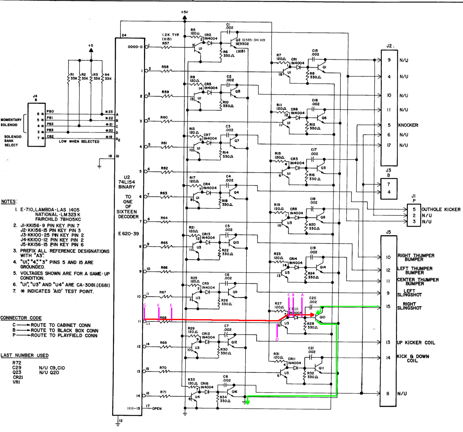
Prior to using the digital logic probe, it is assumed that you have done typical troubleshooting, which would include shorting J5-15 to ground (or the tab on Q10) to insure that the slingshot fires. This proves that the power supply and wiring is good.
Also, using your DVM, insure that ~43 VDC is not present at either side of the diode CR10. If it is on the banded side, then Q10 is shorted and must be replaced. Failure to check this could destroy your probe. If +43 VDC is on both sides, U3 is likely fried and the diode is bad.
After confirming that there is no high voltage present at diode CR10, we can safely hook up the digital probe (see “Using the Probe” above). Connect the probe to +5 VDC.
Turn on the power, enter the service menu and set the solenoids firing. The solenoids will fire in order. From the manual, the Right Slingshot is 04. When 04 fires on the menu, we should see a signal as drawn in the diagram (above).
Set the probe to point “A”. If there is a signal there but the solenoid does not fire, then Q10 is likely defective. Confirm with your DVM that there is a connection between Q10 and J5-15, Q10 and the diode, and Q10 and ground, prior to replacing Q10.
If no signal at “A”, test “B”, the non-banded side of diode CR10. If signal there, the diode is defective. This is unlikely, so check your work. If the diode is bad, are you sure that Q10 is not shorted? Also check R28. A bad R28 will act like a bad diode to the probe.
If no signal at “B”, check “C”, pin 7 of U3. If signal there, the trace / solder is bad between U3 and diode CR10.
If no signal at “C”, test “D”, pin 8 of U3. If signal is there, U3 is likely defective. Confirm that other solenoids using U3 work prior to replacing it. Also check R27. A bad R27 will give the same indication as a bad U3 to the probe.
If no signal at “D”, test “E”. If signal there, trace / solder is bad between R68 and U3-8.
If no signal at “E”, test “F”. If signal there, R68 is open, or more likely a bad solder joint.
Signal at “G”? Then a broken trace between U2 and R68. If no signal at “G”, U2 pin 13, then U2 is likely defective. U2 is a decoder chip – see the Decoder Chip section. If one of the connections to it (pins 12, 18 – 24) were bad, many of your solenoids would not work properly.
Bally Driver Board ’76 – ’85 Test Procedure
Solenoid is not firing. A “Yes” means pulse; or switch from high to low, or low to high. Confirm no high voltage at (A) before proceeding. See photo for test points.
1) Test (A) – Yes = Replace Q10 (check traces first) – No = Test (B)
2) Test (B) – Yes = CR10 defective (check solder) – No = Test (C)
3) Test (C) -Yes = bad trace / solder -No = test (D)
4) Test (D) – Yes = U3 bad (check R27) – No = Test (E)
5) Test (E) -Yes = Trace / solder bad R68 to U3 -No = Test (F)
6) Test (F) -Yes = R68 / solder bad -No = Test (G)
7) Test (G) – Yes = Bad solder/trace U2 to R68 – No = U2 defective. See decoder ICs
Gottlieb System 1
Here, a Gottlieb System 1 SS pin and the 10’s chime does not work. Standard troubleshooting steps are:
1) Insure that the coil has voltage going to and from it – both sides of the coil.
2) Check that there is voltage from the coil at the connector to the driver board.
3) Short the connector on the board to ground to see if it fires.
1), 2), & 3) are pretty basic stuff. If you have not already done this, we would suggest that you are not ready to use a digital logic probe?

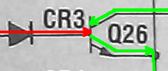
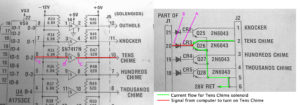
Here is a small section of a Gottlieb system 1 circuit for the chimes. It shows the current flow when the chimes are being fired.
Prior to getting out the digital probe, turn on the pin and hook up the DVM. Check the voltage at J2-2 and confirm that there is 28 VDC present.
Also, check both sides of CR3 (A & B on the photo). We want to be certain that 28 VDC is not present. If there is voltage there, then Q26 is blown (shorted) and must be replaced.
If there is voltage at the banded side of CR3, but not the other side, the diode is OK. If on both sides, the diode is also shorted. This is very bad news as it likely means the IC’s upstream are toasted too.
Note that Gottlieb did not include this protecting diode CR3 on some early boards. These were prone to blowing up components on the CPU board if the transistor shorted on the driver board, not a great design. Without this diode, a shorted Q26 will also take out the SN7417N IC.
If CR3 is not present, check J1-20 instead. If 28 VDC is there, Q26 is shorted and quite likely the SN7417N IC is fried.
See “Using the Probe“, above. Connect the probe to +5 VDC.
Enter the solenoid test menu and get the solenoid firing. On many early pinball machines, it is not possible to just fire one solenoid, so they will have to all be cycled. If possible, set it to fire the solenoid under test.
Note that it is possible to accidentally touch two leads at the same time. That can be a bad thing. It is also important to not touch the input side of Q26 with the probe. The voltage there is too high will destroy the probe. Do not use the probe on any part of the circuit with the ‘green’ line as the voltage will destroy the probe.
With the solenoid firing, touch the banded side (A) of diode CR3. The digital probe should flicker each time the solenoid/lamp/motor is supposed to fire. It must change state. Don’t be concerned what color LED is lit on the probe. As long as it changes, this part of the circuit is good, but Q26 is bad. Inspect for bad solder joints and cracks in the trace between Q26 and CR3. Otherwise, replace the transistor. If your board does not have CR3, use J1-20 instead, or identify the base of Q26 and test there.
No response on the probe? It looks like Q26 is good and the problem is upstream.
Next, move to the other side of that diode CR3 (B). Check for a pulse again. If it is there, but not the other side of CR3, then the diode CR3 is bad or there is a bad solder joint / broken trace. This is not likely to happen, so check your work. If CR3 is bad, suspect Q26 also.
If CR3 is not used on your board, check J1-20 or the base of Q26 instead.
Now move to the MPU board and check pin 6 if the SN7417N chip (C). If there is a pulse here, suspect the plug / interconnect between the two boards or the traces. Check the J5-10 and see if the pulse is there. If at this header pin, then it is the interconnect. If not, there is a crack in the board. Note that there are more than one SN7417N on this board so it will be necessary to figure out which one has pin 6 connected to J5-10.
Not at pin 6? Lets follow it upstream.
AND STOP HERE!
We would like to check pin 5 (D) and the output of U4 pin 6. But take a look at that voltage coming in. It is -12V. Remember that our probe is designed to measure zero and +5 VDC (or +12). Testing this is outside of what the probe is designed for. It MIGHT be possible to connect the black power lead from the probe to -12, the red power lead to ground, set the probe to CMOS and test. But if you try this and your probe destructs, you did not read it here.
U4 is a decoder chips – See the Decoder Chip section. If one of the connections to it (pins 10 -12, 15 – 19) were bad, many of your solenoids would not work properly. Unfortunately, these chips are no longer available. It maybe necessary to replace the entire circuit board.
There is another possibility: R35 and R47. R35 is there to give a little negative voltage to the input of SN7417N. R47 gives a slight positive voltage as default. If those resistors are shorted, open, or there is a broken trace / bad solder joint, then it will appear that the ICs are defective. But sure to check continuity with your DVM prior to ripping out and replacing the ICs.
While no diagnostic tool is certain, the logic probe can be a useful tool to figuring out what is wrong.
Gottlieb Driver Board Sys 1 Test Procedure
Solenoid is not firing. A “Yes” means pulse; or switch from high to low, or low to high. Confirm no high voltage at (A) before proceeding. See photo for test points.
1) Test (A) – Yes = Replace Q26 (check traces first) – No = Test (B)
2) Test (B) -Yes = CR3 bad or solder / trace – No = Test (C)
3) Test (C) – Yes = trace, solder or connector defective – No = Test (D)
4) Cannot test (D) or (E) because -12 VDC is applied and that is outside the range of the probe.
Williams System 11 Solenoids
Note: We have recently added an extensive discussion on troubleshooting Williams System 3-7, 9, 11 and Data East solenoids. But it is important to read this page first.
Standard troubleshooting steps are:
1) Insure that the coil has voltage going to and from it – both sides of the coil.
2) Check that there is voltage from the coil at the connector to the driver board.
3) Short the connector or tab on the TIP122 on the board to ground to see if it fires.
Note: If shorting the tab on the TIP fires the solenoid, but none of the solenoids work during game play, it could be a problem with the Blanking Circuit – see below.
Problem: A single solenoid does not work. Could replace the TIP, the driver transistor, the IC, etc., until it is fixed, but with a digital probe and a little bit of knowledge, you don’t have to. In this example, solenoid 15 does not operate.

1) Check the manual to see which transistor drives this solenoid. In this example, we are looking at Q14 and Q10 for sol 15. This is found on page 56a on F-14 Tomcat. For other games, look this page on the CPU board.
2) With the power on, connect a clip lead to ground. Ground braid should do. Touch the other one to the metal tab of the TIP transistor. The solenoid should fire. If it does not, there is a wiring / power / coil issue – fix that. If it does, there is a problem with the circuit.
3) Using a DVM, check for voltage between the TIP and the driver transistor (point A). If it is equal to the solenoid power (~ 50 VDC) you have a shorted TIP. Replace the TIP and driver transistor (see wiring diagram).
4) If only low voltage is present between Q14 and Q10, then it is safe to use a digital probe. Setup the digital probe as explained in “Using the Probe“. Connect the probe to Test Point 2 (ground) and the difficult to find Test Point 1 on the power supply board. TP1 is R13 left lead near the top of the board, immediately under 3J6. Set the probe to Normal & TTL. Enter the pinball troubleshooting menu and activate the solenoid (see operating manual for your game).
NEVER use the probe to test for the presence of the solenoid voltage (green lines) as that high voltage will destroy the probe.
5) During the solenoid test, the solenoid will turn on for a short burst, then off. When on, the probe should beep and/or become red/high. It will be low most of the time. Check for this pulse along the red line. Check the input of Q14 (A). If there is a pulse, replace Q14. If not, check the output of Q10 (B) to insure there is not a broken trace. Repeat along the red line.
6) If there is a pulse on the input of Q10 (C), but not the output, replace Q10. If there is a pulse on the input of U17 (E), but not the output (D), replace U17.
Note: A defective resistor in this circuit can also cause issues. Check to see if they are open or shorted. For example, if resistor SR4-8 is open, the pulse will never go high. If it is shorted, the pulse will never go low. If SR5-9 is open, it will never go low. If shorted, it will never go high.
7) If there is not a pulse to the input of U17, then we need to trace to the next chip. Reading this circuit diagram gets more complicated. This signal is coming in the “Solenoid Drives” signal. Note that the input to pin 9 is labeled as PB6.
If there is a pulse to the input of U17 (pin 9) , but no output from U17, it could be possible that the ‘Blanking Signal’ (see below) is not getting to pin 10. Note that pins 2, 13, 10, 4 are connected together. These all have to be high for the solenoid to operate. If, for example, 2, 13, 4 are high, but pin 10 is not, there must be a broken connection to this leg.

8) Looking on another page for the CPU, one will find a similar drawing labeled “Solenoid Drives”. Follow that to U10 and look for PB6. PB6 is pin 16. Check for high/low on pin 16 of U10. If present, check for a broken trace between the PIA and U17. If absent, it likely means this PIA is defective. Cycle through the other solenoids and check other pins on U10, pins 10 – 16. If a high/low is detected on other pins, but not the one pin, replace U10 – PIA.
Blanking in Williams System 11
Not yet addressed is the blanking used in Williams System 11 pinball machines. On power up, all the solenoids will lock on for a moment and, perhaps blow a fuse, until the computer boots. Williams solved this problem by creating a ‘blanking’ circuit to keep the solenoids from firing. If this system malfunctions, either all the solenoids will fire on start up; or none of the solenoids will work.
Usually, when the blanking circuit malfunctions, all the solenoids fire on start up. For system 11A, 11B and 11C, there are three LEDs (system 11 does not have these LEDs). The right one is the blanking circuit. It should be off momentarily on startup, then turn on and stay on.
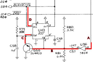
If the blanking system is defective, the cause is usually the U43 (555 timer chip). Also suspect would be Q50 (2N4403) or, less likely, C58 or U36 (pins 13 to 12). Using the digital probe, it would be possible to see the signal change at U36 pin 13, then 12), onto Q50, into to pin 6 of U43 and out pin 7 to the solenoids.
Checking these signals with the probe is not easy since they should switch in the first second at start up. However, there is a trick for some. If you are lucky enough to have a CPU with a ‘CPU Test Button’ on the left side, leave the coin door open and press this button. The CPU will repeat a memory test and reboot. Connect the probe as outlined in step 4 above. The following states will occur when blanking is on (right LED on the CPU is on): A=high, B=low, C=low and D=high.
If testing when the pin is fully booted without this switch, the signals are a bit more confusing: A & B are high/low pulse, C is a low / pulse, and D is high.
Williams / Bally WPC Troubleshooting
WPC circuit designs were used in both Williams and Bally pinball machines from 1989 until Williams stopped making pinball machines in 1999. This run of games was arguably the most successful and sought after pinball machines ever made.
The descriptions below assume a WPC-89 machines. WPC-S and WPC-95 are similar, but the plug and TP numbers might be different.
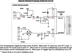
WPC Flashlamp / Solenoid Theory
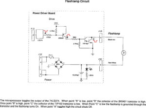
Both Flashlamps and Solenoids work in a similar fashion.
- Solenoids and flash lamps have power applied all the time.
- The solenoids and flash lamps are turned on at the driver board. A transistor (typically a TIP102) turns it on by shorting to ground.
- The TIP is controlled by a smaller pre-driver transistor.
- The pre-driver transistor is controlled by a IC.
- The IC receives instruction from the computer (via plug J113 – the ribbon cable).
Troubleshooting
Standard troubleshooting steps are:
1) Insure that the coil has voltage going to and from it – both sides of the coil.
2) Check that there is voltage from the coil at the connector to the driver board.
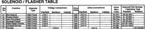
3) Short the connector or tab on the TIP102 on the board to ground to see if it fires. Look for the Solenoid / Flasher Table in the manual.
If shorting the tab on the TIP102 causes the solenoid / flash lamp to fire, then the problem is likely in this Driver Board.
4) Using your DVM set to VDC with the black lead grounded, check the voltage around the TIP102. While unlikely, it is possible that the TIP shorted through to the transistor. If that happens, testing this circuit with the digital probe will destroy the probe. The TIP and likely the transistor 2N5401 will have to be replaced. Also the IC may have fried.
5) After being certain that no high voltage is present, setup the digital probe as explained in “Using the Probe“. There are test points (TP) clearly marked as +5 and ground on the Driver Board. TP2 is +5 VDC. TP5 is ground. [Note that these test points are different on later WPC-95 pinball machines.]
6) Enter the service menu and the solenoid test (see the manual). Set the solenoid in question under repeat test fire.
Note that steps 7 – 10 can be reversed in order.
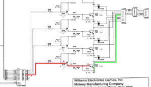
7) In this example, it is Q20 TIP102. Find the LS374 (U2 in this example) and test the leg with the probe at ‘A’. There should be a pulse every time the solenoid fires. If not, the LS374 might be defective. Other possibilities include the data lines D0 – D7, R22 and R23 (holding it high) or Q19 could be shorted to ground.
8) If OK, move onto ‘B’, the other side of resistor R22. If the pulse is not there, then R22 is open, the trace is broken, or R23 is defective.
9) Test ‘C’ at the output of Q19 2N5401. If missing, insure again that the pulse is on the input of Q19. If there and not at the output, Q19 is defective. Or, less likely, R25/R24 are bad, or the TIP base is shorted to ground.
10) If at ‘C’, check ‘D’. If not there, R25 or R24 are bad, or the trace is broken. If there is a pulse at ‘D’ and the solenoid does not fire, likely the TIP102 is defective.
Next: Troubleshooting the Switch Matrix and More advanced Digital Probe Diagnostics.
Comments
We are always looking for comments, including suggestions, improvements, errors, etc. for this page (see below). We are certain we have not thought of everything and there maybe mistakes.
If you have a specific question about your game that does not directly apply to this page, please see our FAQ section.
Additional Resources:
Wikipedia Logic Probe
Digital Logic Probe
How A Logic Probe Works
Logic Probe 101
How to Use a Logic Probe
Wikipedia Logic Gate
CMOS vs. TTL
Transistors as a Switch
Digital Logic Gates Symbols
Return to the Introduction to Pinball Repair and Maintenance
by
Copyright 2014 – 2024, all rights reserved.