Guide To Gottlieb EM Score Reels – Cleaning and Fixing
Prior to starting, please read the introduction and parts needed page.
Understanding the Switches
Note that the open / close state of these switches changes from generation to generation of the reel. The following description is for the 2nd and 3rd (last) generation of the Gottlieb Decagon reel.
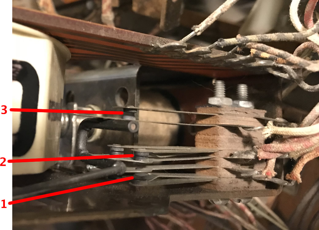
Each Gottlieb score reel has several switches, each one crucial to the operation of the pin. Failure of any switch in any reel can prevent the machine from entering game play.
- This tells the game that the reel is reset. If this does not work, the game will never start. The scoring reel in the cabinet will keep spinning. Also called the ‘zero switch‘.
- These switches make contact from 1 – 9. If these do not make contact, the score wheel will not move during the startup sequence. This is sometimes called the ‘runout’ switch.
- This switch makes contact on 9 and tells the pin to carryover the score to the next higher reel. This switch is usually absent on the highest score reel. Also called the ‘nine switch‘ or ‘On Add‘.

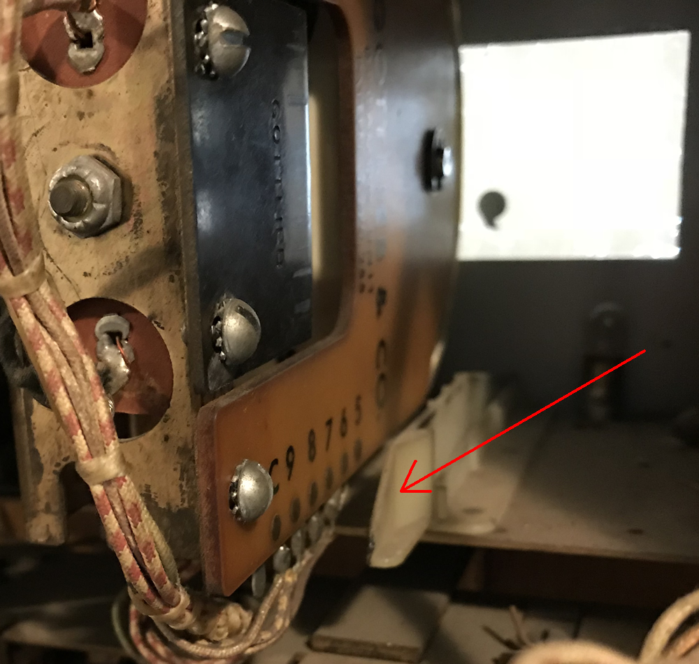
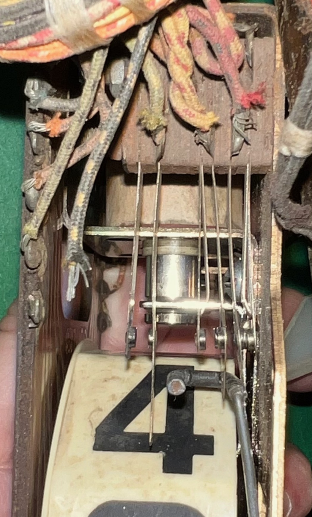
EOS Switch - This switch is a EOS (End of Stroke) switch. This makes sure that the solenoid is powered long enough to pull all the way in. When this switch opens, the power is removed from the solenoid and the number advances. If it opens too soon then there is not enough power. Not at all and the solenoid stays energized.
- This is a second ‘nine switch’ or ‘On Add’ switch. In conjunction with #3 switch, this switch is in series and the two are closed together momentarily when the reel advances from 9 – 0. This then advances the next higher reel.


For 1 – 3, each switch has two contacts. These are electrically connected together and are redundant. If either contact works, the pin will work. There are two contacts to increase reliability, so it is important that both be cleaned and make contact.
Switch sequence for 2nd and 3rd generation:
| Switch | Zero | 1 – 8 | 9 |
| 3 (top) | open | open | closed |
| 2 (middle) | open | closed | closed |
| 1 (bottom) | closed | open | open |
Switch sequence for 1st generation:
| Switch | Zero | 1 – 8 | 9 |
| 3 (top) | 0pen | closed | closed |
| 2 (middle) | open | open | closed |
| 1 (bottom) | open | closed | closed |
Step By Step Instructions For Making a Gottlieb Score Reel As Good As New
[For each image, click on it for a larger picture.]
Disassembly
 Hint: Place a cloth or similar into the opening from the backbox to the cabinet. This will catch any dropped parts before they disappear. And use a magnetic bowl to place the small parts.
The first time will be confusing and feel like it takes a long time. Trust me in that doing it a second time will be a lot quicker. After a while, you will be able to do this quickly and easily.
Note: For ease of reassembly and reference positions of parts, it may be helpful to have each score reel set to zero prior to disassemble.

 1) Remove the score reel from the cage located in the backbox / header. There is a tab holding the reel in place – push it to the side to remove the reel.
2) Remove the ‘C’ retaining ring and place it in your parts storage bin. If using muffin tins, number the holes (with a pencil!) and place this in the first hole. Move from hole to hole as you remove parts.
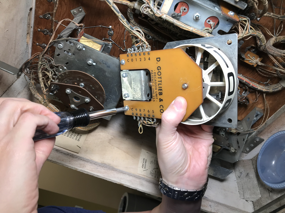
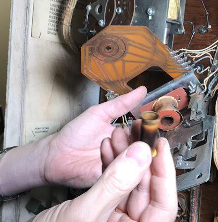
3) Loosen and remove the two screws holding the circuit board in position – while holding the other end in place. When these two screws and retaining ring are removed, all sorts of parts and springs can pop off and become airborne.

4) Carefully lift up the circuit board while holding onto the parts located on the numbered reel. There will be a metal electrical contact, a plastic piece, the reel and a spring all waiting to fly out into your room.
 This next step in important: Note the position of the metal contact. The single contact will be pointing to between the ‘5’ and ‘4’ on the reel. The backside points to between ‘0’ and ‘9’. When reassembling, it must be put back to that position [see photos].

5) Remove that plastic ring and metal contact and place it into your parts holder while holding the rest of the spring loaded parts in place. Underneath the metal contact is another plastic piece that must be carefully removed, while holding the number wheel in place.
6) Remove the numbered score reel and store it off to the side.
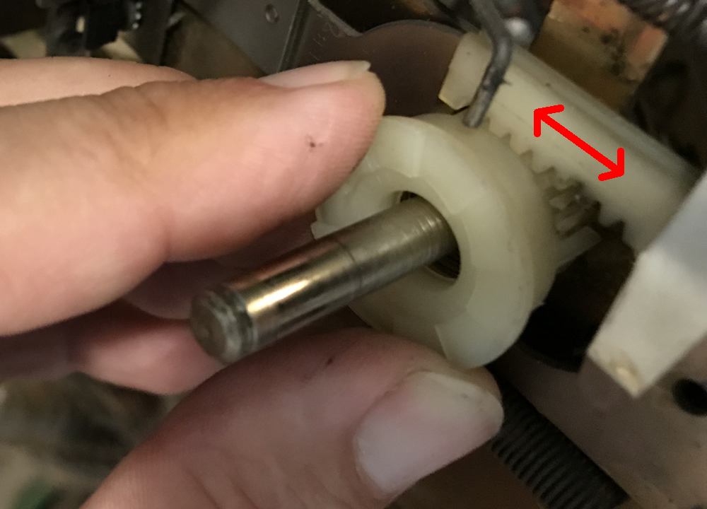
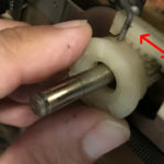
When removing the reel, this plastic part with gear teeth will be pushed out by the spring that is underneath. Prior to removing this, it is important to study its operation for reassembly.

7) Push the circular plastic part with gear teeth back down so that it engages the teeth of the slider part underneath. Now push the plunger into the solenoid and pull it back out. The left most gear tooth will fit into the left end of the slider [see photo]. The teeth on the wheel must line up so that they meet through the entire movement of the slider. If the circular plastic piece is positioned improperly, the teeth will ‘run out’ either when the plunger is pulled in or pushed out. Note how to align the teeth between these two plastic pieces for reassembly!
Now remove the plastic wheel and the spring underneath and place it aside.

8) Next we will be removing the parts attached to the plunger. First remove the bottom spring on the bottom of the slider mechanism. It is important to keep track of where each spring goes.
9) [This step is optional. Some people leave this in place.] Note the wire lever above and carefully note its position in the 3 leaf switch. These are switches 1, 2 & 3 noted at the beginning of this page. When reassembling, this wire must be positioned exactly between those leafs. Now, disconnect the spring holding onto the wire lever above. Remove the wire and spring and place aside.

10) We want to move the EOS switch, #4 and #5 (above) to get it out of the way. Some like to remove one screw and swing it up out of the way. I like to remove it completely – however, if all the screws are removed at once, the switch can literally fall apart.

Loosen both screws and then remove one. Swing it up all the way and then reinsert the screw and lightly tighten the nut. The do the same to the other screw and nut. Finally, tighten the screws and nuts down so they don’t fall off. Alternatively, the switch can be wrapped with a rubber band to keep it together.

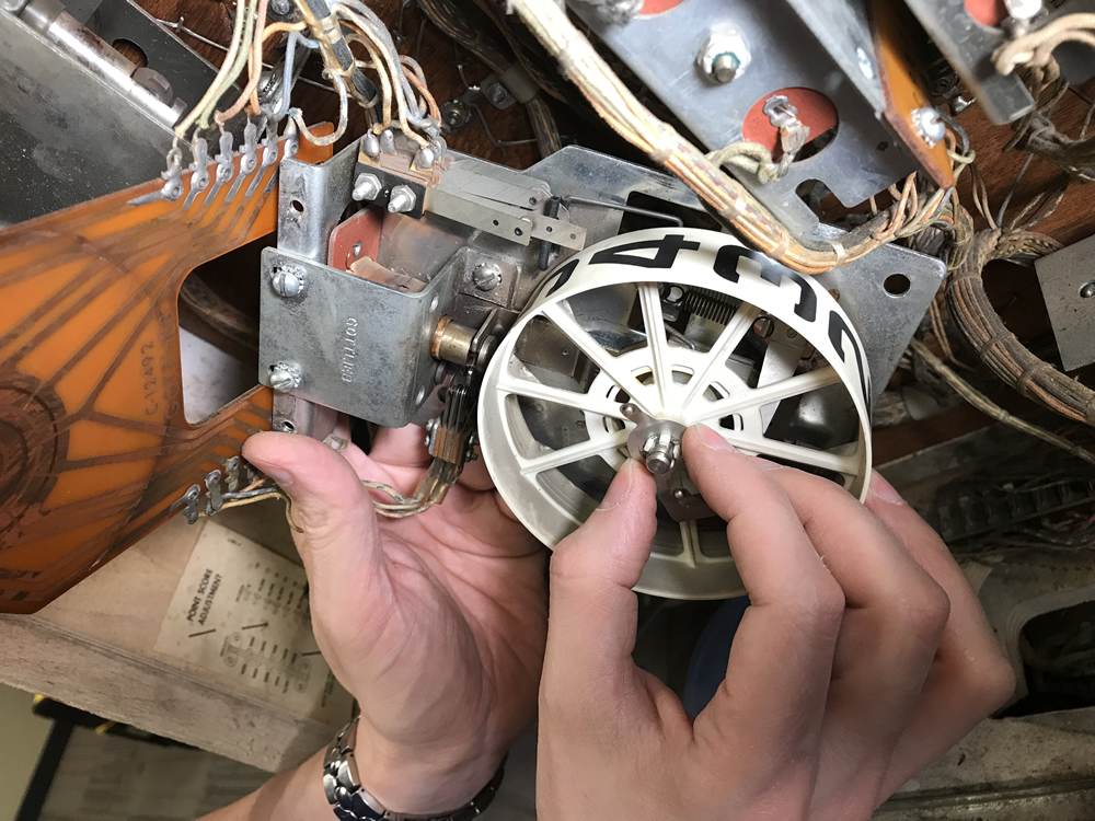
11) We are almost done with disassembly. Now remove the four screws holding the solenoid bracket in place. The remaining components will come loose.
If the coil sleeve is stuck in place, use a small screwdriver to free it. If not, it might break during this step.
12) The next set is awkward: Tilt the bracket and solenoid coil up and back while working the slider attached to the plunger. The bracket will have to be tilted about 45 degrees.

It is possible to remove all of this without having to unsolder the wires. Take note as to how you do this step because it will be doubly difficult to repeat it going back together.
Note that as the plunger comes free, there is a ‘U’ shaped guide where it connects to the slider. During reassembly, this guide has to oriented upright to receive the slider. It takes sharp eyes to see this guide.

13) Remove the slider and its spring to expose the base. Also remove the plunger from the coil and set aside.
You have finally completed disassembly and are ready for cleaning, then reassembly.
Cleaning
 14) Remove the coil sleeve. Either clean it with 91% isopropyl alcohol or replace it.

15) Also wipe around the coil for dirt as any remaining can gunk up an otherwise clean mechanism.
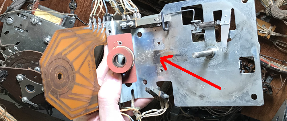
16) Take a look at the plate where the components move back and forth. This has to be smooth and clean in order for the reel to work smoothly.

Take a microfiber cloth and clean the surface with alcohol. Look for any groove or gouge marks. These need to be removed completely. Then bring out your Dremel and the 1/8″ carbon brush and/or sanding disk (see parts list) and shine this surface.
 17) When completed, the surface of the plate should be free of gouges and anything else that might cause the mechanism to drag across it. Clean that up with a microfiber cloth. Then, using small amounts of Mothers Mac & Aluminum Polish (see parts required), clean until no more blackened oxidation is removed. Then wipe clean with 91% isopropyl alcohol.
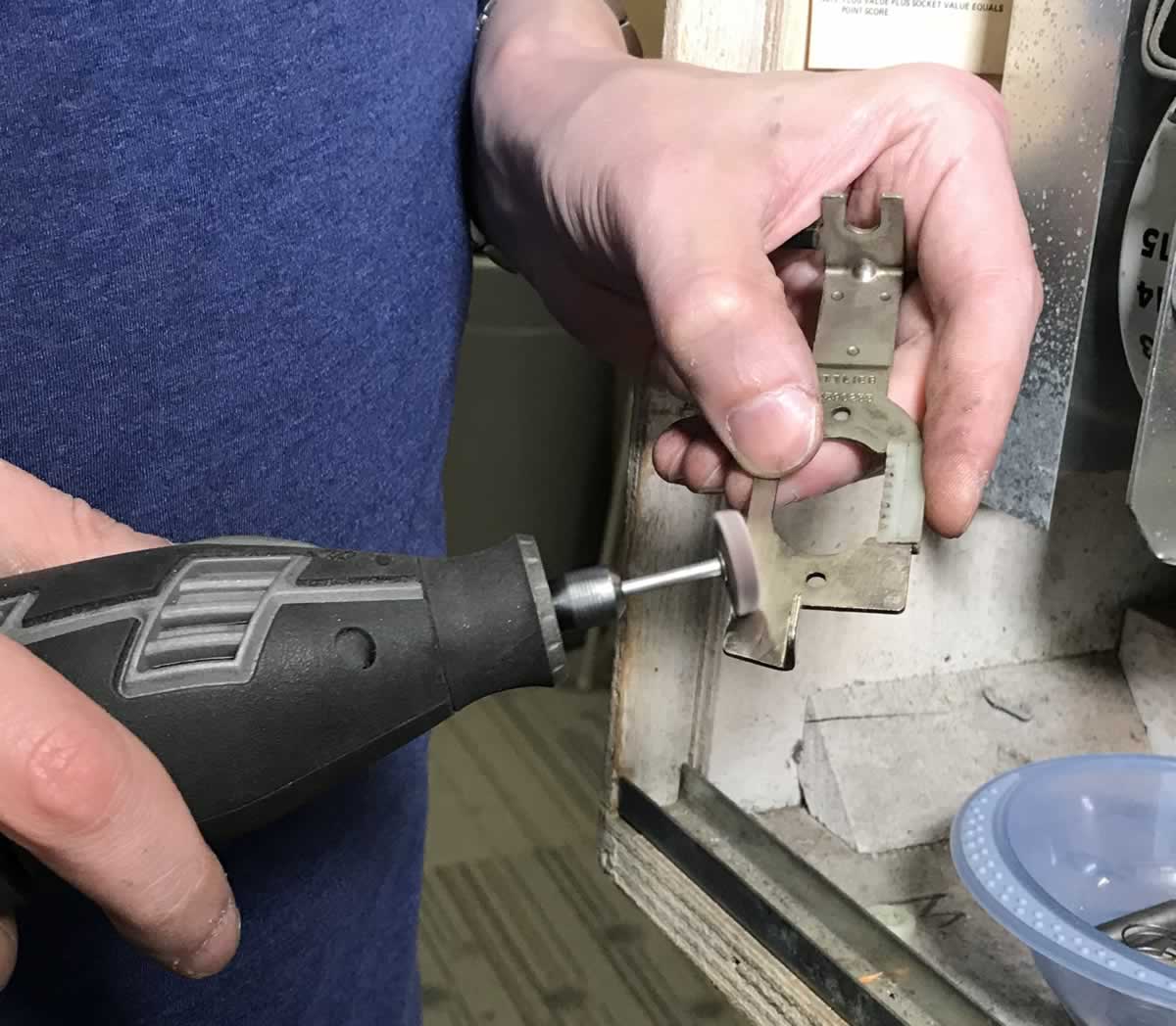
18) Use alcohol and clean off the edges of the slider mechanism. Take out the polishing or sanding wheel for the Dremel and shine up the edges of the slider mechanism that connects to the plunger. The edges of this get worn and this causes a drag as it moves back and forth – we want it nice and smooth. Use a q-tip to clean the plastic ‘gear’ teeth also.

19) Grab the bracket and buff that up also, in the area where the slider and bracket meet. This must be smoothed so that the slider will move freely.

20) When reassembled, the slider will move along two guides (see photo – one is hidden from view). Take the dremel carbon brush and clean any metal ‘burrs’ that might prevent the slider from moving freely. Clean with alcohol.
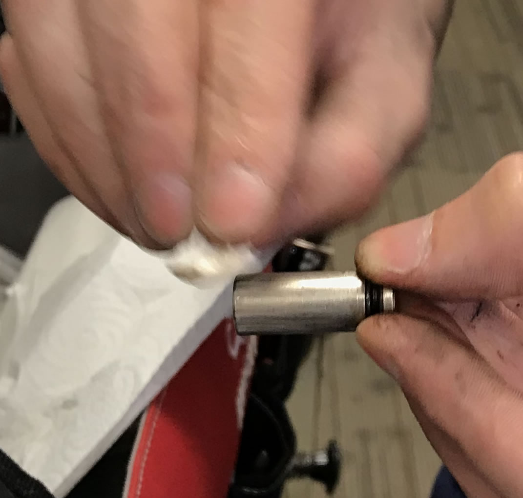
21) Grab the plunger and clean it up by wiping with isopropyl alcohol. If there are any rough edges, remove those off with the polishing wheel on the Dremel. The edges can be removed with a file, or a dremel sanding wheel, polishing wheel, or the 1/8″ carbon brush.
22) If the switch contacts are tungsten (gray metal and pitted), take back out the 1/8″ carbon brush and clean them. If the switch contacts are copper colored and not pitted, then clean them with a q-tip and 91% isopropyl alcohol. Be sure to clean the EOS switch also.
23) Grab the numbered scoring reel and clean it. It is possible to carefully clean the numbers with a gentle cloth and water with, perhaps, a small amount of detergent. But be careful as in a lot of cases, the numbers will rub right off.
But more important is to use a q-tip soaked in isopropyl and a cloth and clean every nook and cranny in that wheel. Any remaining dirt or goop will prevent prevent the wheel from locking into position.
Also clean and lubricate that rising and dropping ridge circling just out from the center. That is what the wire lever slides along.
 24) Use the Mothers Mac & Aluminum Polish and clean the circuit board until it shines. Clean until no more blackened oxidation is removed. Then wipe clean with 91% isopropyl alcohol. Use plenty of alcohol to remove all of the polish.
It is only necessary to shine up the area where the contact is being made.
Inspect where the wires are attached. Re-solder if necessary (add new solder to make it easier to melt). Be sure there is no extra solder making contact between the wires or across the board traces.
25) Clean the metal electrical contact that rotate around the circuit board. Depending on their condition, they can be cleaned with 91% isopropyl alcohol and/or the 1/8″ dremel carbon brush (gently!).
Lubrication
 Most pinball parts are designed to run ‘dry’ meaning no oil. But we now have ‘dry lubricants’ – meaning Teflon, so they can be used without the parts getting gummed up.
 26) Grab the Teflon lubricant and a Q-tip and lubricate the circuit board (lightly – 1 drop on the q-tip might be sufficient) and the metal area just shined on the bracket surface. Wipe off the excess on the circuit board with a microfiber cloth. If too heavy, the electrical conductivity might be poor.
Do not get any lubrication on the switch contacts.

27) Next, lubricate the sliding surface on the bracket polished up above in step ’17)’. Use the Finish Line Dry Teflon lubricant (or equivalent). Do not use oil of any type.
Reassembly
 The first step is the reverse of the awkward step during disassembly: reinsertion of the coil, coil sleeve, bracket, plunger and slider.
Just like this did not want to come apart easily, it tends not to want to go together easily. This takes practice and a bit of trial and error to get it all to come together.

 28) Grab the coil sleeve and insert it into the coil. The ‘collar’ side goes towards the coil stop. Then take the slider and hold it in position. You may find that now is a good time to install the spring on the slider to hold it into place. Place the coil bracket over the coil.
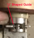
29) Grab the plunger and put it all together. Note that the ‘U’ – shaped guide has to be positioned with the open end up. Be sure to insert the plunger through the coil bracket. Be patient. This looks easy in photos, but it will take some contortions to get it all back together. In time, this will become a simple step.
Be careful not to force the parts together as this can warp the slider.

30) Screw the coil bracket into place.

31) If you removed the wire lever in step 9), reinstall it and its spring exactly like shown. If the wire is in-between the wrong switch contacts, the pin will not work properly.
32) Be sure to put back the EOS switch near the plunger back into position as shown in the photo. This was moved out of the way in step 10).

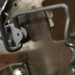
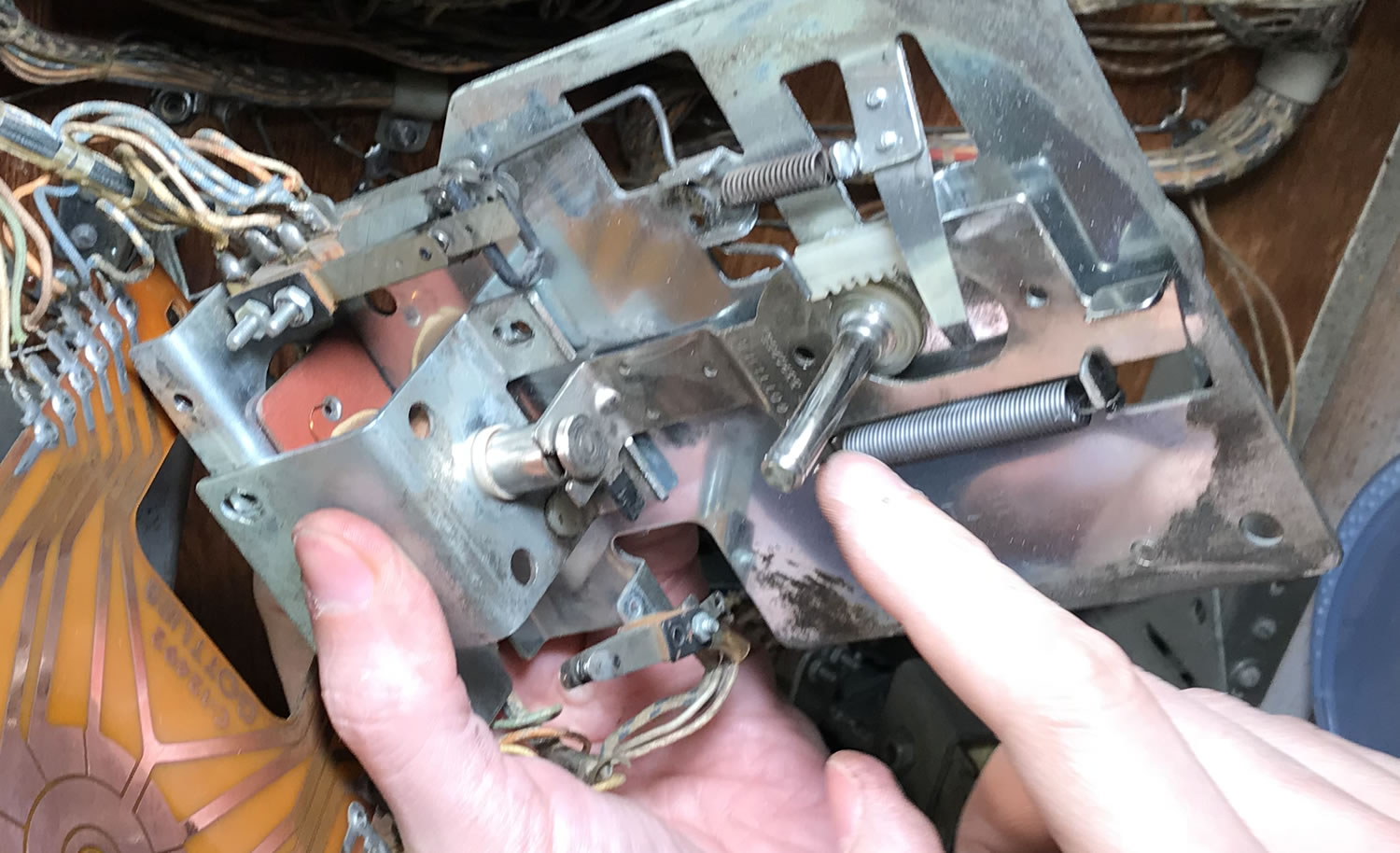
33) Inspect this part – the Reel Basket Backwards Latch. This is responsible for not allowing the score reel to turn backwards. The top part should be flat and not bent inwards. If necessary, use a switch adjustment tool to level it out.

34) Install the spring on the scoring reel shaft as shown.
Make certain that all the remaining parts are within reach for the following steps as you will have one hand holding the parts in the reel while the other is grabbing and installing parts.
 35) Refer to step 7) above and find that round plastic part with the gear teeth. Insert it over the spring from step 31) and press down until it engages the slider. Insure as you did prior to step 7) that as the solenoid pulls in, then returns out that the teeth of this part engage the slider throughout the entire run.

36) While holding the plastic part in proper place, insert the score wheel (numbered wheel) on the gear part installed in step 32). It is crucial to keep the gear from hoping out of its position. It does not matter what number is displayed on the score wheel. Hold the wheel in place to keep the spring from pushing it out.
37) Insert the metal contacts and final plastic part removed in step 5). Note that the wide end of the metal contact has to point to between zero and 9. If this part is not inserted properly, then various features on the game will not work properly. Be certain to hold all the parts in place and not let the spring push out. Note that some score reels will not have this contact.
38) If this score reel has a circuit board, swing it into place over the score reel while holding all parts in place.
39) Insert the retaining “C” ring over the circuit board to lock all the pieces into position. Insert the two screws holding the other end of the circuit board and tighten the screws.
Almost done. Now to check proper operation of the switches.
40) Refer to ‘Understanding the Switches’ at the beginning of this page. Insure that switches 1), 2), 3) open and close as the score wheel turns. Advance the score wheel by manually pulling in the plunger. While advancing the reel, insure that the Reel Basket Backwards Latch engages to prevent the reel from turning backwards. Inspect switches 4) and 5). Insure that the EOS switch stays closed and opens as the plunger pulls in fully.
All done. Insert back into the cage, power up and check for proper operation of the reel. Insure that as the reel moves from ‘9’ to ‘0’, that the next reel advances.
We suggest stopping with each reel completed, and test the system. If something went wrong, you will know which reel needs to be checked.
Troubleshooting
Everything is back together, the game is tested and it does not work? Here is a quick guide to troubleshooting.
Q1) The Score Motor keeps spinning after the reel sets to zero.
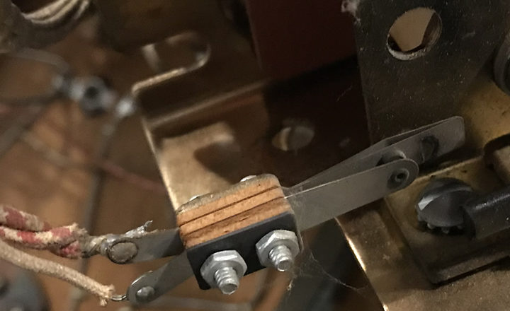
A1) Check the Decagon Switches. It is important that the switches all make contact as shown in the table at the beginning of this article. And the lever must be positioned properly.

The right side of the lever is below both leafs on switches 1 & 2.
Reposition the lever to be between those two leafs as shown in the second image.
Also insure that the wires are connected / soldered to the leafs. Use a voltmeter to measure resistance or ‘buzz out’ the contacts.
If this contact is not made for every reel at zero, then that score motor will not stop.
Q2) Reel solenoid locks on and does not turn off.
A2) EOS switch does not open when the solenoid pulls in.
Q3) “..the [score reel] relay keeps running….”
A3) Confirm that at the zero position, the Decagon Switches are properly adjusted. If switch 1 is supposed to be closed, insure that switches 2 and 3 are open. If all switches are supposed to be open, confirm that is the case. It is best to confirm this using a voltmeter as sometimes the switches appear to be properly set but are not.
Q4) I have put it all back together and the reel is binding up and not moving smoothly.
A5) Insure that the parts assembled in step 35) (see photo) are completely inside the slide. That includes the spring and the gear. These need to pass completely through the slide. Also insure that the slide can move the entire distance forward and back without hitting the end of the gear ‘teeth’.
It is then tricky to get the number reel in place without having all of this pop out and out of place. Check that has not occurred during reassembly.
Q5) It works fine, but cannot get to / past the 9 digit on the reel.
A5) Several different possibilities here:
– Did you completely disassemble the reel and clean plus lubricate everything?
– Does the reel spin smoothly (see Q4)?
– Did you clean the plunger, the coil stop and coil sleeve?
– The wire leaf slides against the back of the reel as the reel spins. Are all surfaces clean of gunk? A small amount of dry lubricant can be wiped with a q-tip along the travel in the back of the reel.
– And finally, when you adjusted the moving leafs on the Decagon Switches, did you adjust those leafs down against the wire lever too hard? They should be adjusted using the leaf switch adjusting tool so that the moving leaf just hits the lever, not pressing hard against it. And, it is possible to adjust the moving leaf for the 3rd switch so that it floats a little bit above the lever (see photo).
Comments
Comments, including suggestions, improvements, errors, etc. are welcome (see below).
If you have a specific question about your game that does not directly apply to this page, please see our FAQ section, where there is information on how to get help.
Note that we do not have access to Gottlieb® schematics. And, much of the time, we cannot answer specific questions – sorry.
I am in the process of restoring a Gottlieb PIONEER Pinball machine. After replacing one of the broken springs and cleaning the plastic parts, the score reel gets stuck on the “9th” position and won’t go to “0”? Replacing the Return Spring would help because the current ones look a bit rusty. Do you sell these springs?
We are sorry, but we are an information website, not a commercial one, and do not supply parts. Please visit our external links page and check out the parts suppliers. For EMs, likely the best supplier is Pinball Resource. Its owner, Steve Young, is a fabulous resource for all pinball machines, and especially EM’s. But other sites, such as Marco and PinballLife might have those springs, also.
In our experience, when the reel will not advance to zero, it can be a number of things, including:
1) The switch(es) that the reel has to move are too tight.
2) The main metal plate has worn groves on it which hang up the solenoid mechanism. This is the part that slides in and out of the coil. See step 16)
3) Spring(s) are weak.
Most people reflexively blame the spring(s) and sometimes tighten them. That is usually a mistake.
Be sure to disassemble and clean the mechanism, then adjust as outlined above.
https://homepinballrepair.com/index.php/external-links-the-most-complete-list-of-pinball-links/
After reading your question in greater detail, we would suggest that while new springs might help, it is likely that the reel is dirty. When you have a chance, please read through our procedure of cleaning the reel. The part of the article where we clean up, remove scratches, then lightly lubricate the bracket with Teflon grease is one of the keys to giving the reel the extra power it needs to push up on that switch and advance to zero. Also, careful adjustment of the switch, plus cleaning of the plunger and coil sleeve will also help.
Thanks for this post. I used it to fix a score reel on a 1970 gottlieb em. This is my first machine. I always knew there would be upkeep involved, but for a beginner it’s a bit intimidating. My issue was The tens reel was not switching over to the hundreds. It just continued adding up to 9 and then resetting back to 0. Using your information I was able to remove the score reel and clean the appropriate switch. The machine works great again. Thanks for the pictures and clear instruction.
Thank you for your nice note. It is much appreciated. If you see any areas that need improvement, please let us know.
Hello, I have a Royal Guard. My issue is sometimes when I hit a 10 point switch or 100 point switch the the correct reel turns plus the one next to it or sometime the 10 point and 1000 point reel will turn. I have cleaned and lubed all three reels and filled the contacts. When I put a businesses card in the 2nd switch place of all three switches the problem is greatly reduced. Any tips on how to solve this?
thanks
Hi Dan.
There are multiple possible issues that could cause this problem. Sometimes the relays switches are adjusted too close. Then, for example, the vibration of the 10 point score reel advancing can jostle the 100 point relay, causing the 100 point reel to advance.
Other times, it can be an mis-adjustment of the switch internal to the reel that is advancing. Royal Guard is a 1968 Gottlieb. On the Gottlieb reel page, there is a discussion of the switches.
https://homepinballrepair.com/index.php/em-score-reels-gottlieb/
If your reel looks like the first picture (2nd and 3rd generation Gottlieb Dragon), check the adjustment of the switches and the location of the lever. Switch #3 must be far enough apart that it will not inadvertently touch. If it does, then the next reel will advance. For example, if these two contacts touch in the 10 point reel, when the 10 point reel moves at all, it will also advance the 100 point reel.
Offhand, we are not certain which version of the Gottlieb reel your pin has. 1968 maybe first generation. Note the table further down the page. If you have a first generation Dragon reel, the proper open / close is different. That table will tell you what switches need to be open or closed, depending on the value on the reel. Insure that your switches move as required. If a switch is supposed to be open, but is so close that vibration could cause momentary closure, then this could set it off.
Please let us know if you have any luck in figuring this out.
Thanks for the tips but no luck yet. I am pretty sure I have 2nd/3rd gen but my EOS only has one switch.
I hit a 10 point switch, the M relay goes off and both 10, 100 reel turn. The L relay does not go off, so no vibration issue.
The problem usual starts when the sweep moves to the 1-8 position on the 10 reel and the 100 reel must be on 1-9 on the reel. In the 9 position, switch 3 closes, 0 it opens then on 1-8 it moves slightly closer. This causes the 100 reel to fire until it hits 0 then it takes a break as the 10 reel goes thru a full 1-9 rotation making the sweep close switch 3 and making it correctly fire then back to 100 firing along with 10.
I have experimented when the 100 is misfiring i put a business card in between the 3 switch contacts on the 10 reel. It will continue to fire both reels until 10 reel sweep moves to the 0 position then the problem will stop and the 100 reel will not incorrectly fire. How is the 100 reel firing when its not getting a signal from 10’s reel 3 switch due to blocked contacts?
Also sometimes when a 100 point switch is hit it will turn both the 100 and 10 reel or 100 and 1000 or all 3 will fire. Is it all connected?
What you are describing sounds like a classic case of a mis-adjusted switch.
There should be another switch on the reel. This stack of switches is usually visible looking through the reel itself. It is apart from the EOS switch which is located near the plunger.
This stack has a long metal lever going into it.
Your EOS switch is the second picture on this page. The switch stack is the first picture.
The only reel that might not have this stack would be a reel that is by itself (such as the free game reel). The highest number (say 100,000 reel) might not have that switch, since there is not another higher reel to activate.
I have a Gottlieb Batter Up. The score reel does not advance between the hundred and thousand reel. Thus if the hundred reel has a score of 800 and a five hundred point switch is hit the hundred reel will spin to 300 as it should but the thousand reel does not advance at all. Each individual reel will advance properly so a 1000 point shot will advance 1000, 5000 advances 5000, etc. I have checked the switches over and over and they are adjusted properly. There is current between the reels. Any suggestions?
From your description, it sounds like the 1000 point relay is working. So the issue has to be related to the switch in the hundred point reel or the wiring.
“I have checked the switches over and over and they are adjusted properly.”
I would check the resistance across that switch when it is closed. Use your voltmeter. Not sure which generation of reel you have, but it looks like it is the top switch.
Of course, one of the challenges of troubleshooting any Gottlieb pin via Internet is that the manuals are not freely available. The only Gottlieb EM we have on hand at the moment is a Play Ball. It looks like two things have to happen to advance the next reel: 1) that switch in the 100’s reel has to be closed, and 2) there is a switch in the scoring wheel on the bottom of the cabinet that has to close.
If you are at, for example, 800 and you score 500, I assume that the scoring motor turns. That 9th position switch has to be closed. And then a switch in one of the four positions on the scoring motor has to close.
You may want to go through, clean and adjust your switches in the scoring motor. We do not yet have a procedure for that on this website. Only for Williams (Bally is similar).
Great detail information!
Thank you for your nice comment. It is much appreciated.
-The HomePinballRepair team.
Great instruction on score reels. After cleaning all six score reels for this 2 player 1964 Gottlieb Sea Shore and also cleaning and adjusting when necessary the cabinet and head switches I have a small problem on the 2nd player 100 scoring
The one hundred score reel on 2nd player is not advancing. All of the score reels for both players reset to zero and are functioning otherwise.
If I manually engage the
Q 100 pt relay when 2nd player is up the 100 point Score reel advances like it should. It also advances sometimes in game play but mostly not.
All scoring is working on 1st player and I’m almost there on 2nd player except pesky 100 pts not working right. Hope to get this fixed so my kids can play each other.
It sounds like you have done some great troubleshooting. By finding that manually engaging the relay, the 2nd player reel 100 pt advances proves that this part of the circuit works.
So you need to troubleshoot why the relay is not activating when it should.
Usually, that is the switch in the 10 pt reel.
It is not clear to us which generation you have, but we suspect in 1964, it might be the first generation? That can be determined by looking at the switches and seeing the sequence of closing. If all three switches are closed at ‘9’ but open at ‘0’, then you have the first generation. But if the one switch (bottom) is open at ‘9’ and closes at ‘0’, then you have the second generation.
Either way, you need to insure that not only are the proper switches closed, but that they are making electrical contact.
We don’t happen to have an early Gottlieb circuit diagram on hand at the moment. But tracing through, finding those switches and seeing what needs to be closed to activate that relay will tell you what else needs to be checked.
We have also found situations where the switches were making contact, but the relay was not activating. In those cases, we have found a wiring problem (broken or strained at the solder joint), and sometimes a Jones plug issue.
Please let us know what you find.
This also points out the need for us to add to the information available on how to read and troubleshoot using a circuit diagram. We have a lot that we want to add to the website. The list is long.
Thanks for your guidance. It’s definitely 1st generation Gottlieb score reels. They are a bear to take apart and clean. The 1’s reel and 100’s reel each have a circuit board that has to be removed to get access to the switches. The 10’s reel doesn’t have this circuit board so access to the switches is way easier. The reel has a separate switch for the 9 position which is open and then closes when the reel is at 9. I cleaned this switch again and looks like it’s making solid contact. So with the 9 position switch closed the next playfield point should energize the 100 pt score Relay and in turn the 100 pt score Reel which isn’t happening. Instead the 10 reel just loops around to 0. If I want to jumper this to rule out the solder points do I put the alligator leads on each side of the 9 position sw on the 10 reel and connect the the other alligator leads to the lugs on the 100 pt score relay? I’m new to ems and haven’t done any testing with jumping.
So I dug a lot deeper on the schematic and think I’m making progress.
The 10’s score reel has it’s own separate 9 sw and there’s even a label that says “Top Cam completes circuit to “Q” 100 Pt Relay.
On each side of the 9 sw on the 10’s reel is GR-WH-RD and GR-BLK wires.
When I manually set the 10’s reel to the 9 position the 9 sw closes. I cleaned the contacts again.
Continuity on my meter is good from either the GR-WH-RD lug or GR-BLK lug to the Q 100 Pt score control relay which has a GR-WH-RD sw. When I check Ohms it’s 0.2. When the 9 sw closes it should fire the Q 100 Pt Relay.
I also checked continuity of the closed 9 sw from both the GR-WH-RD lug and the GR-BLK lug to the Jones Plug GR-WH-RD and also good.
Appears the circuit is good and closed.
I did the same test and compared on the Player 1 side that is working fine and got the same results and 0.2 ohms. Also good continuity to the Jones plug.
For this two player game there’s an O Relay labeled “1st and 2nd Player Scoring Control Relay” and a P Relay labeled “1st and 2nd Player Scoring Control Relay.” Not sure why it’s called “1st and 2nd player” since when player 1 is up the O Relay is engaged and when player 2 is up it’s always the P Relay engaging.
Like I said everything on Player 2 looks the same on Player 1 which is working fine so not sure why Player 1 isn’t working. I hope some of the above holds some clues and totally appreciate any guidance.
We wish we had the schematic so we could check. But there has to be another switch besides that in the 10’s score reel to activate the 100 pt relay. Otherwise, the 100 pt relay would activate when the 10 pt reel was sitting at ‘9’.
In a 1970 Gottlieb we are working on right now, that contact is in the 10 pt relay itself. So when the 10 pt relay is activated AND that position ‘9’ is closed in the 10 pt reel, the 100 relay is activated which advances the 100 pt reel, AND the 10 pt reel is advanced.
We have some experts who are not here at the moment and will hit them up for more info later.
When the score displays 90, for example, and I hit a 10 pt target the 10’s reel advances to zero but the 100’s reel doesn’t advance. So now the score is 00 instead of 100.
I emailed relevant snippets of the schematic.
Frustrated at first this has turned into a good problem finding your very helpful site. Thank you.
The two relevant parts are the 10 pt relay and the 100 pt relay. The 10 pt relay activates. Given that the score reel is at the 9 position, when that 10 pt relay activates, the 100 pt relay should also.
Looking on the left side under Relays, the 100 pt relay is ‘Q’ and located in 7D in the schematic. [Unfortunately, the numbers on the left side are cut off in your photo. That is OK, we can find it.]
There are a whole bunch of lines that can activate that Q coil. But the key ones are those that have ‘9th position ten’s unit’ in them. Those are the two lines near the bottom. One is for the 1st player reel and the other is for the 2nd player reel.
There are three switches that have to be closed for the coil to activate. 1) 9th position ten’s unit. 2) ‘O’, which is the first or second player relay (see Relays list). 3) ‘M’. Looking for ‘M’ on the relay’s list confirms that is the 10 point relay.
The nice thing about looking at the schematic, is we can see that there are two sets of switches 1) and 2). If one reel was advancing, but not the other, we would know that the problem is in either 1) or 2) switch. But our understanding is that it is affecting both reels. Neither player 1 nor 2 advances from ’90’ to ‘100’, right?
If so, then the problem must be on ‘M’ or the wiring to / from it.
So your next challenge, as we mentioned in our last post, is to look at the switches being activated on the 10’s relay. You are looking at the switch stack being moved by that relay. Specifically, this must be a switch that makes contact only when the relay is turned on (the contacts are pulled down) but not making contact when the relay is off.
We cover how to adjust these switches moved by the relay in adjusting scoring motors.
Check out https://homepinballrepair.com/em-score-motor-adjusting-repair-pinball/
and specifically look at ‘Understanding How the Switch Stacks Work’ & ‘Adjusting the Switches’.
With the information we have given here and on the site, we are confident that you can fix it.
Great info. Actually the 1st player score reels are working fine. It’s just the 2nd player 100 relay that is not being activated even when the 9 sw is closed on 10’s relay. With the 1st player reels working I’m fortunate for comparison and I will look at the switches more closely to compare them to the 2nd player and adjust them.
You mention the “O” player score control relay. When it’s the first player’s turn the O relay pulls in and when it’s 2nd player’s turn the P relay pulls in. I’m starting to think the culprit might be one of the Make/Break switches on the O relay. Will check that closely too (along with the P relay)
Score Reel fixed. Turns out it was a make/break sw on the O Relay (Player Score Control Relay.) And it turns out this was the first relay I readjusted after turning on the machine for the first time because it was buzzing loudly. The difference in making it work was the tightness of the relay screwed into the backbox bank of relays – finding the right balance of eleminating the buzz but not making it so tight to mess up the make/break. While frustrated in trying to fix this and play the machine as it should for two players, I got better at reading schematics, learned how to better adjust switches on relays, learned the mechanics and logic of rat trap score reels and associated relays, learned how to use jumper wires, and learned how to check connections with an ohm meter.
Excellent! We are glad to see that you are picking up new skills and knowledge. Whatever amount we helped, that is why we are doing this. Take care and have fun with pinball.
-The HomePinballRepair Team
Without your instruction on Gottlieb score reels and guidance, I’d still be spinning my reels, I mean wheels. Thanks for all your help!
I have an intermittent issue with my 1976 Solar City. About once every 30 or so games when I go to start a new game the reels reset but the score motor continues to turn, the ball in play light doesn’t come on and the ball is not kicked out. If you turn the machine off and back on again and start a new game it goes through the same reset sequence and works perfectly every time.
I have removed and cleaned score reels and checked the zero position switches and the intermittent issue continues.
I have not done anything to the boards inside the score reels and I can’t find what the purpose of the wiper arrangement on the boards are for…. I thought maybe it’s for number matching for free game credits but my machine is on free play so I have no use for that function. These do not also serve as a zero switch do they?
If it’s not the score reels then is it likely to be a switch on the score motor? If so which one is it likely to be? Turning the game off and back on results in the score motor turning 120deg and the fact the game always works after doing this (score reels are already on zero so don’t turn again, makes me think it’s more likely to be a score motor switch than a zero switch on the score reels)
Appreciate your thoughts.
Hi David.
Thanks for your comment.
We get so many specific questions about games that it is difficult for us to spend the time here to figure them out. We used to do that, but got overwhelmed. It is especially difficult with Gottlieb as the schematics are not freely available. We suggest going to either the Facebook pinball help groups or Pinside. Unfortunately, we have found that many of the people who try to answer there are well meaning people who do not have a clue. But there are people there who have lots of experience with EM pins and sometimes your specific game.
Intermittent problems are a pain to troubleshoot. Reproducibility is the key to figuring out problems.
As to your question about the boards and those wipers on the reels, they are usually used in the match, and extra ball functions. Some games have high score records, but not many EMs (our 1957 Williams Baseball does).
A score motor that does not stop is USUALLY caused by one of the reels not reaching zero, the zero switch not working, or the relay not disengaging. But there is also a switch on the score reel – 1C – that has to open up for that motor to stop. Usually that is not the issue since that switch opening is what causes it to stop. But if those contacts are nearly touching when that switch falls into the notch, it could keep on turning. But we say that is not normally the cause because if those leafs are too close, the motor would likely never stop turning.
So the odds of that one leaf not opening, vs. all those reels zero position switches favor the reels. But if the reels all reach zero and stop turning, but the score motor keeps turning, we would look closely at 1C.
The reel consists of two disks and posts that stick up and down. C is the upper disk and it usually has three indentations / notches. When it comes to a stop, there will be a switch on the #1 switch stack sitting in the notch on the top disk – C. That is what stops the wheel from turning (assuming all other functions have been completed), so take a look at that.
We wish you the best on this. Let us know what you find out. Thanks.
-The HomePinballRepair Team
Every 10 point switch also moves the 100 point relay on my Gottlieb Gen 1 score reels. Every time they move together. Moving the respective relays manually (M & L) does the same thing. All reel switches have been checked and reset correctly on startup. The 9th 10 point switch open and closes correctly. It’s as if the 10 point 9th switch causes the 100 point to increment every time.
Any idea what might be wrong? The description was great reading but I haven’t made any progress.
Thanks.
Hello Eddie.
Troubleshooting problems like this from a distance is a challenge for us, especially so since we do not happen to have access to that Gottlieb schematic. Our website is designed to enable people to do the research to figure problems out and we do not have the time to troubleshoot individual issues in detail – I wish we did and hope you understand.
In order for the 100 pt relay to be activated, there are several different switches that need to be closed and many of them operate in parallel. One, of course, is in the 10’s reel. We would put a piece of paper between the contacts of the 9th position switch. Since all three switches are closed in the 9th position, we would block them all and see if that stops the score of 10 pts from activating the 100 pt relay. There is also the possibility of a short where the wires come into the switch, so blocking the contacts is not a perfect test. A visual check is important there.
We are looking at a 1964 Gottlieb Sea Shore schematic – we don’t know how similar this is. On this one, ‘Q’ is the 100 pt relay. There are two leafs in the Q relay that are normally open. Those close when the 100’s relay is activated. It is crucial that these must be open when the relay is ‘off’. The other switches that, of course, need to open are the 9th position switch on the 10’s reel (is this a single player?).
There can also be other relays that can cause an issue. In this game, there is a ‘White and Purple Bumper Score Control Relay’ that turns on and off 100 pt scoring for those, and a similar one for Red / Yellow. Those could be not opening and stuck closed.
If you are not familiar with adjusting relay leaf switches, the section on the Score Motor in our website discusses adjusting leafs in a manner that is quite similar to adjusting relays. https://homepinballrepair.com/em-score-motor-adjusting-repair-pinball/
These are all shot in the dark type of troubleshooting since we do not have the schematic. Discussion groups such as: Google Groups Rec.Game.Pinball, Facebook and Pinside have active troubleshooting that might be of help.
Please let us know what you find out.
Thanks for your suggestions. I do have a schematic but it’s complicated with most all scoring going through these switches. It will take a wile but I’ll get it and let you know.
I decided to rebuild all 16 using your very good instructions. One score reel shutters, but works correctly. What causes this and how do I fix it?
It is hard to say for certain, based on your description. It could be a misadjusted EOS switch, or a bad plunger / coil stop. It is unlikely to be a bad coil. Or it could be a problem with the relay that controls the solenoid, or one of the switches in series with the relay that have to be closed for it to fire.
The problem was one blade of the 9th switch was touching the adjected blade of the runout switch, so at zero this caused my problem. No fish paper between these two blades. Furthermore, while I verified each switch operated correctly as I stepped through all ten positions, and even checked the metal, flat spring piece, I didn’t notice any contact between any two switches at all positions.
Great find! That tells us that we need to add a specific inspection of the fish paper between the switch blades. Thanks.
My 10’s score reel 0n my 1970 gottlieb was not triggering the 100’s reel, just kept resetting to zero during game play. After looking at the reel quickly and returning it to its spot, the machine won’t start properly. The motor just keeps spinning. Upon closer inspection, I now see the EOS switch (#4 above) is broken. Only half remains. The other side with its contact is missing. Perhaps this was a result of my earlier investigation. My question is if this missing switch would cause the game to not reset? Is this the cause of the spinning motor or should I check the 1,2, or 3 switch. Im wondering if this has always been broken and the cause of my initial problem or if it could be the cause of the new spinning motor issue. Secondly, I have access to switches from a 50’s era Bally back box. I was hoping to recreate the missing switch pieces with that? Does this seem like a reasonable solution?
The purpose of the EOS switch is to ‘turn off’ the solenoid. When the action is triggered, a relay is turned on to activate the solenoid. A switch in the relay is also activated to keep the relay on. The relay will stay on, until the EOS opens, the opening of the EOS switch breaks the circuit, which turns off the relay and the solenoid drops back.
Without that EOS switch, the relay will only be activated briefly, which is not enough time for the solenoid to pull in, therefore the reel will not advance. That is likely the reason that your 10’s score reel ‘was not triggering’.
I have a 1976 Gottlieb Surfer and the score motor just spins when you turn on the machine. I also noticed that the #4 switch on the player 1 “ones” score reel is missing one of the contacts. Will that missing contact prevent the machine from resetting? Another observation is that the “tens” reels on both player 1 and 2 does not have a circuit board. I assume this is normal only because I don’t see any loose wires that would have been connected there. A final note for now: your site is amazing. I am just starting to try to figure out my game and without your site I would not have a clue. Thank you very much.
Thank you for the nice comment. We very much appreciate it.
If we are understanding the question correctly, if the #4 switch is missing a contact (or leaf), then that reel may never advance RELIABLY. When the relay to activate that coil closes contact, the current flows through the coil and the relay is locked on until switch #4 opens. Switch #4 opens when the solenoid is pulled in completely which means the coil was energized long enough to advance the reel.
Without the #4 EOS switch the reel might be energized for a short time. That could be long enough to advance the reel (we are guessing). But the purpose of that switch #4, EOS switch, is to make certain that the activation is long enough and the movement of the reel is always reliable.
That could mean that the reel will never advance to zero. Does it? If you are finding that this reel works all of the time, that would be impressive. But for increased reliability, it is good to get it working. Steve Young of The Pinball Resource is generally the best place to get these parts.
If you have a reel that is not advancing to zero, you could try manually advancing that reel to zero to see of the score motor stops spinning. But if all reels are resetting and the score motor is still spinning, then either one of the ‘zero’ switches is not working, or the ‘home’ switch on the score motor is not.
This is for Bally and Williams, but the same principal applies – it is that the switches are designed differently.
https://homepinballrepair.com/em-score-motor-adjusting-repair-pinball/
That circuit board is part of the “match” function. The match should occur on only one of the reels of each player.
Sorry, I just saw your original reply. When I turn on my Surfer, the score motor spins endlessly. Neither player 1 nor 2 scores reset or attempt to reset.
The score motor will continue to spin unless the reels go to zero.
You can manually move the reels to zero. To do this, with the power off, push in on the plunger going into the solenoid for each reel. When at zero, check that all the proper switches are making contact. Start the game up. If the score motor stops spinning, then you know the cause.
If the score motor keeps spinning, then either one of the reels switches is not working, or there is another issue.
Regardless, you are going to have to fix the leaf on #4 (EOS) to get the reels to work reliably. And make sure the other switches are cleaned and adjusted to make reliable contact. This section on Score Reels will help explain how to accomplish this.
Your information is fabulous, I am especially grateful for your explanation of the scoring reel switch operations, but I am trying to reconcile some discrepancies with what I see. The hundreds reel on my 1970 Gottlieb 4Square oftentimes does not reset to zero. Without getting into a full rebuild, I hoped for a quick fix by adjusting the zero switch, but no such luck. The switches on the hundreds reel seem to allow much less tolerance for adjustment than on the tens reel. I would think they’d be identical. I am also puzzled by your explanation that says the double contacts provide redundancy, but my schematic shows one switch labeled “hundreds runout,” which energizes the “reset completed relay” and another switch labeled “hundreds unit runout” to energize the “Add hundreds unit.” The nomenclature confuses me, they seem to be calling these switches by the same name but there must be two of them. Any insight would be greatly appreciated. Thank you.
Thank you for your nice comments. We appreciate them.
There are some differences in generations of reels, but we have a lot of experience with 1970’s era score reels.
For others reading, a clarification: A ‘score reel’ is the module in the backbox that displays the game score. In most games, there are three or four of them for each player. There is also a ‘score motor’ and that is not what we are discussing here.
In most cases, the zero switch is normally closed. When the reel reset starts, a relay is closed. The relay stays energized because the relay now energizes itself. Part of that circuit that keeps the relay energized is the zero switch in the reel.
In looking at the Gottlieb Play Ball schematic, the relay K is the 1000 point relay. There are only two times it can be activated: 1) when the 100’s reel runs over from 9 to zero, and 2) when the 1000 point relay is turned on. When the 1000 point relay is turned on, a switch in that relay is closed and the relay will stay on until the normally closed switch in the reel opens. That is the zero switch which here, is strangely labelled as ‘on add “thousands” unit’.
https://homepinballrepair.com/wp-content/uploads/2023/01/Screen-Shot-2023-01-08-at-11.27.37-AM.png
The main differences between the reels is that, usually, the lowest digit reel has a small circuit board if the game has a match feature. The other reels have a roll-over to the next higher unit switch. But the highest digit reel is the simplest reel that has neither a match feature nor a roll over to a higher digit.
“The switches on the hundreds reel seem to allow much less tolerance for adjustment than on the tens reel.” We are not certain what you mean by this comment. The reel only has to open that switch for it to work. However, we have had some issues where the reel is not strong enough to move the switches when going from 9 to zero. In that case, we had to completely disassemble the reel and clean all contact areas to remove wear and dirt.
Let me first thank you for the pure delight I experience to see my 1970 Gottlieb 4Square reset to zeros when I start the game. That pleasure has eluded me ever since my good friend’s widow gifted me the game 2o years ago. Indeed, it is the pleasure of playing that has distracted me these months from responding to your last message.
When my hundreds reel would intermittently reset to 8, I expected the problem to be that the Zero switch was activated inappropriately but using a jumper to short a switch in a way that I can’t remember now, allowed me to realize the issue was actually with the runout switch not maintaining contact through the sequence completion.
My earlier comment about tolerance for adjustment on the score reel switches was just an observation that the switch leafs are closer together on the hundreds reel than on the tens, so it is more difficult to “hyperextend” the leaf to put a permanent bend into it.
I can’t thank you enough for the service you provide to our community.
Thank you for the very nice comment Dan.
A great catch on that runout switch. You have become an EM expert.
Hi
I have a 1974 Gottlieb hotshot four player and I am trying to sort out the scoring – according to you excellent instructions. But I can’t reconcile which score reels I have. I can’t set the leafs on the reel switches to operate as 2/3 generation because the third switch leafs don’t have a leaf that can be set as closed at zero position – and be opened at 1-9 – I did try setting them as first generation which is actually possible with the leafs – and looks like they should be like that – but then that just leaves the score motor churning away – how can I tell what reels I have?
We always worry that some ‘generally accepted information’ about generations of equipment might have exceptions. We hope that this is not one of them.
We manually advance the reel and watch the actions of the mechanism (or arms) against the switches. For example, in the photo titled “Gottlieb Decagon Switches”, watch how the ‘arms’ move against the switches. If it looks like the arm is pushing down or up against the switch, it should be apparent what the mechanism is trying to do – open or close a switch.
And note from the table, that all of the actions occur on zero, nine and one. When moving from eight to nine, look to see what moves. Watch what it is trying to do and make sure that happens by properly adjusting the switch leaf(s). Repeat as it moves from nine to zero. Then again from zero to one.
That should get things running for you.
Thanks for the reply – I have been watching the arm that follows the cam on the score wheel and trying to work out what it’s trying to do – that how I figured that the decagons in my machine couldn’t have a closed on zero position – I have a spare decagon that I got with the machine and that one definitely could be set as closed on zero as it has an extra leaf in contact with the cam operated lever which closes on zero – hey ho I will get to the bottom of it eventually I do have a full circuit diagram for the machine which if correct will let me sort it out – it’s just the cable colours are so faded they are impossible to distinguish – especially if you are colour blind !
Good morning,
I was having issues with my 100 score reel resetting with the new ball each time on my 1970 Gottlieb Baseball pinball machine. I made adjusted the switch on the 100 to make sure it was correct. After I put it together and cleaned the reels the 100 reel is buzzing and rattling, but will not move to rhe next number. It will get stuck on 3 and not move to 4. After I shut the machine off, it will then advance to the next number. Any idea what this might be? I checked for continuity and all the wiring is good. Relays have the correct resistance. I’m at a loss.
Thanks!
You have provided us with an important piece of information: “After I shut the machine off, it will then advance to the next number.” That means that it is likely not a physical problem where the mechanism is jammed.
Any time one hears a ‘buzzing’ on an EM pinball machine, the prime suspect is that a solenoid / relay is locked on. Sometimes, a relay is supposed to be on all the time. But in your case, that reel should only be buzzing when it is advancing, then turn off.
This sometimes results in a coil getting hot and burning. So far, it seems that you are lucky that it has not happened.
First thing we would check is that the EOS switch works in this reel. The EOS switch is outlined on this page on step 10). When that solenoid is activated, the plunger moves into the coil and then hits the EOS switch. It might be that is not happening.
We have a difficult time giving specific help on Gottlieb machines because the company has retained all the rights to their properties and they are not online. So all we can do is suggest going through the schematic and note what switches have to be closed for that solenoid on the score reel must be closed to activate the reel. Please let us know what happens. If you get stuck, we might be able to dig up a schematic to a similar game.
Hey guys. I am working on a Gottleib Vulcan. The 100 reel was locking on so I disassembled and cleaned it per your excellent tutorial. Then I had a problem with the run out switch staying closed when the zero switch was closed. I adjusted that and verified the switch contacts by manually actuating the reel. NOW when I fire up the game the 0-90 relay keeps running. I checked the schematics and it looks like this is activated by a closed runout switch (which are all open at zero). It also looks like this 0-90 works with the reset complete relay (AX) near the score motor. What would keep pulsing the 0-90 relay with all reels at zero and all run out swithces open and all zero switches closed?
I have checked the position of all the switches on each score reel for all players as well.
Dan R later got back to us and he had figured out the solution himself. Way to go Dan R!
“Thanks for the follow up. I did manage to isolate the issue. It was the runout switch and zero switch were making slight contact at the same time. Tricked the machine into thinking it was both at zero AND had numbers displayed.
Dan”
I have a Gottlieb Home Run 1971. The scoring is off. If the player hits a home run, they get four runs. If the player hits a double, they get four runs, etc.
I am scratching my head trying to figure out how the game figures this out.
Interesting as we had recently worked on a Gottlieb Playball. We think that the Home Run is an add-a-ball version of the same game. So we happen to have this schematic that we purchased from The Pinball Resource.
Looking at the schematic at 14E is the ‘add “ones” run unit’. In order for that coil to fire, either relay F and XB have to be closed, or the ‘”tens” unit runout’ switch and the ‘db2’ switch have to be closed. Motor 4A has four pulses per interval, so it sounds like that is firing.
We would take a look at ‘db2’ and see if it is closed. While this appears as NC (normally closed), it is part of the Control Bank reset unit. This massive bank is reset on power up. ‘db2’ should open at that time. We think you will find that this switch is misadjusted and is closed.